DC Voltmeter and Ammeter
•Download as PPTX, PDF•
0 likes•408 views

This document discusses different types of meters used to measure voltage and current in electrical circuits. It describes DC voltmeters, which measure direct current voltage using a calibrated scale. There are two main types: direct coupled cascaded amplifier DC voltmeters and chopper type DC voltmeters. Chopper type was designed to overcome issues like drift that the direct coupled type experienced. The document also discusses transformers, which are used to change voltage and current values in alternating current circuits but do not work for direct current. It provides the working principles and advantages/disadvantages of the different meter types.

Recommended
More Related Content
What's hot
What's hot (20)
Similar to DC Voltmeter and Ammeter
Similar to DC Voltmeter and Ammeter (20)
More from AL- AMIN
More from AL- AMIN (20)
Recently uploaded
Recently uploaded (20)
DC Voltmeter and Ammeter
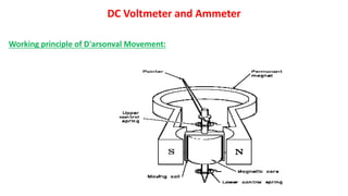
- 1. DC Voltmeter and Ammeter Working principle of D'arsonval Movement:
- 2. AC transformer : A transformer is an electrical device that uses electromagnetic induction to pass an alternating current (AC) signal from one electric circuit to another, often changing (or "transforming") the voltage and electric current. Transformers do not pass direct current (DC),so we can say it is a AC transformer.
- 3. There are various types of transformer used in the electrical power system for different purposes. They are- 1. Step up transformer 2. Step down Transformer 3. Power Transformer 4. Distribution Transformer 5. Instrument Transformer 6. Current Transformer 7. Potential Transformer 8. Single Phase Transformer 9. Three Phase Transformer 10. Current Transformer
- 4. Working Principle of AC transformer:
- 5. Fluxgate Magnetometer A fluxgate magnetometer is a device that measures the intensity and orientation of magnetic lines of flux.
- 6. Accuracy: The term ‘Accuracy’ is used to express how much is near the measured value to the true value. Basically, when we say the readings obtained are very accurate, it means the readings are true for all practical purposes. The accuracy of the two meters may be quite different. DC Voltmeter: The DC voltmeter is a device which measures the DC voltage applied to it, by moving the pointer against the perfectly calibrated scale. The calibrated scale is provided by PMMC meter.
- 7. There are two types of DC voltmeters: 1) Direct coupled cascaded amplifier DC voltmeter, 2) Chopper type DC voltmeter. Direct Coupled Cascaded Amplifier DC voltmeter: In this, the attenuator is comprised of various resistors of suitable value. The transistors used here are PNP and NPN, both the transistors are cascaded directly so that in the circuit the usage of more number of components can be minimized. Less the components used in the circuit less will be its complexity. The direct coupled cascaded amplifier DC voltmeter can be designed in two ways 1)Bipolar junction transistors(BJT). 2)Field effect transistor (FET).
- 8. Working principle: VCE =VCC – IC RC………….(1)
- 9. *Advantages: • It is a low-cost device. • It can provide the measurement of voltage in milli-volts range. • Its sensitivity is about 200kΩ/volt. *Disadvantages: • It is suitable to operate in a particular temperature range otherwise it creates drift problems. • There is a restriction in usage of multiple transistors for increasing gain as this will also result in drift problems.
- 10. Chopper Type DC Voltmeter: The chopper type DC voltmeter was designed to overcome the drawbacks of Direct coupled amplifier DC voltmeter. The drift problem was a big issue. This drift problem can be eliminated in chopper type DC voltmeter by using capacitor along with modulators. The DC voltage which is to be measured is obtained from low pass filter; this signal is then passed through a PMMC meter for the measurement.
- 11. *Advantages: • High sensitivity. • The measurement range is about 10µV. • It can measure voltage in micro-volt range. *Disadvantages: • The circuit of chopper voltmeter is quite complex. • increases the cost of DC voltmeter
- 12. Hall Effect: The hall effect is a consequence of charged carrier moving in the presence of perpendicular electric and magnetic fields . The charged carrier is deflected, inducing a hall voltage.The polarity of the hall voltage is a function of the semiconductor conductivity type.The majority carrier concentration and mobility can be determined from the Hall voltage.