Download as PPSX, PPTX

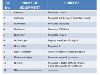
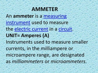
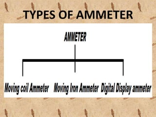
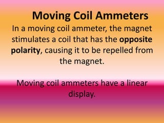
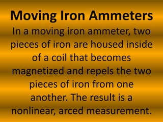
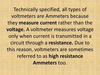
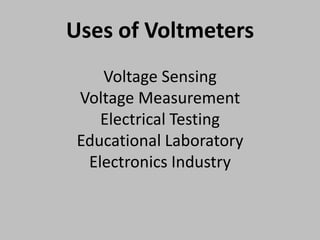
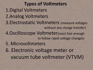
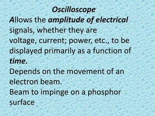
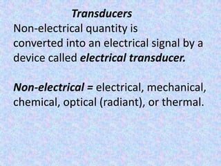
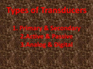
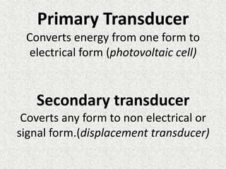
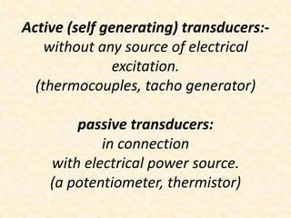
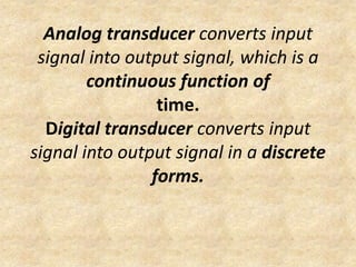
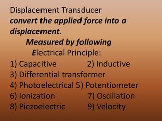
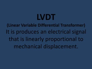
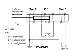


This document provides an introduction to electronic instruments and measurements. It begins with definitions of key terms like electronic, derived, and electron mechanism. It then lists and describes common electronic instruments like ammeters, voltmeters, wattmeters, multimeters, LCR meters, oscilloscopes, and signal generators. The document explains the working principles, types, and uses of ammeters and voltmeters in more detail. It also discusses transducers, displacement transducers, and LVDT transducers. In the end, it provides contact information for the author.

![Electrical measurement & measuring instruments [emmi (nee-302) -unit-4]](https://cdn.slidesharecdn.com/ss_thumbnails/electricalmeasurementmeasuringinstrumentsemmi-nee-302-unit-4-170607091611-thumbnail.jpg?width=640&height=640&fit=bounds)


![ELECTRICAL MEASUREMENT & MEASURING INSTRUMENTS [Emmi- (NEE-302) -unit-1]](https://cdn.slidesharecdn.com/ss_thumbnails/emmi-nee-302-unit-1-170607090405-thumbnail.jpg?width=640&height=640&fit=bounds)

![Electrical measurement & measuring instruments [emmi (nee-302) -unit-3]](https://cdn.slidesharecdn.com/ss_thumbnails/electricalmeasurementmeasuringinstrumentsemmi-nee-302-unit-3-170607091108-thumbnail.jpg?width=640&height=640&fit=bounds)


![Electrical measurement & measuring instruments [emmi (nee-302) -unit-2]](https://cdn.slidesharecdn.com/ss_thumbnails/electricalmeasurementmeasuringinstrumentsemmi-nee-302-unit-2-170607090943-thumbnail.jpg?width=640&height=640&fit=bounds)