Download as PDF, PPTX


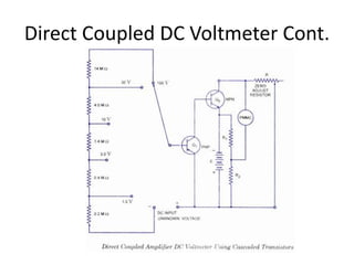
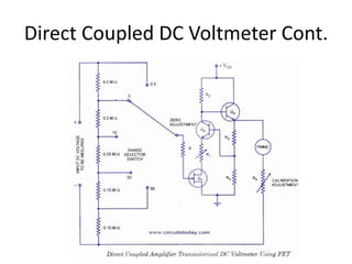
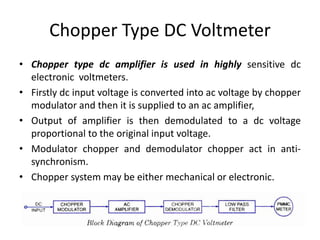
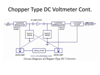
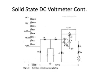
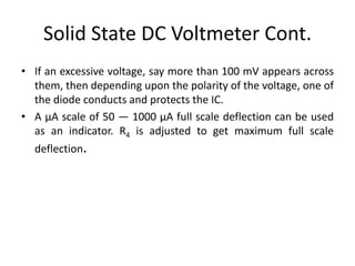


The document discusses different types of voltmeters including direct coupled DC voltmeters, chopper type DC voltmeters, solid state DC voltmeters, and AC voltmeters using rectifiers. Direct coupled DC voltmeters use cascaded transistors for amplification but have limited range due to gain. Chopper type voltmeters convert DC to AC using a modulator and demodulator to allow for higher sensitivity measurements down to microvolts. Solid state voltmeters use op-amps and feedback to adjust gain while diodes provide overvoltage protection. AC voltmeters use a bridge rectifier and meter movement to indicate the RMS value of an AC input signal.