Downloaded 531 times


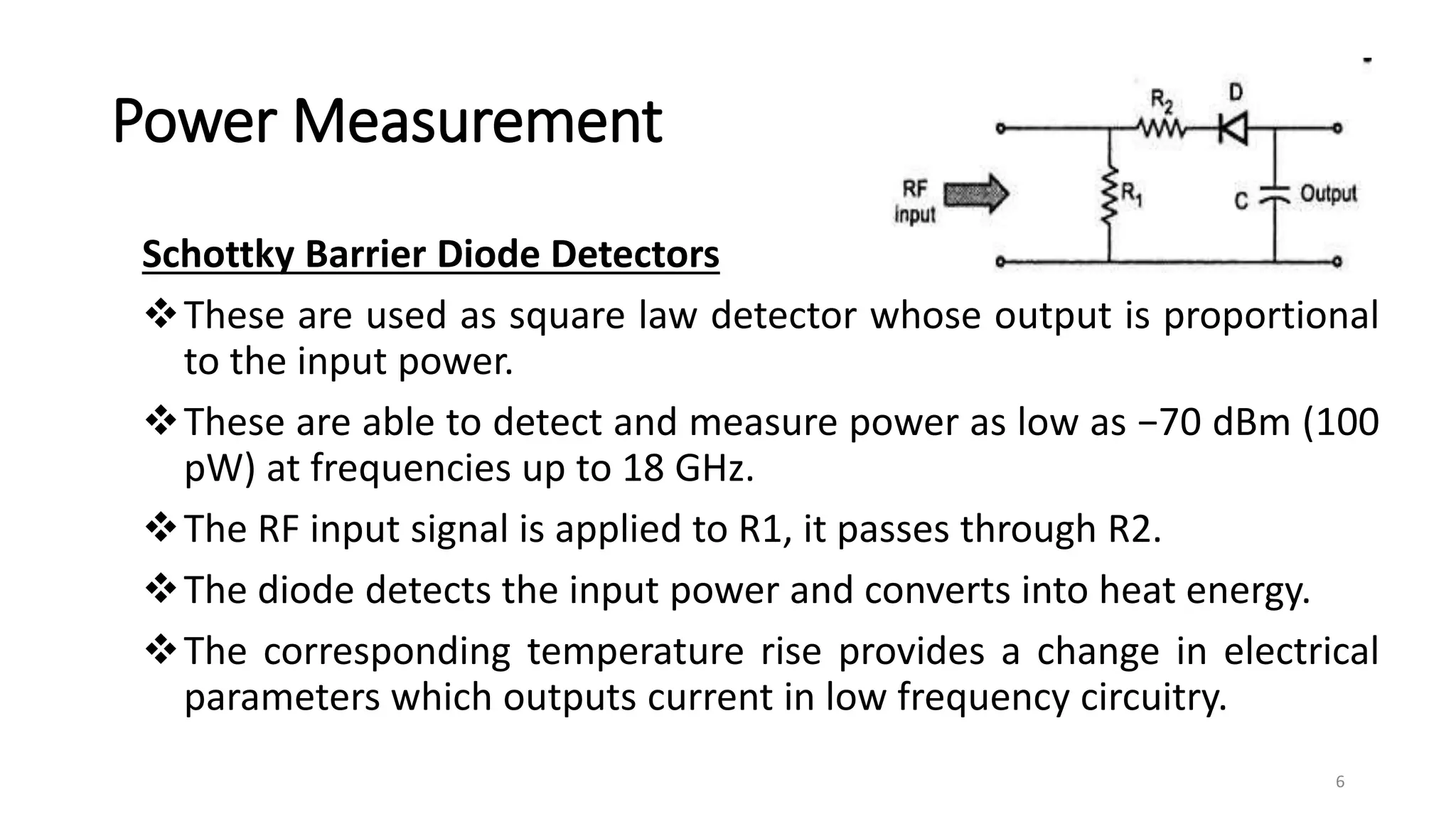
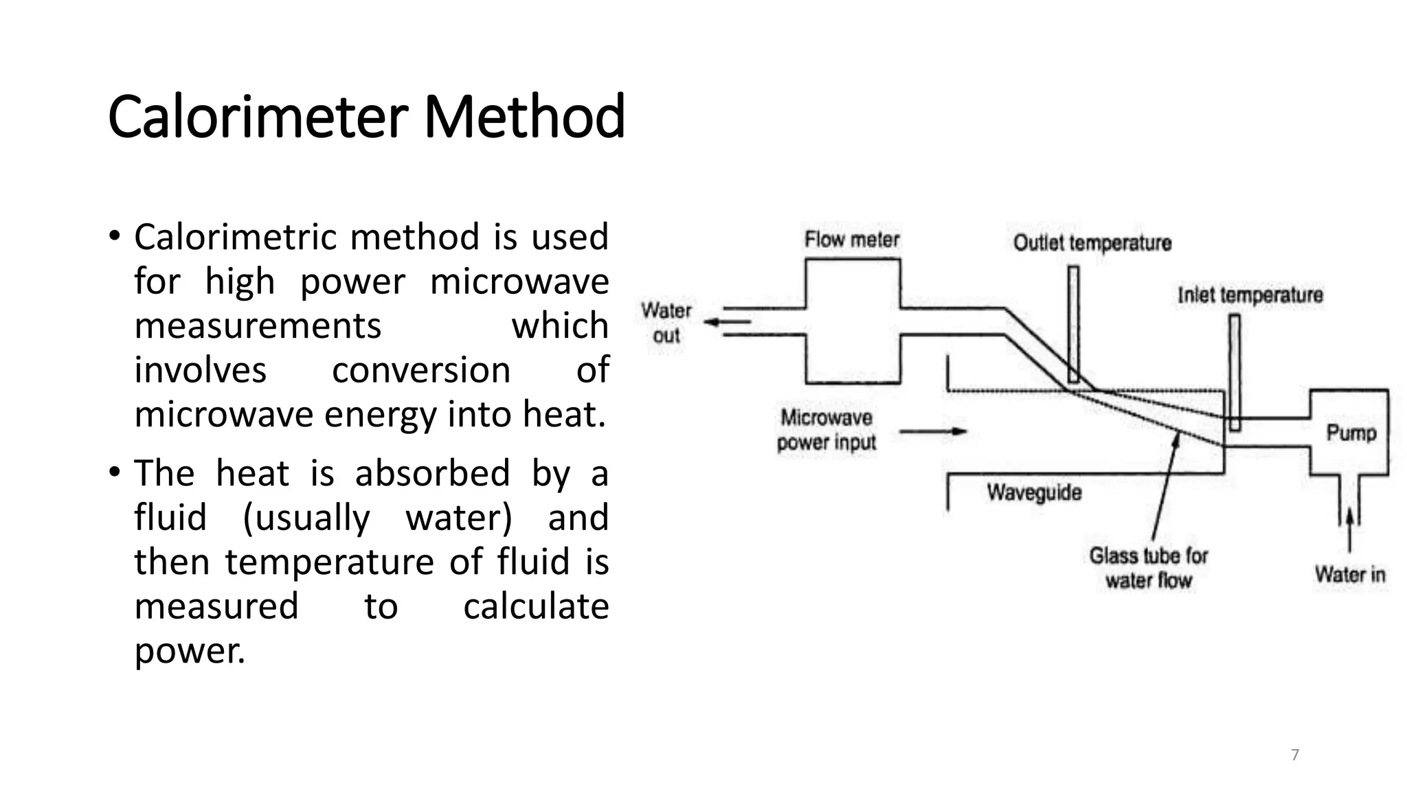


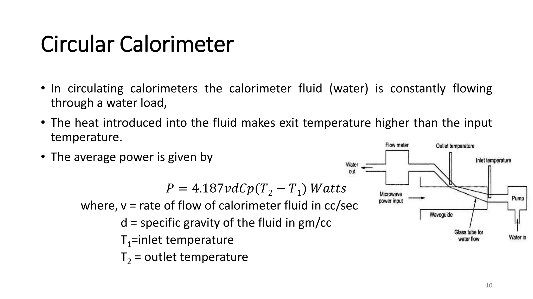


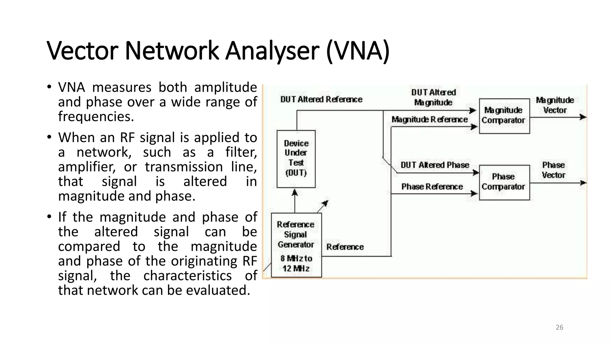


1. Power measurements at microwave frequencies involve measuring average power rather than voltage and current. Common measurement techniques include Schottky diode detectors for low power, calorimeters for medium to high power, and bolometer bridges. 2. Calorimeters work by converting microwave power to heat and measuring the temperature change of a fluid. Static and circular calorimeters are used along with calorimeter wattmeters to measure unknown power. 3. Vector network analyzers measure both the amplitude and phase of microwave signals, allowing characterization of devices under test.