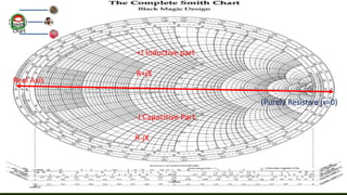
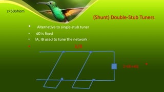
Date: Tuesday, February 25, 2020
Jatiya Kabi Kazi Nazrul Islam University ,Department of Electrical & Electronic Engineering
Presentation on Introduction to smith Chart
(1)AL-AMIN
ID:16102904
Session:2015-16
(2) SOMAYA SOLAYMAN MITU
ID:17102932
Session:20116-17
(3) Miskatun Zinan
ID:17102944
Session:2016-17
Studying at Jatiya Kabi Kazi Nazrul
Islam University Department of
Electrical & Electronic
Engineering
Smith
Chart
Index
 Introduction to smith Chart
 Normalized Impedance
 Constant Resistance Circles
 Constant Reactance ‘Arcs’
 Plot a Complex Impedance
 What about Admittance?
 Analysis of Single stub Tuner
 VSWR and Transmission Lines
 Analysis of Single stub tuner
 Analysis of Double-Stub Tuner
 Difference between single stub matching and double stub matching
 A 50 ohm transmission line is terminated to load of 25+50j. The length of the transmission line is 3.3 lemda.
Find:
(a)Reflection coefficient
(b)VSWR
(c)Input impedance
(d)Input admittance
Smith-
Chart
Smith-chart:
Introduction to
smith Chart
The smith chart , invented by Phillip H . Smith (1905-1987) is a
graphical calculator or monogram designed for electrical and
electronics engineers specializing in radio frequency
(RF)engineering to assist in solving problems with transmission line
and matching circuit .
A graphical tool to plot and compute:
 Complex impedance
 Complex reflection coefficient
 VSWR
 Transmission line effects
 Matching Networks
Normalized Impedance
• Normalized Z = Actual Z/System Zo
• For Zo = 50 ohm, divide values by 50
• Example,
• Z = 37 + j55
• Z’ = 37/50 + j55/50
• Z’ = 0.74+j1.10
• Makes it usable for any system Zo
Normaliz
ed
Impedan
ce
Real Axis
+J Inductive part
R+jX
-J Capacitive Part
R-jX
Smith-
Chart
(Purely Resistive jx=0)
Key Values on the Chart
Z0
system
impedance
Open
circuit
Short
circuit
Normaliz
ed
Impedan
ce
Constant Resistance Circles Constant Resistance Circles
Constant Reactance ‘Arcs’
Plot a Complex Impedance
• Z = 25+j40
• Divide by 50 to Normalize
• Z’ = 0.5+j0.8
• Find intersection of R’ = 0.5
• circle and X’ = 0.8 arc
Normaliz
ed
Impedan
ce
Adding Series Elements
• Add Components to move around the
smith chart
• Series L & C move
• along constant R circles
• Series L move CW
• Series C move CCW
Normaliz
ed
Impedan
ce
What about Admittance?
• Admittance is handy when adding elements in
parallel.
• Admittance Y = 1/Z
• Conductance G = 1/R
• Susceptance B = 1/X
• Converting Impedance to Admittance is easy with
smith chart
Normaliz
ed
Impedan
ce
Converting to Admittance
• Draw circle centered on Zo that crosses through Z
point.
• Bisect circle
• through Z and Zo
• Y is 180 degree
• away on circle ,
• Z’ = 1+j1.1,
• Y’=0.45-j0.5
Normaliz
ed
Impedan
ce
VSWR and Transmission Lines
• Constant VSWR circle
• Impedance varies
• VSWR stays same
• One trip around smith chart
• is ½ wavelength
• Impedance repeats
• Half way around is ¼ wavelength
• Open transformed to short
• Short transformed to open
• Transmission line effects
• Predict z vs line length
• Example
• Measure z at TX ,predict at antenna
Normaliz
ed
Impedan
ce
Analysis of Single stub tuner
Normaliz
ed
Impedan
ce
Single-Stub Matching: Steps (shunt version in parentheses)
• 1. Plot the normalized load impedance on the Smith Chart (and convert to admittance for shunt
stub tuning)
• 2. Draw the |Γ| circle and translate the impedance along the line to the rL=1 (gL=1) circle (2
solutions) => r’ = 1±jx’ (y’ = 1±jb’)
• 3. Determine load-section length d from angles between point representing zL (yL)and the point
on the rL=1 (gL=1) circle
• 4. Determine stub length ℓ between the open / short circuit point and the points representing ±jx’
(±jb’)
Normaliz
ed
Impedan
ce
• Z= 60+80j ohm
• Zo = 50 ohm
• Z’=1.2+1.6j ohm(divide by 50 ohm)
• D = 0.176 lemda – 0.436lemda= -
0.260+0.5lemda = 0.240 lemda
• jb1 = -j1.5
• Ls = 0.344lemda – 0.25lemda =0.094 lemda
Normaliz
ed
Impedan
ce
(Shunt) Double-Stub Tuners
• Alternative to single-stub tuner
• d0 is fixed
• lA, lB used to tune the network
• λ/8
•Z=60+40j
z=50ohom
• Line impedance Zo = 50 ohm
• Z = 60+40j ohm
• Z’ = 1.2+0.8j ohm
• Yl = 0.57-0.4j
• Moving on constant resistance value is
0.57+j0.06
• Jb1 = j(0.06 – (-0.4)) =
j0.46=l1=0.25lemda+0.068lemda=0.318lmda
• Move on original 1+jb circle value is 1+j0.57
• Jb2 = -j0.57=l2=0.416lmda-
0.25lmda=0.166lmda
Normaliz
ed
Impedan
ce
Analysis of Double-Stub Tuner
Normaliz
ed
Impedan
ce
Double Stub Tuner Steps
• 1. Draw the g=1 circle; this is where yB should be located.
• 2. Rotate this circle d0/λ wavelengths towards the load
(CCW); this is the circle on which yA should be located.
• 3. Plot yL on the Smith Chart.
• 4. Translate yL along a resistance/ conductance circle to get
onto the rotated g=1 circle
Normaliz
ed
Impedan
ce
• 5. Determine the stub length lA required to produce
the reactance/susceptance .
• 6. Rotate the modified load impedance/ admittance
onto the g=1 circle
• 7. Determine the stub length lB required to produce
the reactance/susceptance to move the rotated
impedance/admittance to the origin
Normaliz
ed
Impedan
ce
Single stub matching consist of the the short as well as open section
of a transmission line .This type of stub has the impedance just same
like those of the main line. Short circuited stubs are considered to be
more than the open because of its low energy radiation even at high
frequency.
Double stub matching is used as an alternative to single stub
because in single stub the stub is placed only at specific point and
that specific point may be at a wrong place where it is not needed
so the double stubs used to match the load .
Difference between single stub matching
and double stub matching
Summary
• The smith chart is highly useful tool:
• Complex impedance transformations
• Determining VSWR ,Rl and much more
• Transmission line impedance transformations
• Matching network design
Mathematical problem:
 A 50 ohm transmission line is terminated to load of
25+50j. The length of the transmission line is 3.3 lemda.
 Find:
I. Reflection coefficient
II. VSWR
III. Input impedance
IV. Input admittance
Normaliz
ed
Impedan
ce

Introduction to smith Chart

  • 1.
    Date: Tuesday, February25, 2020 Jatiya Kabi Kazi Nazrul Islam University ,Department of Electrical & Electronic Engineering Presentation on Introduction to smith Chart (1)AL-AMIN ID:16102904 Session:2015-16 (2) SOMAYA SOLAYMAN MITU ID:17102932 Session:20116-17 (3) Miskatun Zinan ID:17102944 Session:2016-17 Studying at Jatiya Kabi Kazi Nazrul Islam University Department of Electrical & Electronic Engineering Smith Chart
  • 2.
    Index  Introduction tosmith Chart  Normalized Impedance  Constant Resistance Circles  Constant Reactance ‘Arcs’  Plot a Complex Impedance  What about Admittance?  Analysis of Single stub Tuner  VSWR and Transmission Lines  Analysis of Single stub tuner  Analysis of Double-Stub Tuner  Difference between single stub matching and double stub matching  A 50 ohm transmission line is terminated to load of 25+50j. The length of the transmission line is 3.3 lemda. Find: (a)Reflection coefficient (b)VSWR (c)Input impedance (d)Input admittance Smith- Chart
  • 3.
    Smith-chart: Introduction to smith Chart Thesmith chart , invented by Phillip H . Smith (1905-1987) is a graphical calculator or monogram designed for electrical and electronics engineers specializing in radio frequency (RF)engineering to assist in solving problems with transmission line and matching circuit . A graphical tool to plot and compute:  Complex impedance  Complex reflection coefficient  VSWR  Transmission line effects  Matching Networks
  • 4.
    Normalized Impedance • NormalizedZ = Actual Z/System Zo • For Zo = 50 ohm, divide values by 50 • Example, • Z = 37 + j55 • Z’ = 37/50 + j55/50 • Z’ = 0.74+j1.10 • Makes it usable for any system Zo Normaliz ed Impedan ce
  • 5.
    Real Axis +J Inductivepart R+jX -J Capacitive Part R-jX Smith- Chart (Purely Resistive jx=0)
  • 6.
    Key Values onthe Chart Z0 system impedance Open circuit Short circuit Normaliz ed Impedan ce
  • 7.
    Constant Resistance CirclesConstant Resistance Circles
  • 8.
  • 9.
    Plot a ComplexImpedance • Z = 25+j40 • Divide by 50 to Normalize • Z’ = 0.5+j0.8 • Find intersection of R’ = 0.5 • circle and X’ = 0.8 arc Normaliz ed Impedan ce
  • 10.
    Adding Series Elements •Add Components to move around the smith chart • Series L & C move • along constant R circles • Series L move CW • Series C move CCW Normaliz ed Impedan ce
  • 11.
    What about Admittance? •Admittance is handy when adding elements in parallel. • Admittance Y = 1/Z • Conductance G = 1/R • Susceptance B = 1/X • Converting Impedance to Admittance is easy with smith chart Normaliz ed Impedan ce
  • 12.
    Converting to Admittance •Draw circle centered on Zo that crosses through Z point. • Bisect circle • through Z and Zo • Y is 180 degree • away on circle , • Z’ = 1+j1.1, • Y’=0.45-j0.5 Normaliz ed Impedan ce
  • 13.
    VSWR and TransmissionLines • Constant VSWR circle • Impedance varies • VSWR stays same • One trip around smith chart • is ½ wavelength • Impedance repeats • Half way around is ¼ wavelength • Open transformed to short • Short transformed to open • Transmission line effects • Predict z vs line length • Example • Measure z at TX ,predict at antenna Normaliz ed Impedan ce
  • 14.
    Analysis of Singlestub tuner Normaliz ed Impedan ce
  • 15.
    Single-Stub Matching: Steps(shunt version in parentheses) • 1. Plot the normalized load impedance on the Smith Chart (and convert to admittance for shunt stub tuning) • 2. Draw the |Γ| circle and translate the impedance along the line to the rL=1 (gL=1) circle (2 solutions) => r’ = 1±jx’ (y’ = 1±jb’) • 3. Determine load-section length d from angles between point representing zL (yL)and the point on the rL=1 (gL=1) circle • 4. Determine stub length ℓ between the open / short circuit point and the points representing ±jx’ (±jb’) Normaliz ed Impedan ce
  • 16.
    • Z= 60+80johm • Zo = 50 ohm • Z’=1.2+1.6j ohm(divide by 50 ohm) • D = 0.176 lemda – 0.436lemda= - 0.260+0.5lemda = 0.240 lemda • jb1 = -j1.5 • Ls = 0.344lemda – 0.25lemda =0.094 lemda Normaliz ed Impedan ce
  • 17.
    (Shunt) Double-Stub Tuners •Alternative to single-stub tuner • d0 is fixed • lA, lB used to tune the network • λ/8 •Z=60+40j z=50ohom
  • 18.
    • Line impedanceZo = 50 ohm • Z = 60+40j ohm • Z’ = 1.2+0.8j ohm • Yl = 0.57-0.4j • Moving on constant resistance value is 0.57+j0.06 • Jb1 = j(0.06 – (-0.4)) = j0.46=l1=0.25lemda+0.068lemda=0.318lmda • Move on original 1+jb circle value is 1+j0.57 • Jb2 = -j0.57=l2=0.416lmda- 0.25lmda=0.166lmda Normaliz ed Impedan ce
  • 19.
    Analysis of Double-StubTuner Normaliz ed Impedan ce
  • 20.
    Double Stub TunerSteps • 1. Draw the g=1 circle; this is where yB should be located. • 2. Rotate this circle d0/λ wavelengths towards the load (CCW); this is the circle on which yA should be located. • 3. Plot yL on the Smith Chart. • 4. Translate yL along a resistance/ conductance circle to get onto the rotated g=1 circle Normaliz ed Impedan ce
  • 21.
    • 5. Determinethe stub length lA required to produce the reactance/susceptance . • 6. Rotate the modified load impedance/ admittance onto the g=1 circle • 7. Determine the stub length lB required to produce the reactance/susceptance to move the rotated impedance/admittance to the origin Normaliz ed Impedan ce
  • 22.
    Single stub matchingconsist of the the short as well as open section of a transmission line .This type of stub has the impedance just same like those of the main line. Short circuited stubs are considered to be more than the open because of its low energy radiation even at high frequency. Double stub matching is used as an alternative to single stub because in single stub the stub is placed only at specific point and that specific point may be at a wrong place where it is not needed so the double stubs used to match the load . Difference between single stub matching and double stub matching
  • 23.
    Summary • The smithchart is highly useful tool: • Complex impedance transformations • Determining VSWR ,Rl and much more • Transmission line impedance transformations • Matching network design
  • 24.
    Mathematical problem:  A50 ohm transmission line is terminated to load of 25+50j. The length of the transmission line is 3.3 lemda.  Find: I. Reflection coefficient II. VSWR III. Input impedance IV. Input admittance
  • 25.