![COMPUTER AIDED DESIGN AND MANUFACTURING
Course Code 18ME72 CIE Marks 40
Teaching Hours / Week (L:T:P) 3:0:0 SEE Marks 60
Credits 03 Exam Hours 03
[AS PER CHOICE BASED CREDIT SYSTEM (CBCS) SCHEME]
SEMESTER – VII
Dr. Mohammed Imran
B. E. IN MECHANICAL ENGINEERING](https://image.slidesharecdn.com/cadcam-1module-2-211024034928/85/CAD-CAM-1-Module-2-18ME72-Part-A-1-320.jpg)
![COMPUTER AIDED DESIGN AND MANUFACTURING
Course Code 18ME72 CIE Marks 40
Teaching Hours / Week (L:T:P) 3:0:0 SEE Marks 60
Credits 03 Exam Hours 03
[AS PER CHOICE BASED CREDIT SYSTEM (CBCS) SCHEME]
SEMESTER – VII
Dr. Mohammed Imran
B. E. IN MECHANICAL ENGINEERING](https://image.slidesharecdn.com/cadcam-1module-2-211024034928/75/CAD-CAM-1-Module-2-18ME72-Part-A-1-2048.jpg)
![COMPUTER AIDED DESIGN AND MANUFACTURING
Course Code 18ME72 CIE Marks 40
Teaching Hours / Week (L:T:P) 3:0:0 SEE Marks 60
Credits 03 Exam Hours 03
[AS PER CHOICE BASED CREDIT SYSTEM (CBCS) SCHEME]
SEMESTER – VII
Dr. Mohammed Imran
B. E. IN MECHANICAL ENGINEERING](https://image.slidesharecdn.com/cadcam-1module-2-211024034928/85/CAD-CAM-1-Module-2-18ME72-Part-A-2-320.jpg)
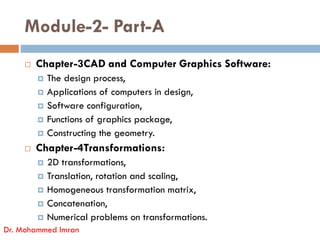
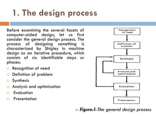
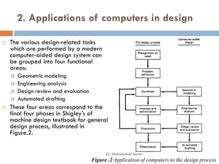
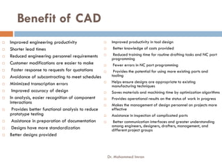
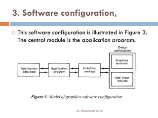
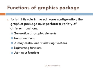
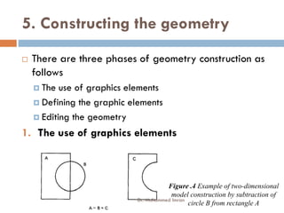

This document outlines the course objectives, outcomes, modules, and content for a Computer Aided Design and Manufacturing course. The key points are: - The course aims to teach students about concepts of computer-integrated manufacturing systems including CAD, CAM, automation, and modern trends like additive manufacturing and Industry 4.0. - The content covers topics like CAD software, geometric modeling, computer-aided process planning, CNC machine tools, and numerical problems involving geometric transformations. - The course objectives are for students to understand CAD/CAM applications, automated manufacturing systems, computer applications in design and manufacturing, and modern manufacturing trends leading to smart factories.