Download as PDF, PPTX

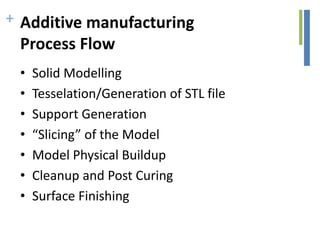
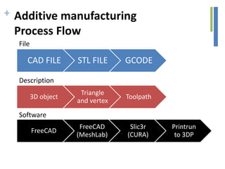
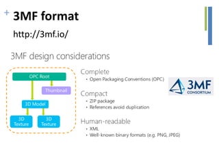
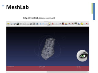

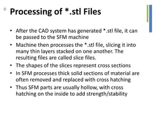


The document outlines the software and processes involved in additive manufacturing, detailing the steps from CAD file generation to the final 3D object creation. It explains the slicing of STL files, the use of support materials, and the basics of G-code programming for CNC machines. Additionally, it includes information on various software tools such as FreeCAD, Slic3r, and MeshLab used in the additive manufacturing workflow.


![Fairy Tailors - Case Studies [EN / US]](https://cdn.slidesharecdn.com/ss_thumbnails/fairytailorscase-studiesen-150418120438-conversion-gate01-thumbnail.jpg?width=640&height=640&fit=bounds)