Download as PDF, PPTX

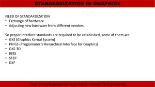
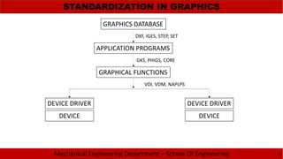
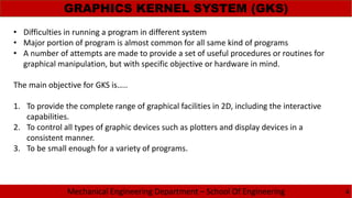
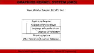
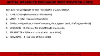

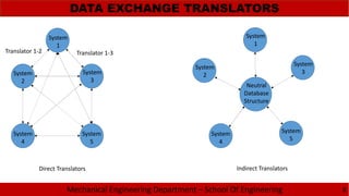
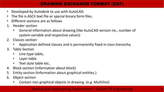

The document discusses the need for standardization in graphics for mechanical engineering, emphasizing the importance of interface standards like GKS, PHIGS, IGES, STEP, and DXF for hardware compatibility and software interoperability. It outlines the functions and structure of key graphics standards, including the detailed sections of IGES and the application of STEP in the engineering lifecycle. Additionally, the document describes the Drawing Exchange Format (DXF) developed by Autodesk, detailing its components and structure for data exchange in CAD applications.