Downloaded 159 times


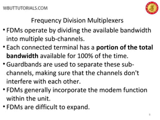


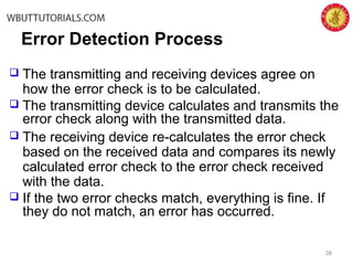


This document discusses various data communication techniques including packetization, multiplexing, and switching. It describes how data is divided into packets with header information added. It explains different types of multiplexing including frequency division, time division, and statistical time division. It also covers circuit switching versus packet switching and different error control techniques such as parity checks, checksums, and cyclic redundancy checks used to detect errors.