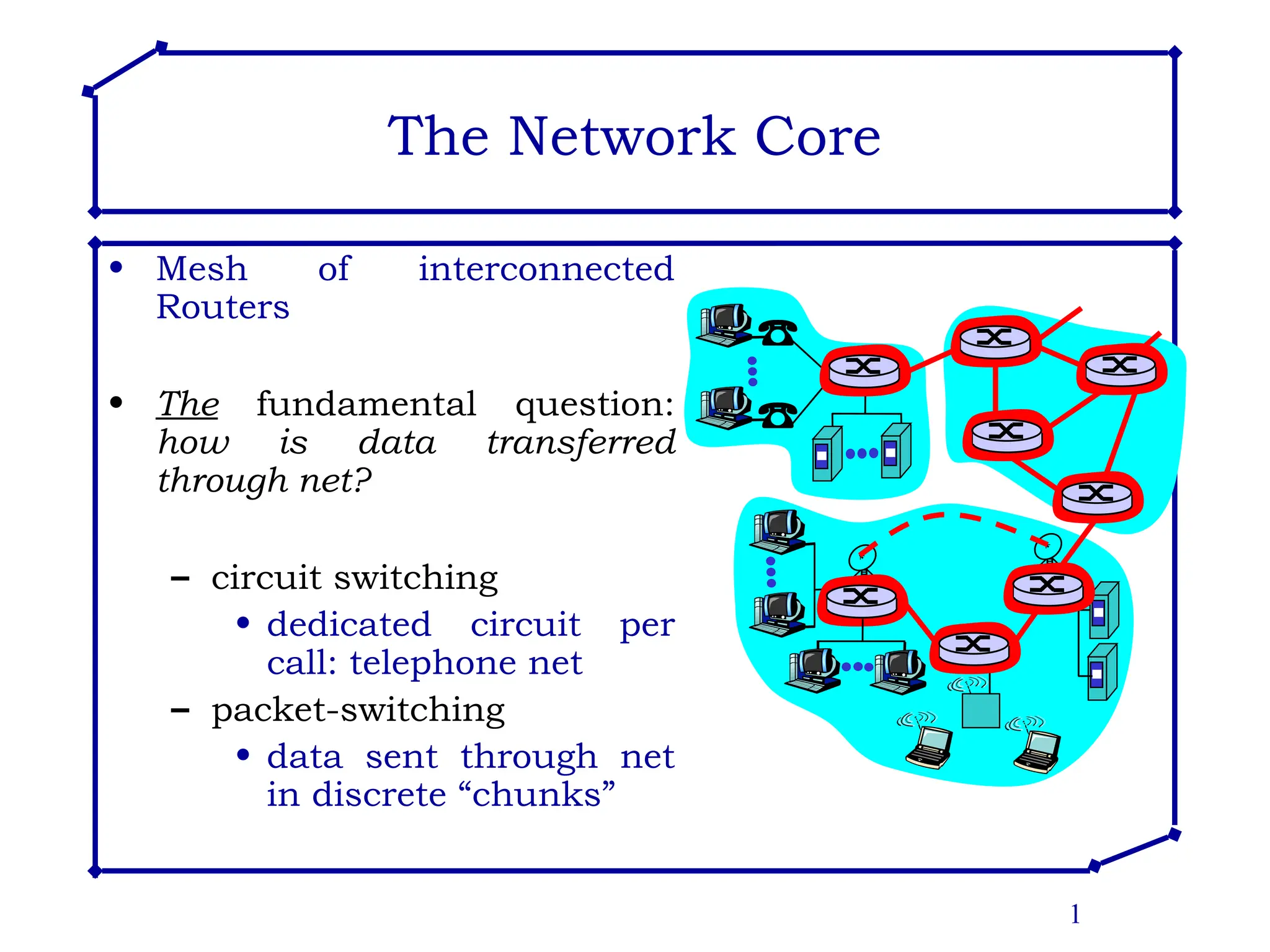
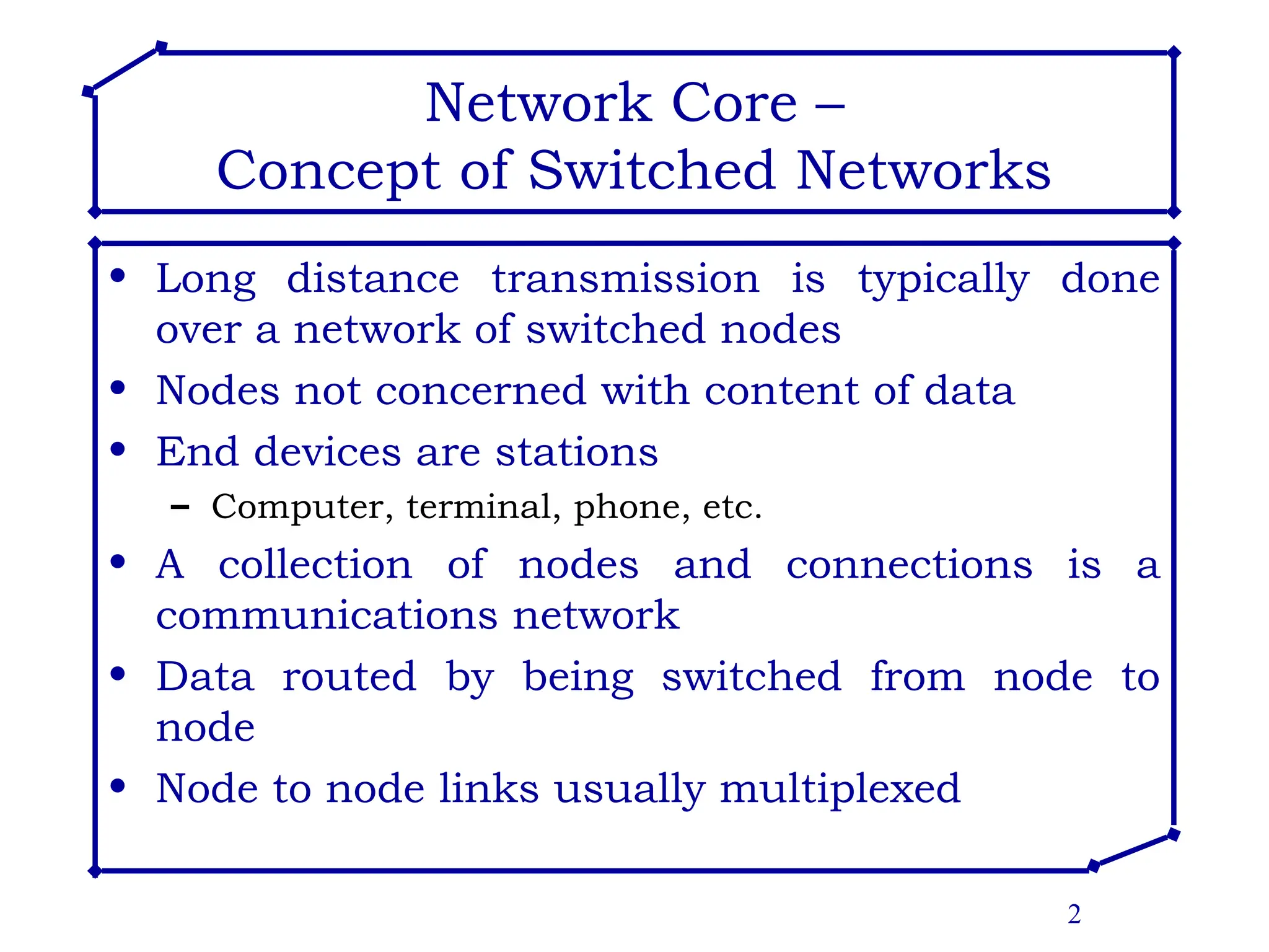
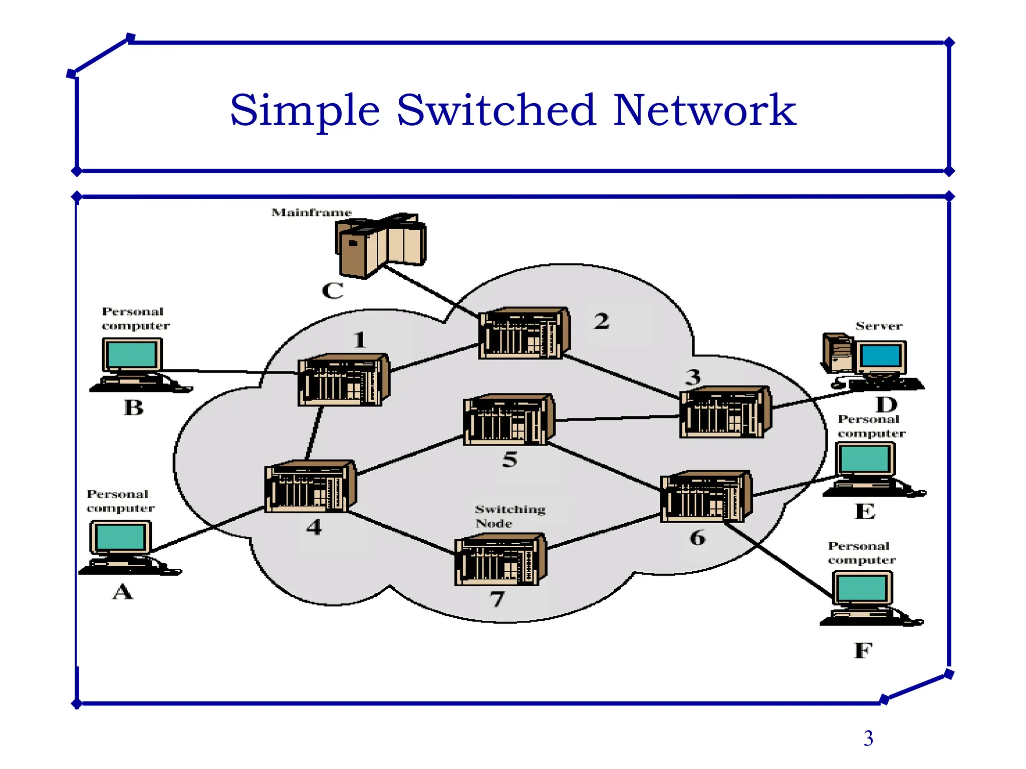
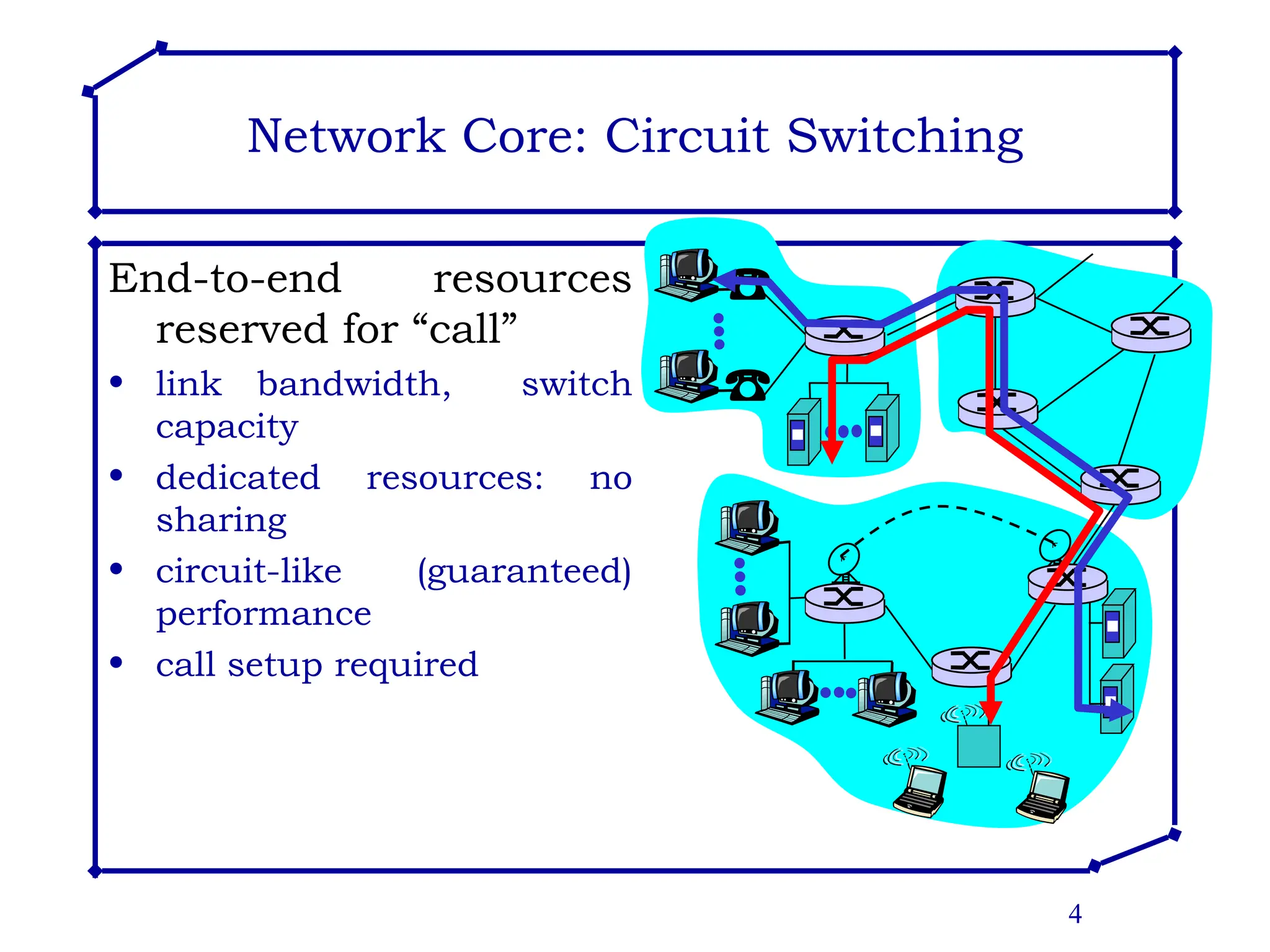
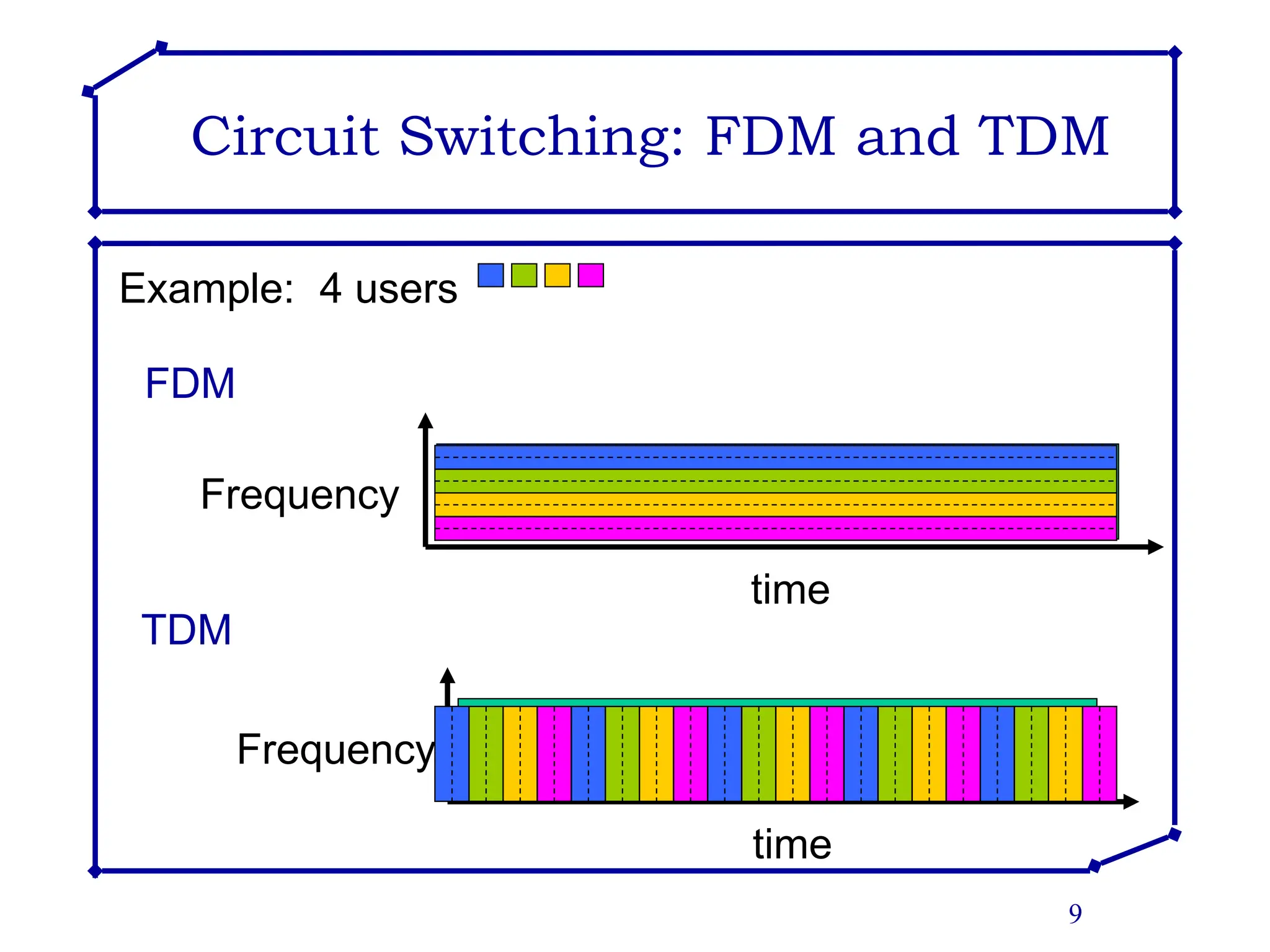
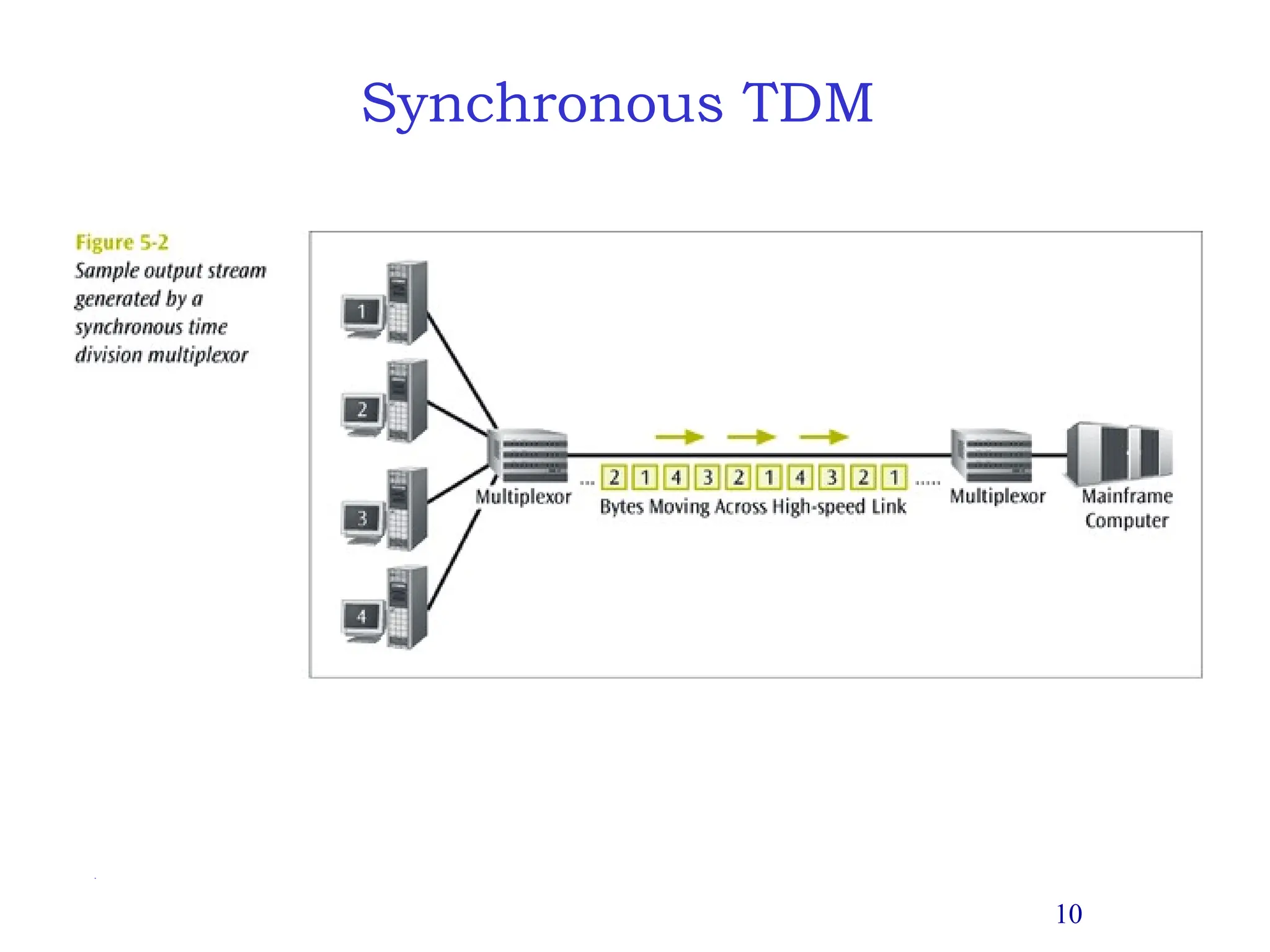
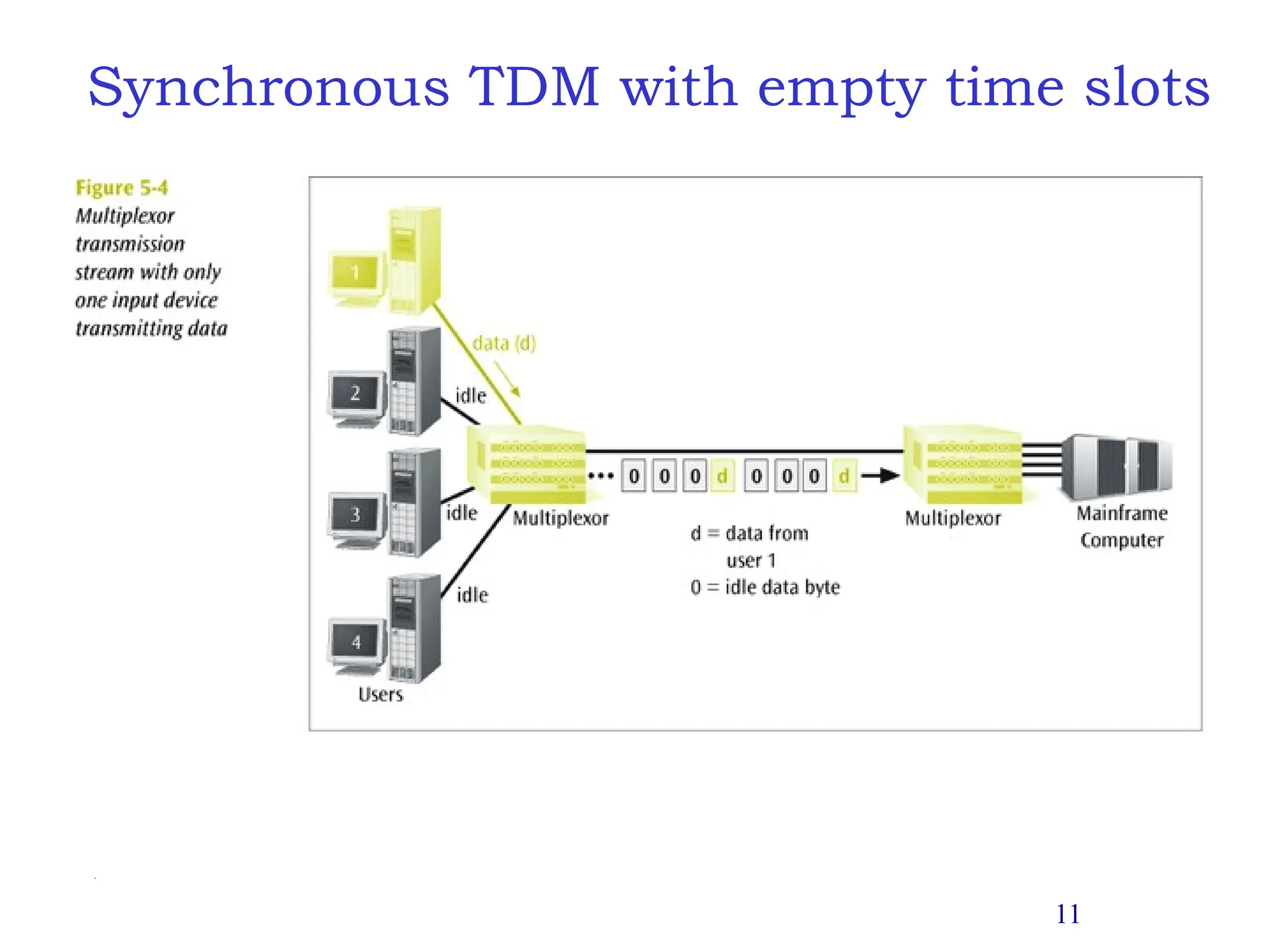
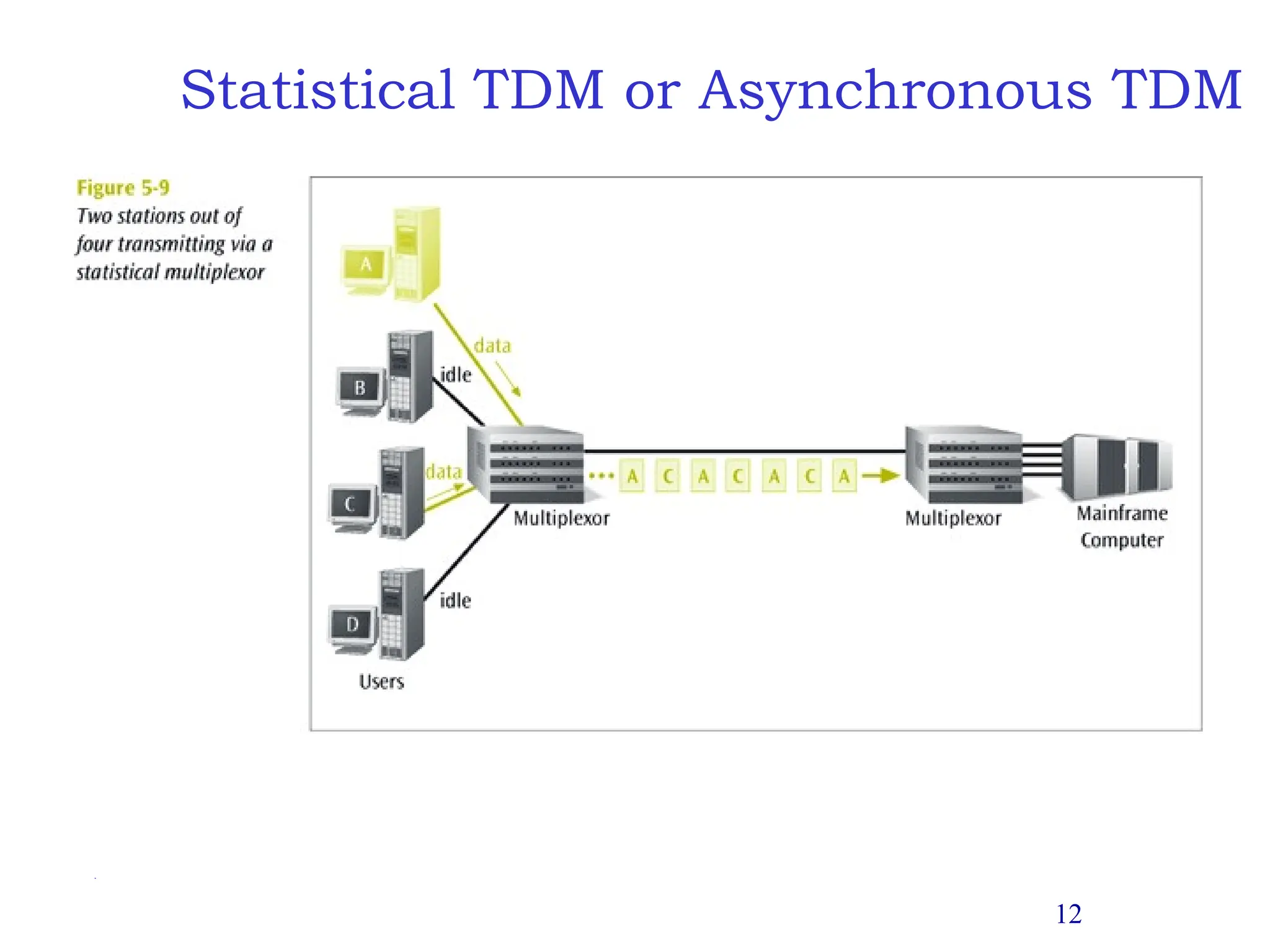
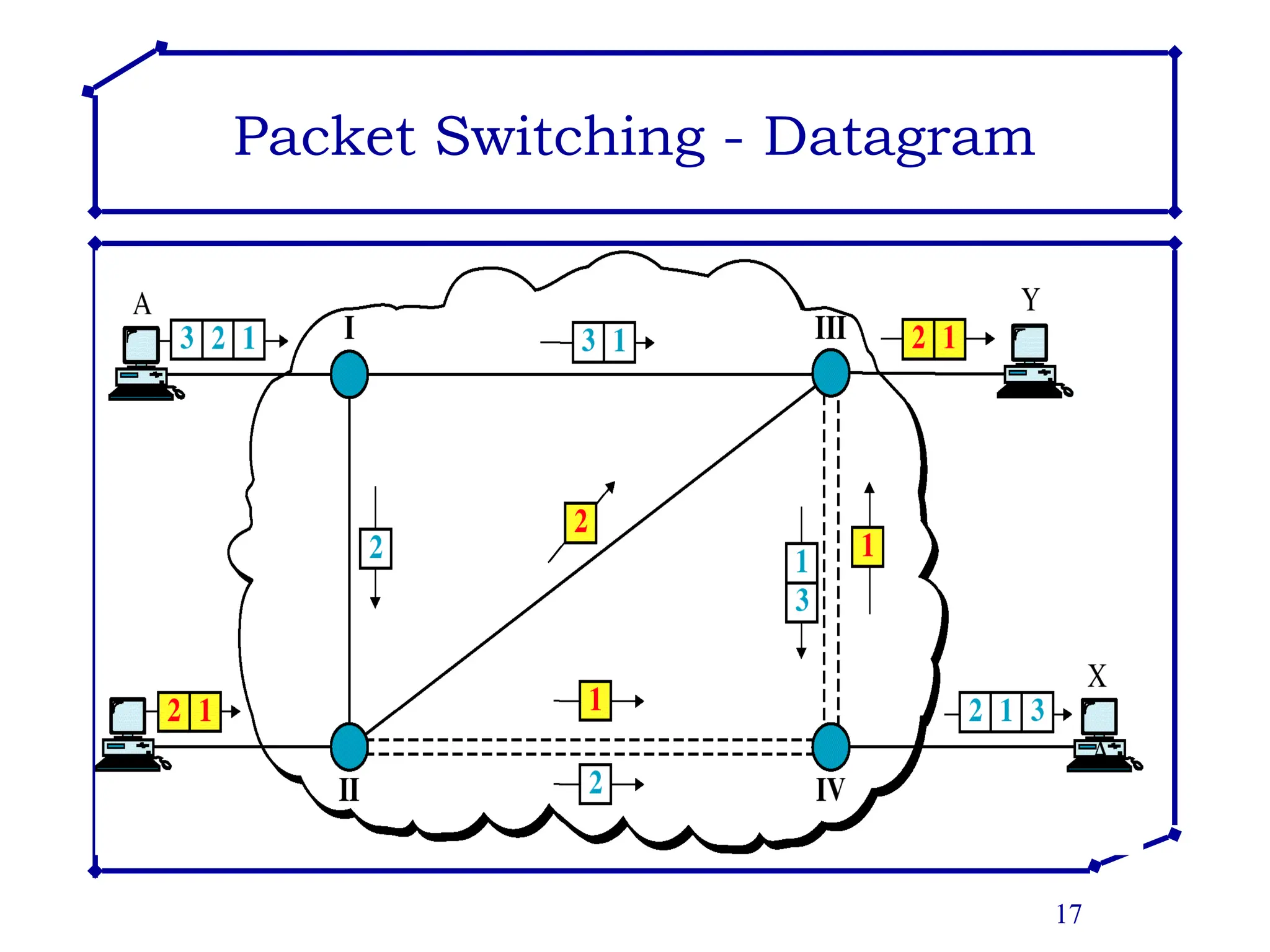
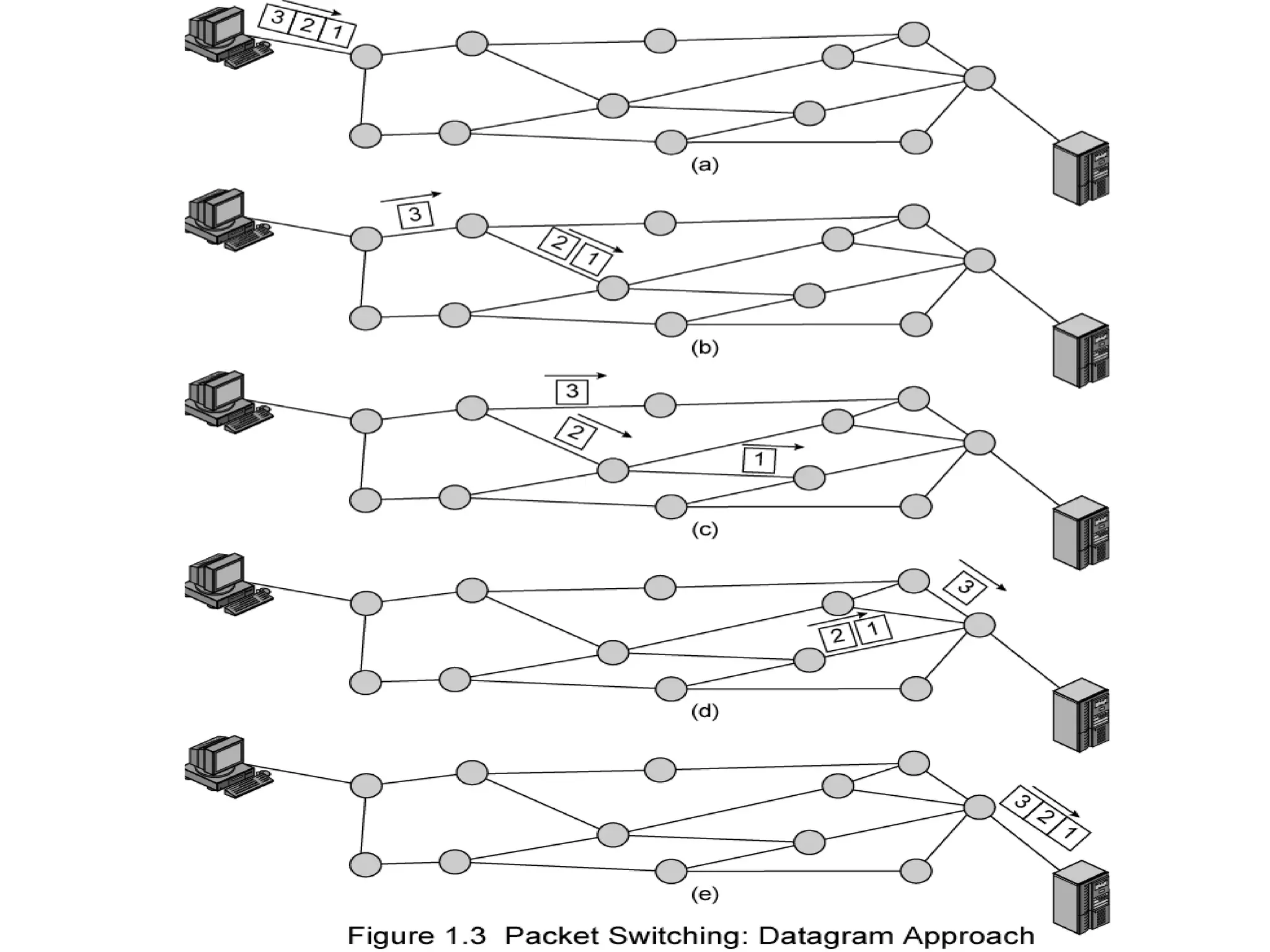
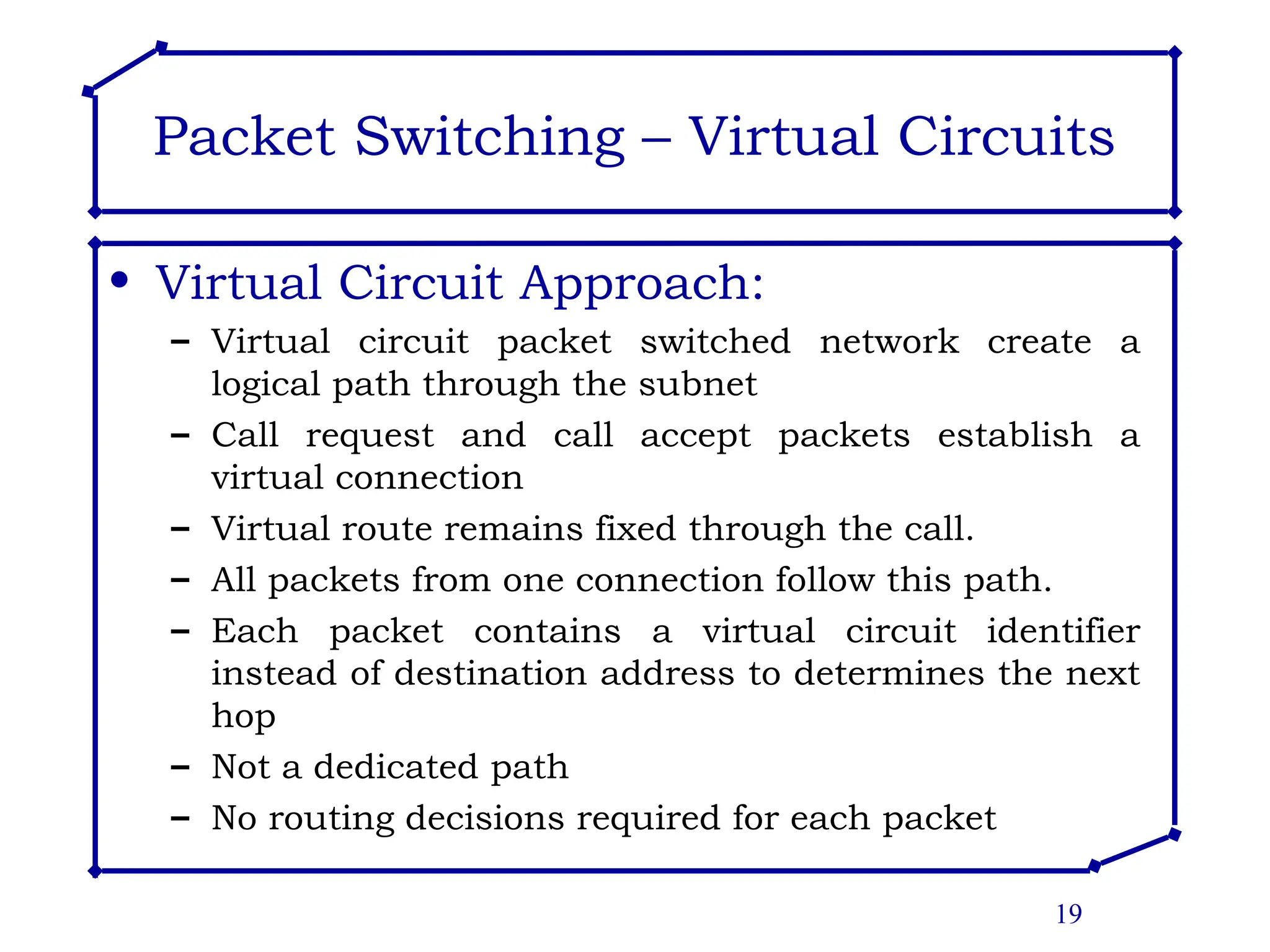
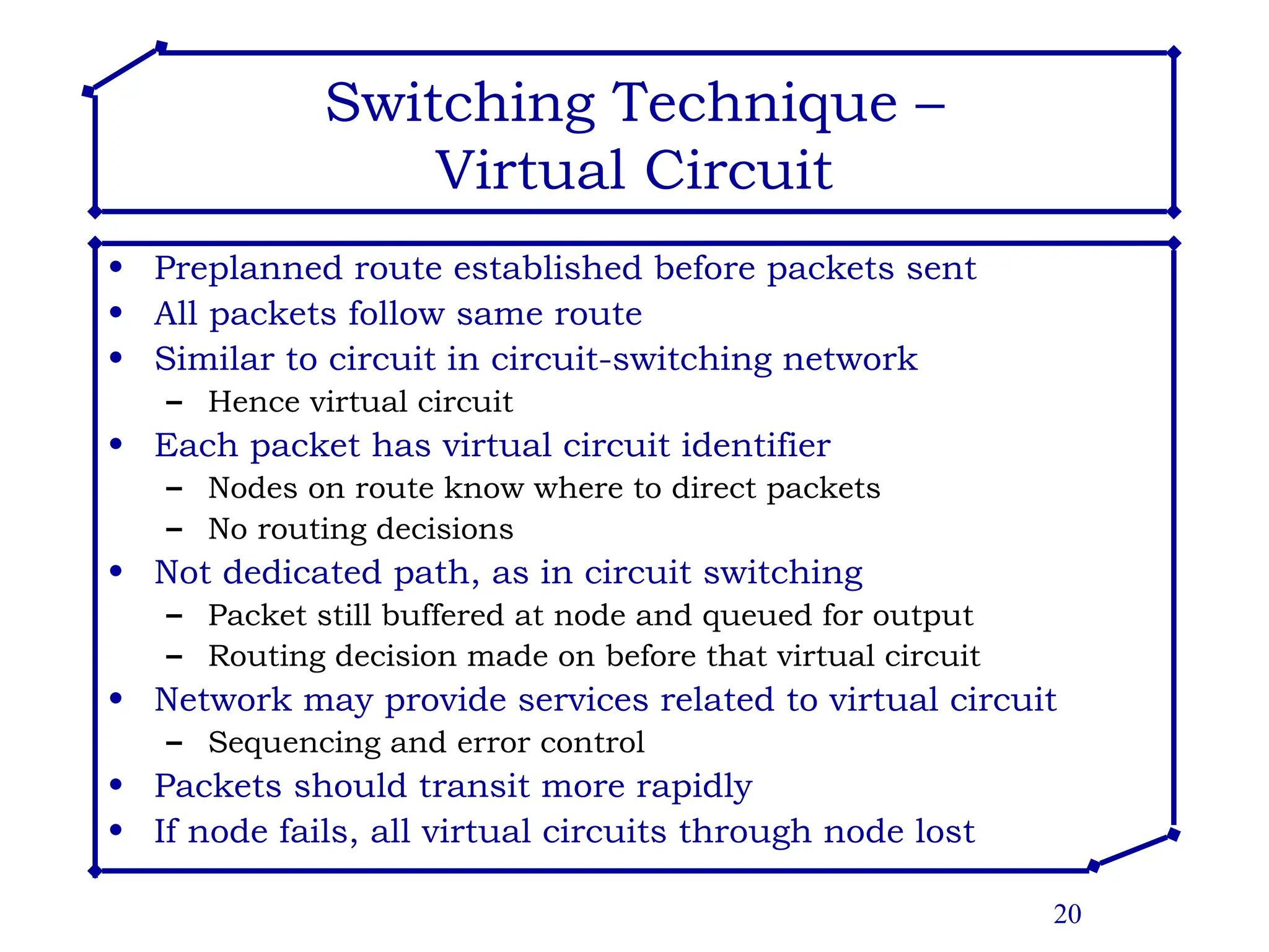
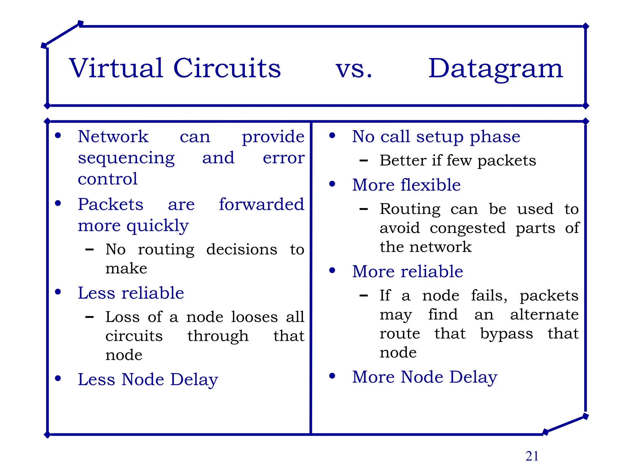
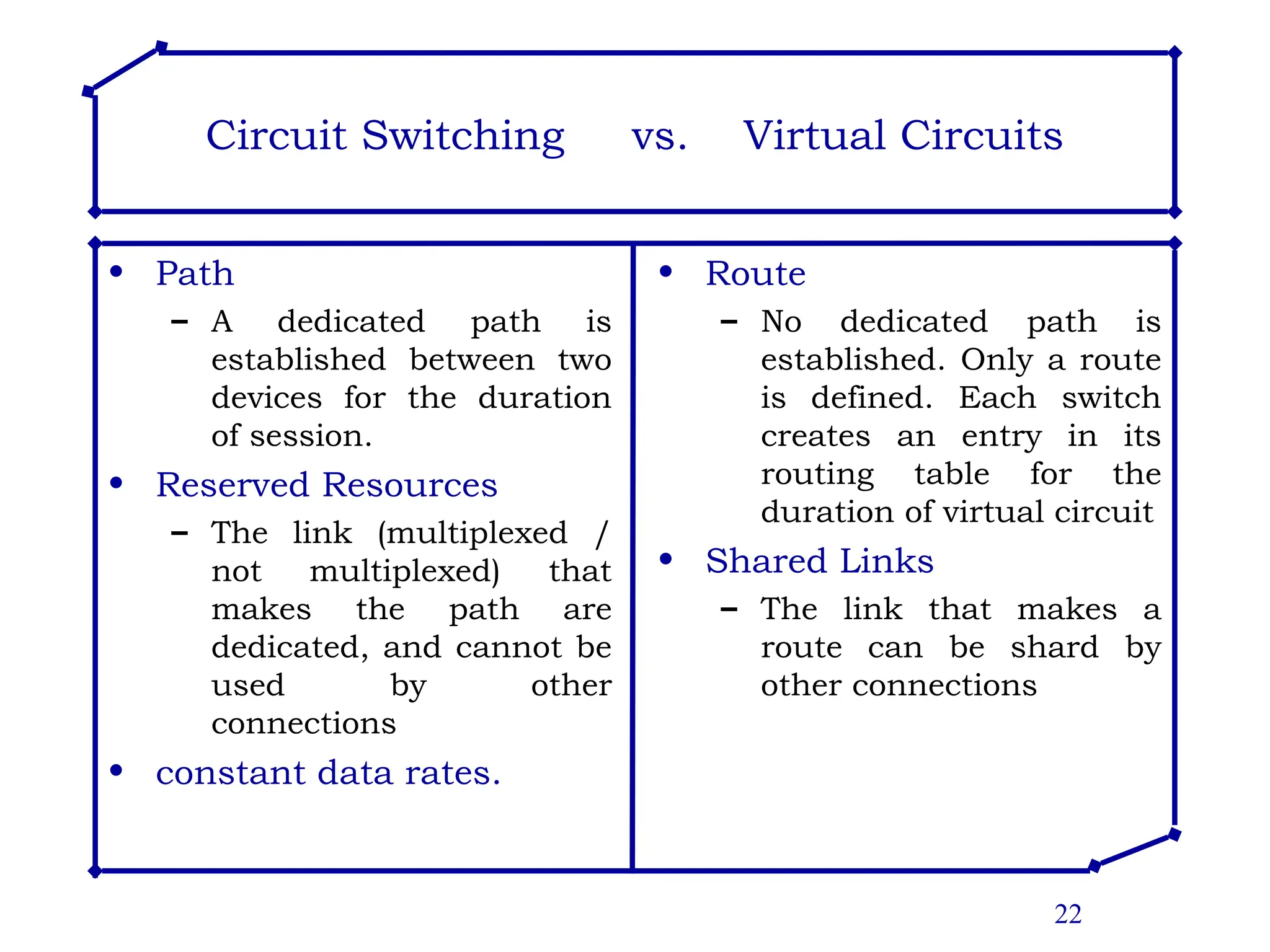
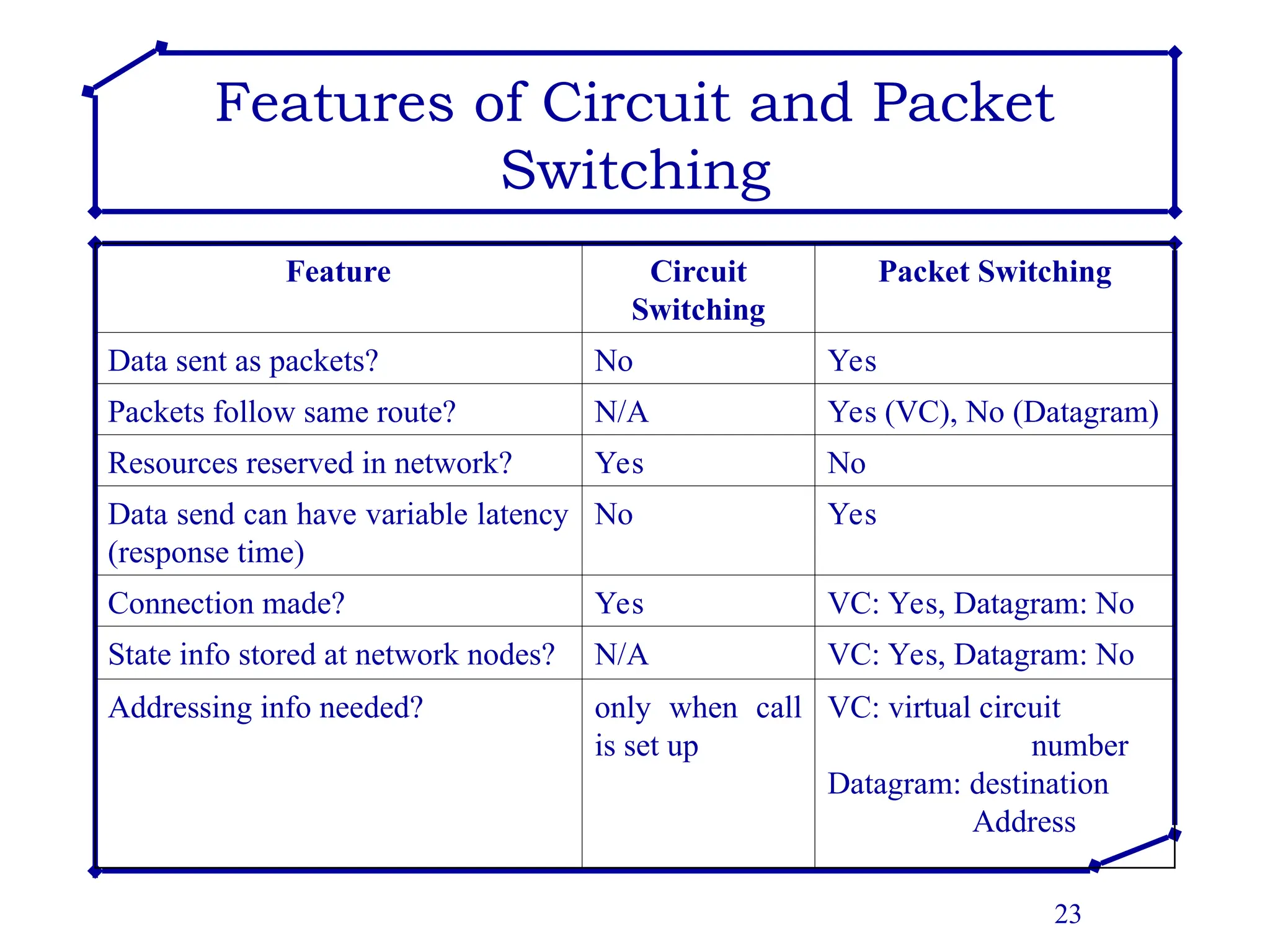
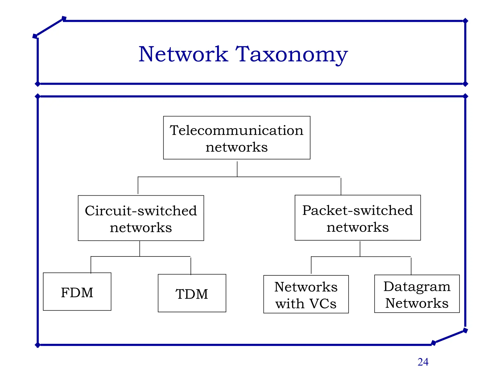
1
The Network Core
• Mesh of interconnected
Routers
• The fundamental question:
how is data transferred
through net?
– circuit switching
• dedicated circuit per
call: telephone net
– packet-switching
• data sent through net
in discrete “chunks”
2
Network Core –
Concept of Switched Networks
• Long distance transmission is typically done
over a network of switched nodes
• Nodes not concerned with content of data
• End devices are stations
– Computer, terminal, phone, etc.
• A collection of nodes and connections is a
communications network
• Data routed by being switched from node to
node
• Node to node links usually multiplexed
3
Simple Switched Network
4
Network Core: Circuit Switching
End-to-end resources
reserved for “call”
• link bandwidth, switch
capacity
• dedicated resources: no
sharing
• circuit-like (guaranteed)
performance
• call setup required
5
Network Core – Circuit Switching
• Switched circuits allow data connections that
can be initiated when needed and terminated
when communication is complete
• Circuit switched network - a network in which a
dedicated circuit is established between sender
and receiver and all data passes over this
circuit.
• The telephone system is a common example.
• The connection is dedicated until one party or
another terminates the connection.
6
Circuit Switching
7
Network Core – Circuit Switching
• Dedicated communication path between two
stations
• Three phases (Establish, Transfer, Disconnect)
• Inefficient (for data traffic)
– Channel capacity dedicated for duration of connection
– Much of the time a data connection is idle
– If no data, capacity wasted
• Set up (connection) takes time
– Once connected, transfer is transparent
– Circuit switching designed for voice
– Constant Data rate
• Both ends must operate at the same rate
8
Network Core - Circuit Switching
• Multiplexing in Circuit Switched Networks
– Multiplexing is a technique, in which a single
transmission medium is being shared among multiple
users.
• Types of Multiplexing
– Frequency Division Multiplexing FDM
– Time Division Multiplexing TDM
9
Circuit Switching: FDM and TDM
FDM
Frequency
time
TDM
Frequency
time
4 users
Example:
10
Synchronous TDM
11
Synchronous TDM with empty time slots
12
Statistical TDM or Asynchronous TDM
13
Network Core: Packet Switching
• Packet switched network
– A network in which data is transmitted in the form of
packets
– Multiple users share network resources
– No dedicated bandwidth is allocated
– No resources are reserved, resources used as needed
– Each packet uses full link bandwidth
– Good for bursty traffic, simpler, no call setup
– Packets queued and transmitted as fast as possible
– Packets are accepted even when network is busy,
which causes the delivery to slow down
14
Network Core: Packet Switching
• The goal of packet switching is to move
packets through routers from source to
destination
• Packets sent one at a time to the network
• Two approaches are used:
– Datagram Approach
– Virtual Circuits Approach
15
Packet Switching - Datagram
• Datagram Approach:
– Each packet is treated independently
– No reference to packets that have gone before
– Each node chooses next node on path using
destination address
– Packets with same destination address may not follow
same route
– Packets may arrive out of sequence, may be lost
– It is up to receiver to re-order packets and recover
from lost packets
– No Call setup
– For an exchange of a few packets, datagram quicker
– Analogy: driving, asking directions
16
Packet Switching - Datagram
• The Internet is a Datagram network
• Datagram network is not either connection-
oriented or connectionless.
• Internet provides both connection-oriented
(TCP) and connectionless services (UDP) to
applications.
17
Packet Switching - Datagram
IT-5302-3 Internet Architecture and Protocols, PUCIT, University of the Punjab, Pakistan
18
19
Packet Switching – Virtual Circuits
• Virtual Circuit Approach:
– Virtual circuit packet switched network create a
logical path through the subnet
– Call request and call accept packets establish a
virtual connection
– Virtual route remains fixed through the call.
– All packets from one connection follow this path.
– Each packet contains a virtual circuit identifier
instead of destination address to determines the next
hop
– Not a dedicated path
– No routing decisions required for each packet
20
Switching Technique –
Virtual Circuit
• Preplanned route established before packets sent
• All packets follow same route
• Similar to circuit in circuit-switching network
– Hence virtual circuit
• Each packet has virtual circuit identifier
– Nodes on route know where to direct packets
– No routing decisions
• Not dedicated path, as in circuit switching
– Packet still buffered at node and queued for output
– Routing decision made on before that virtual circuit
• Network may provide services related to virtual circuit
– Sequencing and error control
• Packets should transit more rapidly
• If node fails, all virtual circuits through node lost
21
Virtual Circuits vs. Datagram
• Network can provide
sequencing and error
control
• Packets are forwarded
more quickly
– No routing decisions to
make
• Less reliable
– Loss of a node looses all
circuits through that
node
• Less Node Delay
• No call setup phase
– Better if few packets
• More flexible
– Routing can be used to
avoid congested parts of
the network
• More reliable
– If a node fails, packets
may find an alternate
route that bypass that
node
• More Node Delay
22
Circuit Switching vs. Virtual Circuits
• Path
– A dedicated path is
established between two
devices for the duration
of session.
• Reserved Resources
– The link (multiplexed /
not multiplexed) that
makes the path are
dedicated, and cannot be
used by other
connections
• constant data rates.
• Route
– No dedicated path is
established. Only a route
is defined. Each switch
creates an entry in its
routing table for the
duration of virtual circuit
• Shared Links
– The link that makes a
route can be shard by
other connections
23
Features of Circuit and Packet
Switching
Feature Circuit
Switching
Packet Switching
Data sent as packets? No Yes
Packets follow same route? N/A Yes (VC), No (Datagram)
Resources reserved in network? Yes No
Data send can have variable latency
(response time)
No Yes
Connection made? Yes VC: Yes, Datagram: No
State info stored at network nodes? N/A VC: Yes, Datagram: No
Addressing info needed? only when call
is set up
VC: virtual circuit
number
Datagram: destination
Address
24
Network Taxonomy
Telecommunication
networks
Circuit-switched
networks
FDM TDM
Packet-switched
networks
Networks
with VCs
Datagram
Networks

Circuit switching in operational research

  • 1.
    1 The Network Core •Mesh of interconnected Routers • The fundamental question: how is data transferred through net? – circuit switching • dedicated circuit per call: telephone net – packet-switching • data sent through net in discrete “chunks”
  • 2.
    2 Network Core – Conceptof Switched Networks • Long distance transmission is typically done over a network of switched nodes • Nodes not concerned with content of data • End devices are stations – Computer, terminal, phone, etc. • A collection of nodes and connections is a communications network • Data routed by being switched from node to node • Node to node links usually multiplexed
  • 3.
  • 4.
    4 Network Core: CircuitSwitching End-to-end resources reserved for “call” • link bandwidth, switch capacity • dedicated resources: no sharing • circuit-like (guaranteed) performance • call setup required
  • 5.
    5 Network Core –Circuit Switching • Switched circuits allow data connections that can be initiated when needed and terminated when communication is complete • Circuit switched network - a network in which a dedicated circuit is established between sender and receiver and all data passes over this circuit. • The telephone system is a common example. • The connection is dedicated until one party or another terminates the connection.
  • 6.
  • 7.
    7 Network Core –Circuit Switching • Dedicated communication path between two stations • Three phases (Establish, Transfer, Disconnect) • Inefficient (for data traffic) – Channel capacity dedicated for duration of connection – Much of the time a data connection is idle – If no data, capacity wasted • Set up (connection) takes time – Once connected, transfer is transparent – Circuit switching designed for voice – Constant Data rate • Both ends must operate at the same rate
  • 8.
    8 Network Core -Circuit Switching • Multiplexing in Circuit Switched Networks – Multiplexing is a technique, in which a single transmission medium is being shared among multiple users. • Types of Multiplexing – Frequency Division Multiplexing FDM – Time Division Multiplexing TDM
  • 9.
    9 Circuit Switching: FDMand TDM FDM Frequency time TDM Frequency time 4 users Example:
  • 10.
  • 11.
    11 Synchronous TDM withempty time slots
  • 12.
    12 Statistical TDM orAsynchronous TDM
  • 13.
    13 Network Core: PacketSwitching • Packet switched network – A network in which data is transmitted in the form of packets – Multiple users share network resources – No dedicated bandwidth is allocated – No resources are reserved, resources used as needed – Each packet uses full link bandwidth – Good for bursty traffic, simpler, no call setup – Packets queued and transmitted as fast as possible – Packets are accepted even when network is busy, which causes the delivery to slow down
  • 14.
    14 Network Core: PacketSwitching • The goal of packet switching is to move packets through routers from source to destination • Packets sent one at a time to the network • Two approaches are used: – Datagram Approach – Virtual Circuits Approach
  • 15.
    15 Packet Switching -Datagram • Datagram Approach: – Each packet is treated independently – No reference to packets that have gone before – Each node chooses next node on path using destination address – Packets with same destination address may not follow same route – Packets may arrive out of sequence, may be lost – It is up to receiver to re-order packets and recover from lost packets – No Call setup – For an exchange of a few packets, datagram quicker – Analogy: driving, asking directions
  • 16.
    16 Packet Switching -Datagram • The Internet is a Datagram network • Datagram network is not either connection- oriented or connectionless. • Internet provides both connection-oriented (TCP) and connectionless services (UDP) to applications.
  • 17.
  • 18.
    IT-5302-3 Internet Architectureand Protocols, PUCIT, University of the Punjab, Pakistan 18
  • 19.
    19 Packet Switching –Virtual Circuits • Virtual Circuit Approach: – Virtual circuit packet switched network create a logical path through the subnet – Call request and call accept packets establish a virtual connection – Virtual route remains fixed through the call. – All packets from one connection follow this path. – Each packet contains a virtual circuit identifier instead of destination address to determines the next hop – Not a dedicated path – No routing decisions required for each packet
  • 20.
    20 Switching Technique – VirtualCircuit • Preplanned route established before packets sent • All packets follow same route • Similar to circuit in circuit-switching network – Hence virtual circuit • Each packet has virtual circuit identifier – Nodes on route know where to direct packets – No routing decisions • Not dedicated path, as in circuit switching – Packet still buffered at node and queued for output – Routing decision made on before that virtual circuit • Network may provide services related to virtual circuit – Sequencing and error control • Packets should transit more rapidly • If node fails, all virtual circuits through node lost
  • 21.
    21 Virtual Circuits vs.Datagram • Network can provide sequencing and error control • Packets are forwarded more quickly – No routing decisions to make • Less reliable – Loss of a node looses all circuits through that node • Less Node Delay • No call setup phase – Better if few packets • More flexible – Routing can be used to avoid congested parts of the network • More reliable – If a node fails, packets may find an alternate route that bypass that node • More Node Delay
  • 22.
    22 Circuit Switching vs.Virtual Circuits • Path – A dedicated path is established between two devices for the duration of session. • Reserved Resources – The link (multiplexed / not multiplexed) that makes the path are dedicated, and cannot be used by other connections • constant data rates. • Route – No dedicated path is established. Only a route is defined. Each switch creates an entry in its routing table for the duration of virtual circuit • Shared Links – The link that makes a route can be shard by other connections
  • 23.
    23 Features of Circuitand Packet Switching Feature Circuit Switching Packet Switching Data sent as packets? No Yes Packets follow same route? N/A Yes (VC), No (Datagram) Resources reserved in network? Yes No Data send can have variable latency (response time) No Yes Connection made? Yes VC: Yes, Datagram: No State info stored at network nodes? N/A VC: Yes, Datagram: No Addressing info needed? only when call is set up VC: virtual circuit number Datagram: destination Address
  • 24.

Editor's Notes

  • #9 Two simple multiple access control techniques. Each mobile’s share of the bandwidth is divided into portions for the uplink and the downlink. Also, possibly, out of band signaling. As we will see, used in AMPS, GSM, IS-54/136