Downloaded 721 times
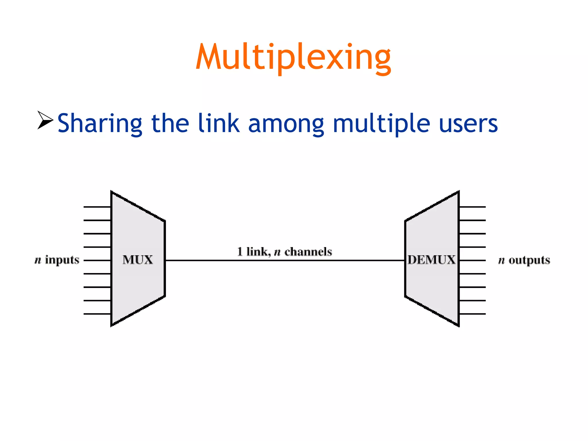
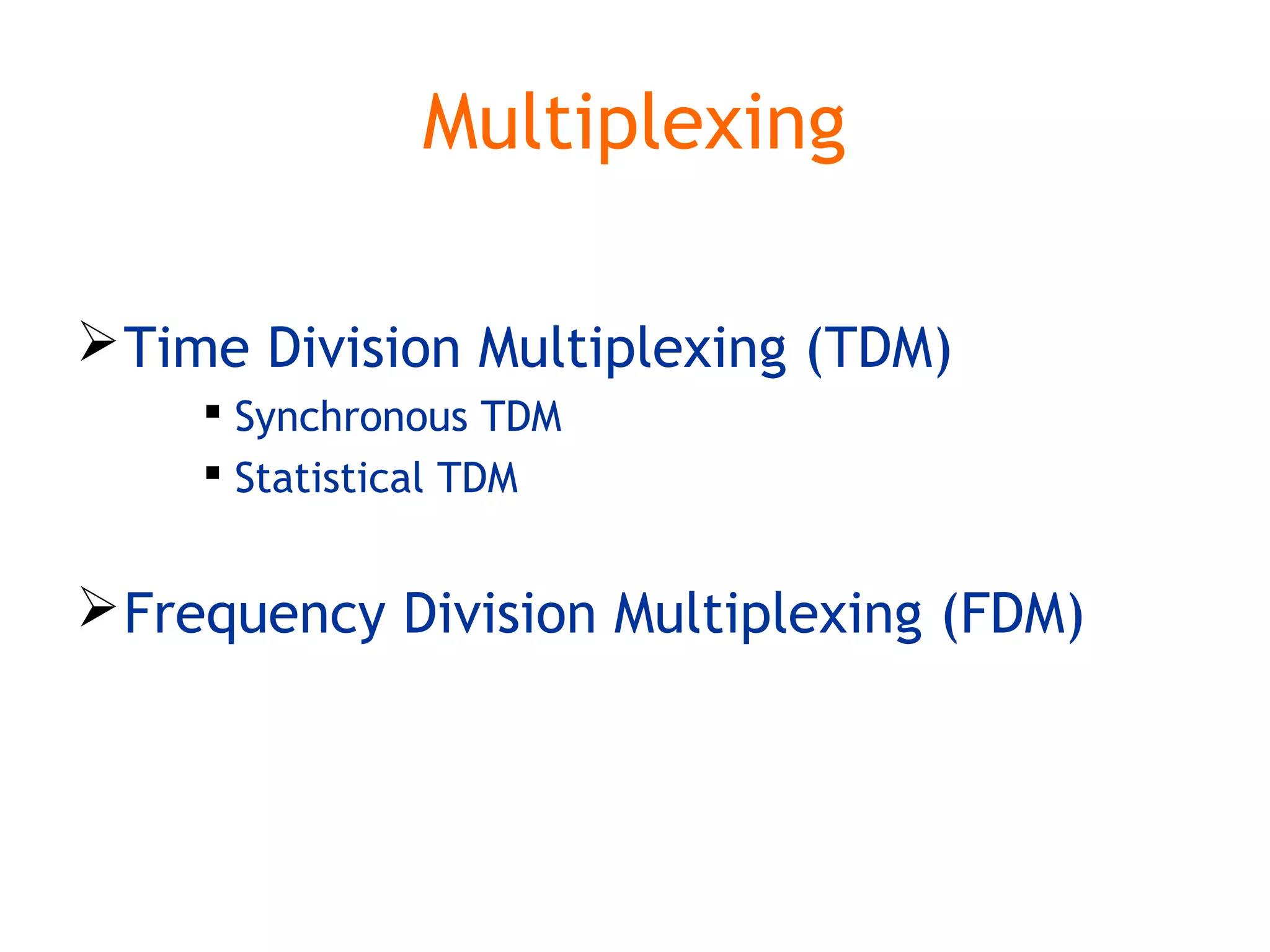
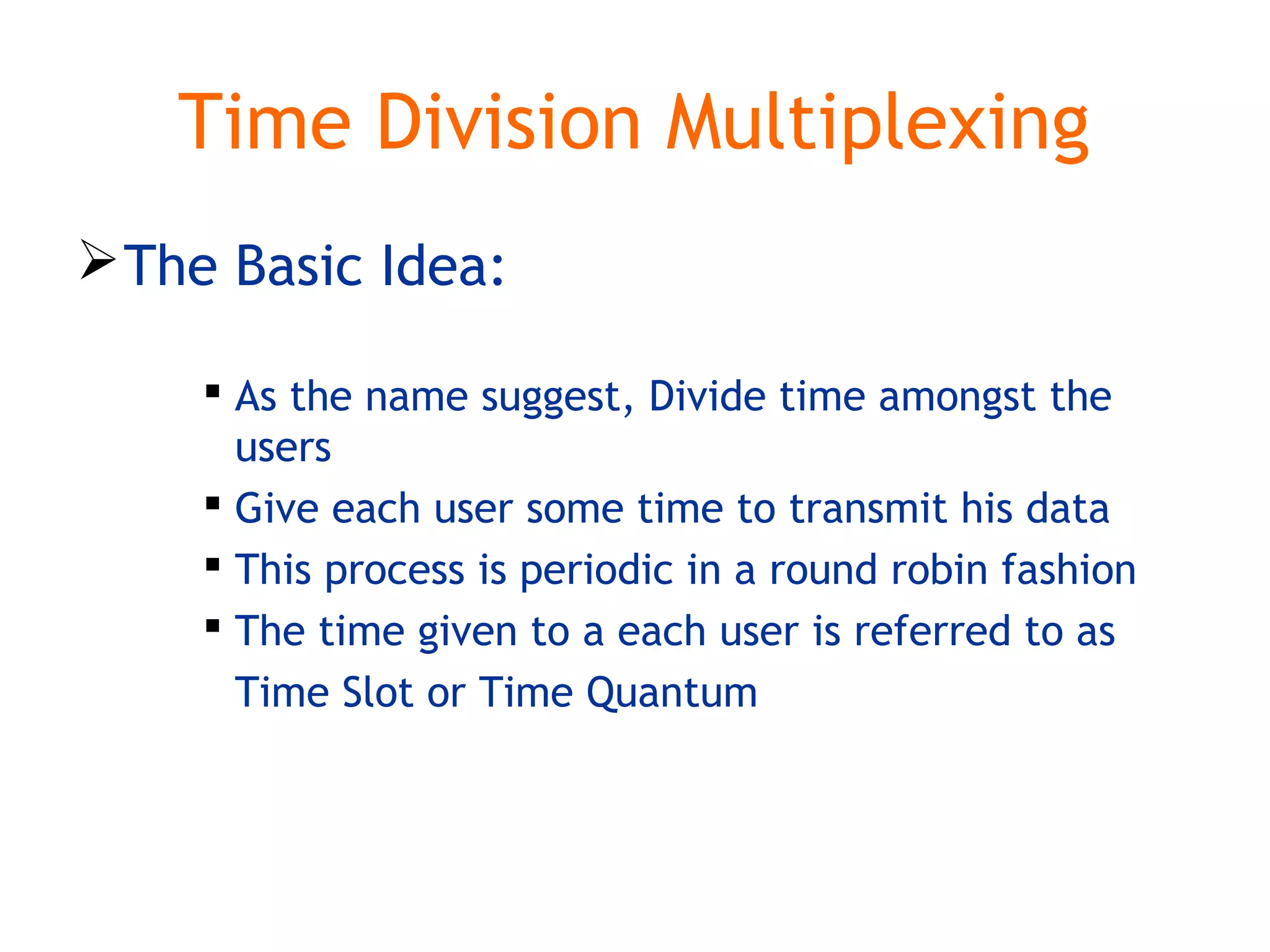
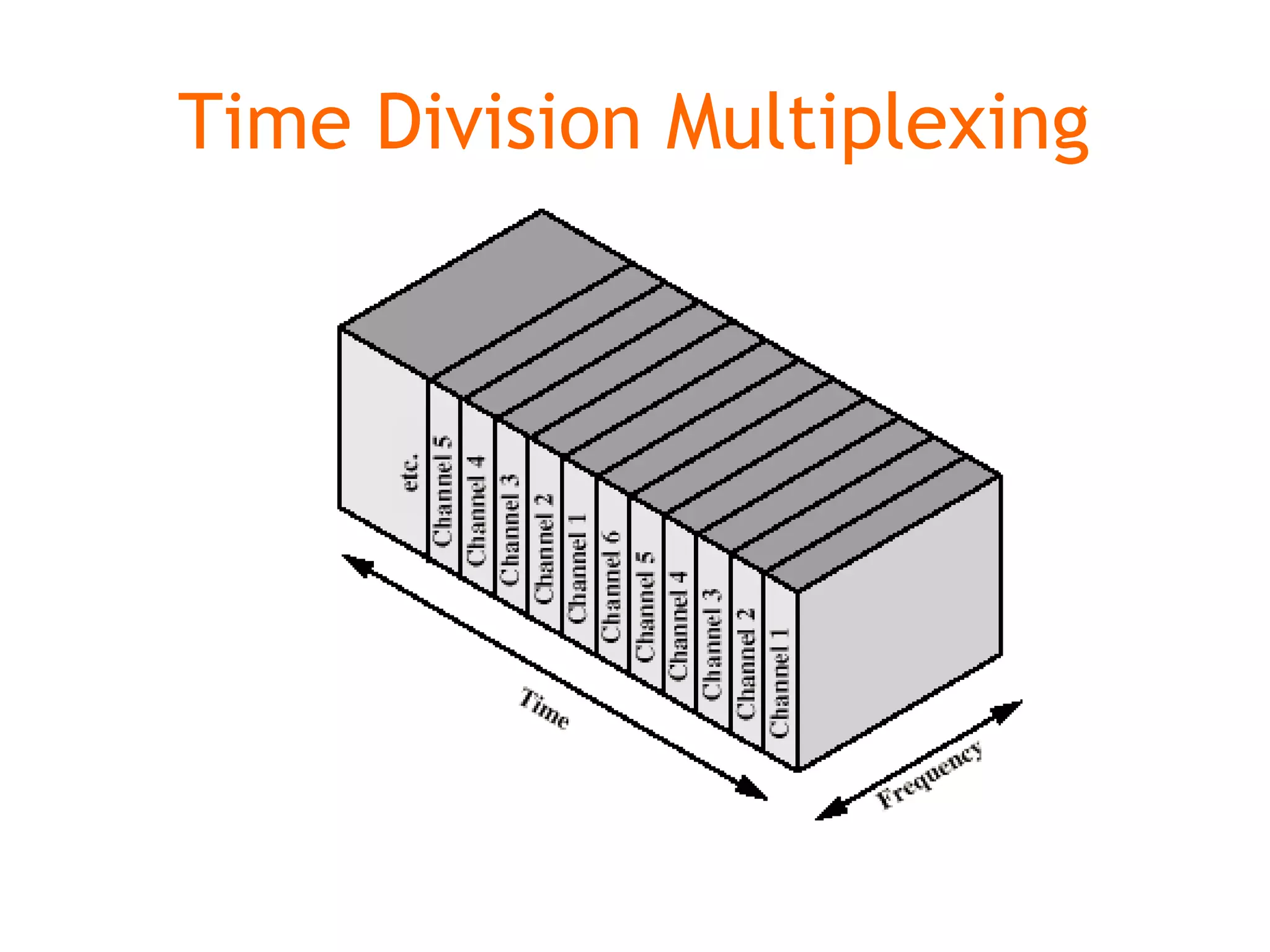
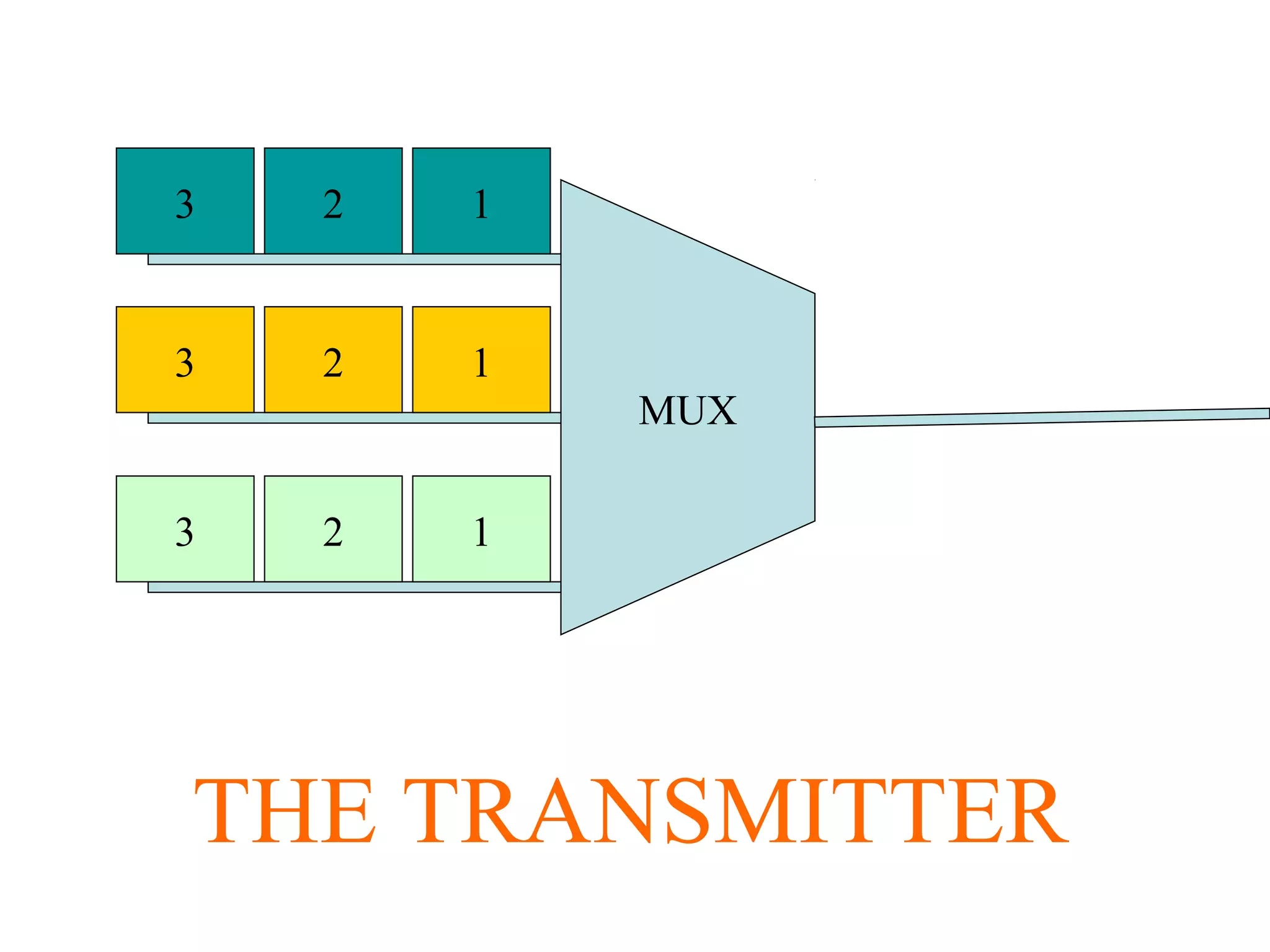
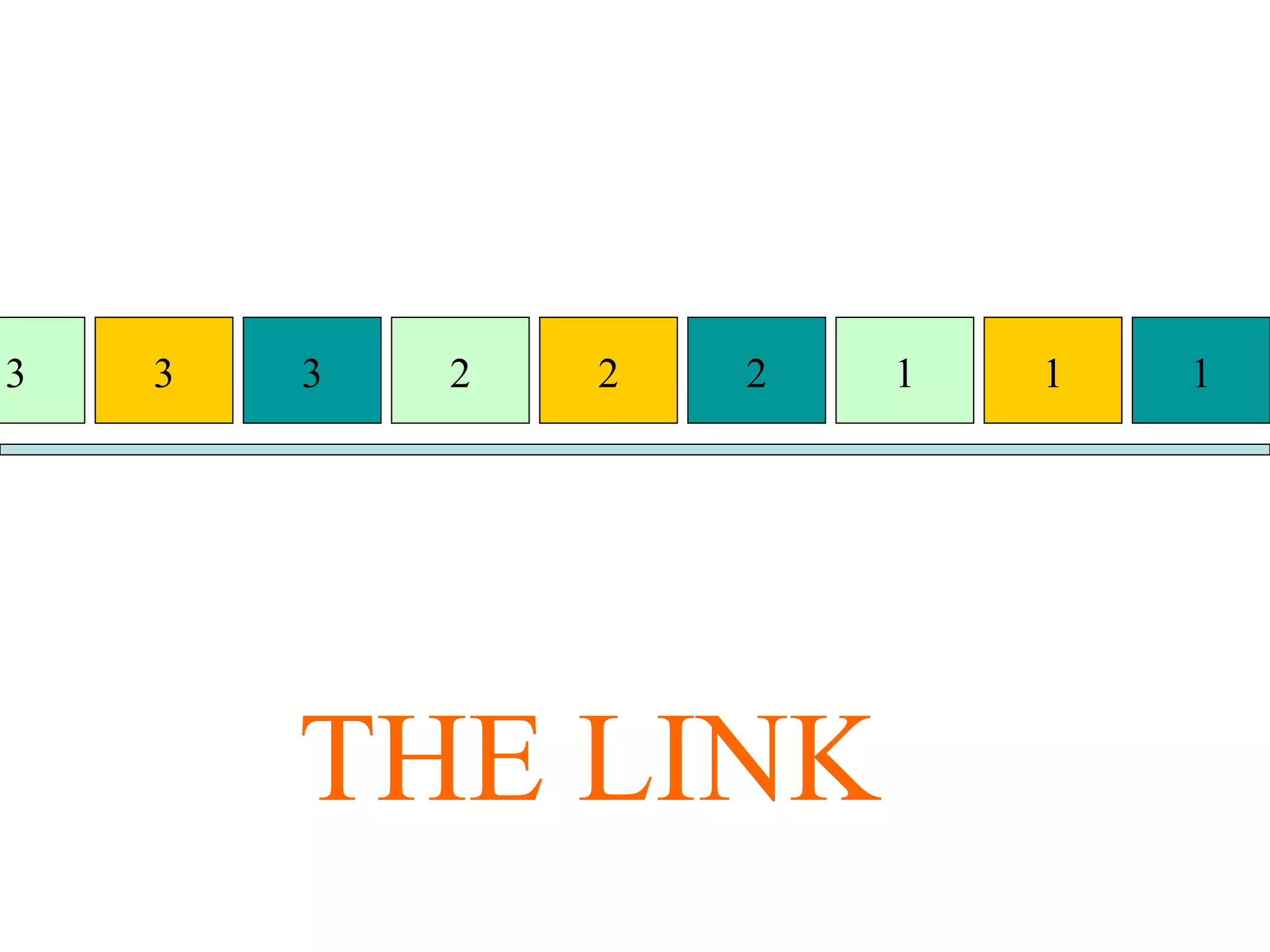
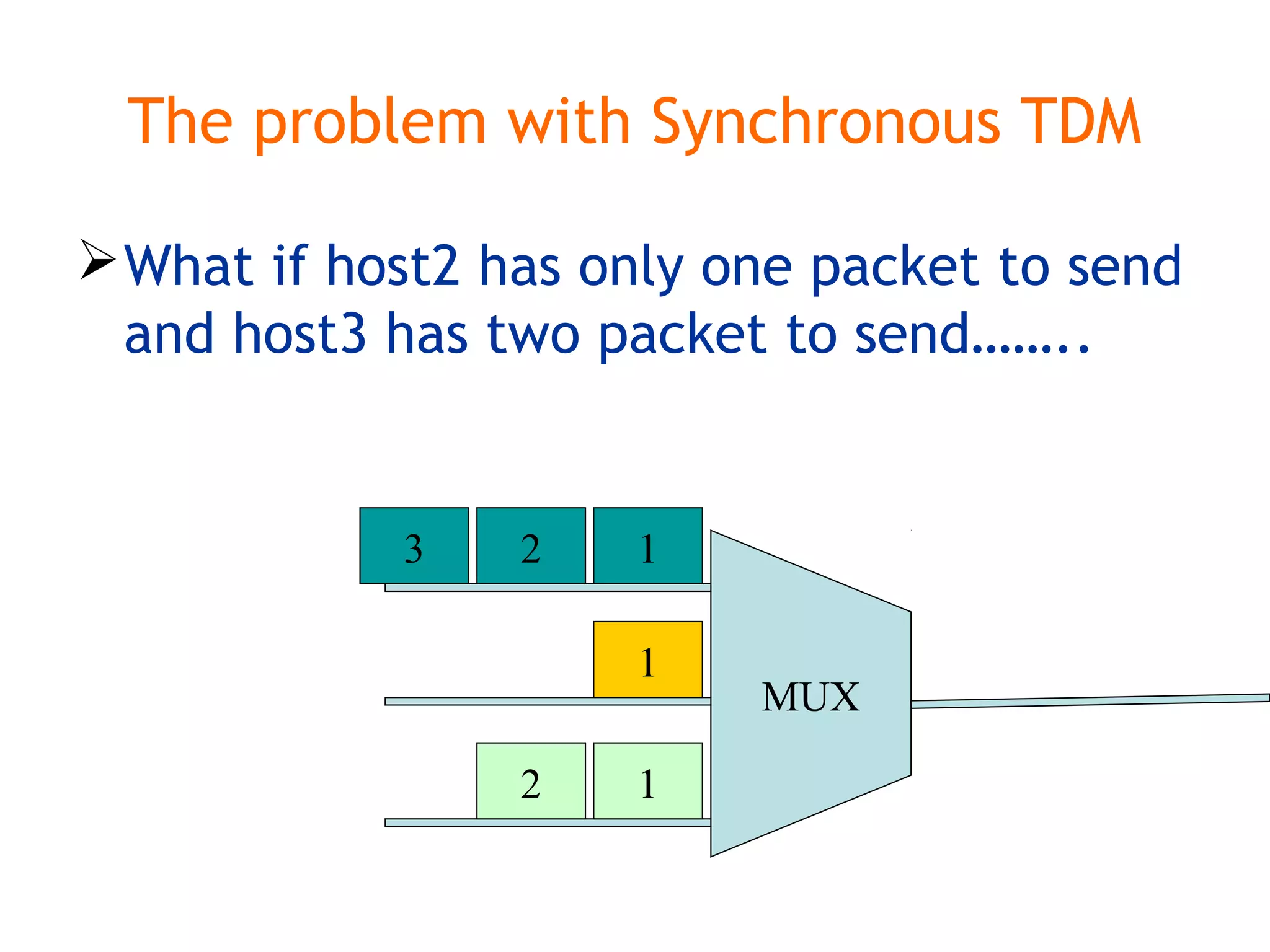
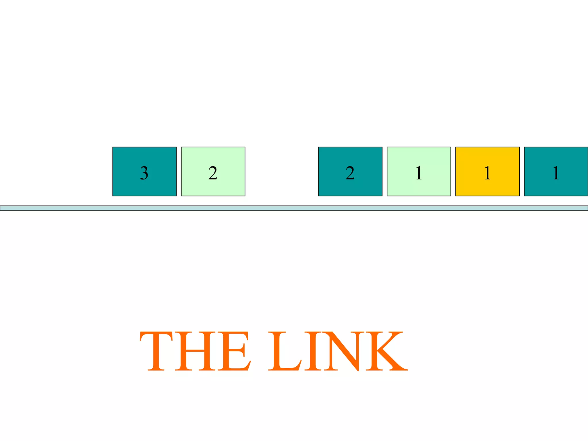

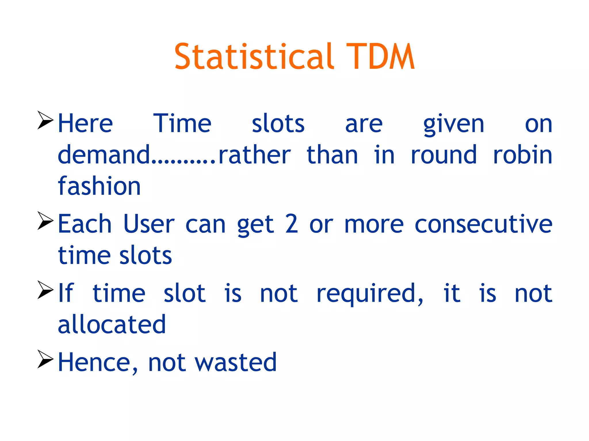
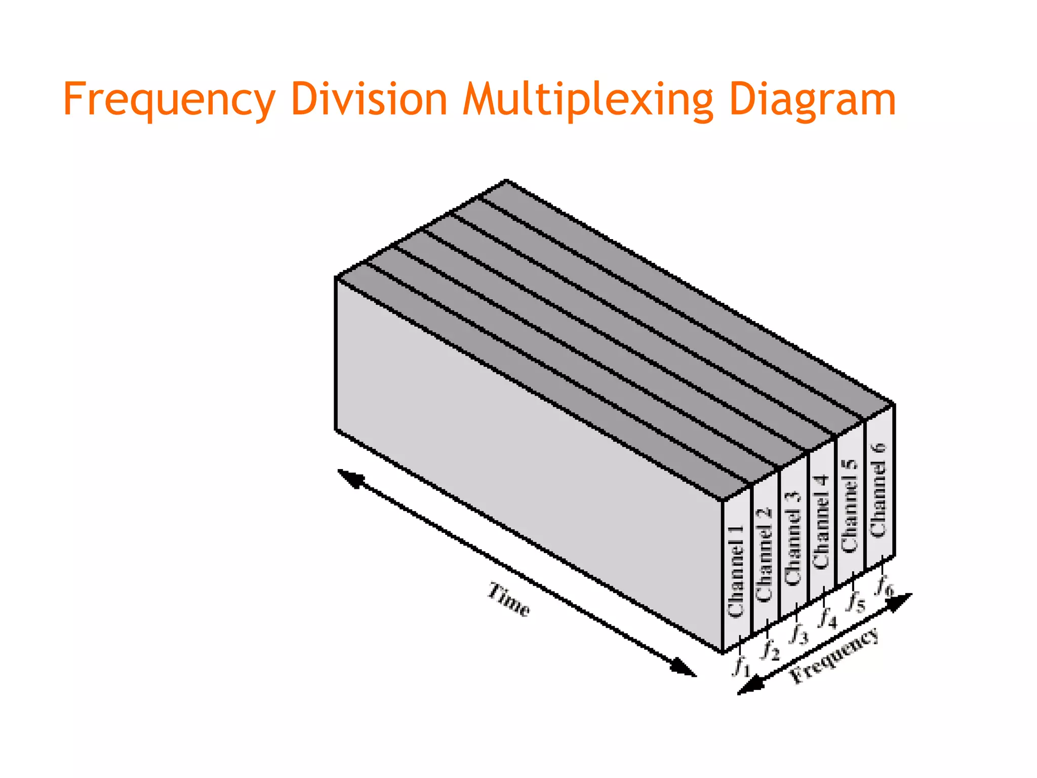
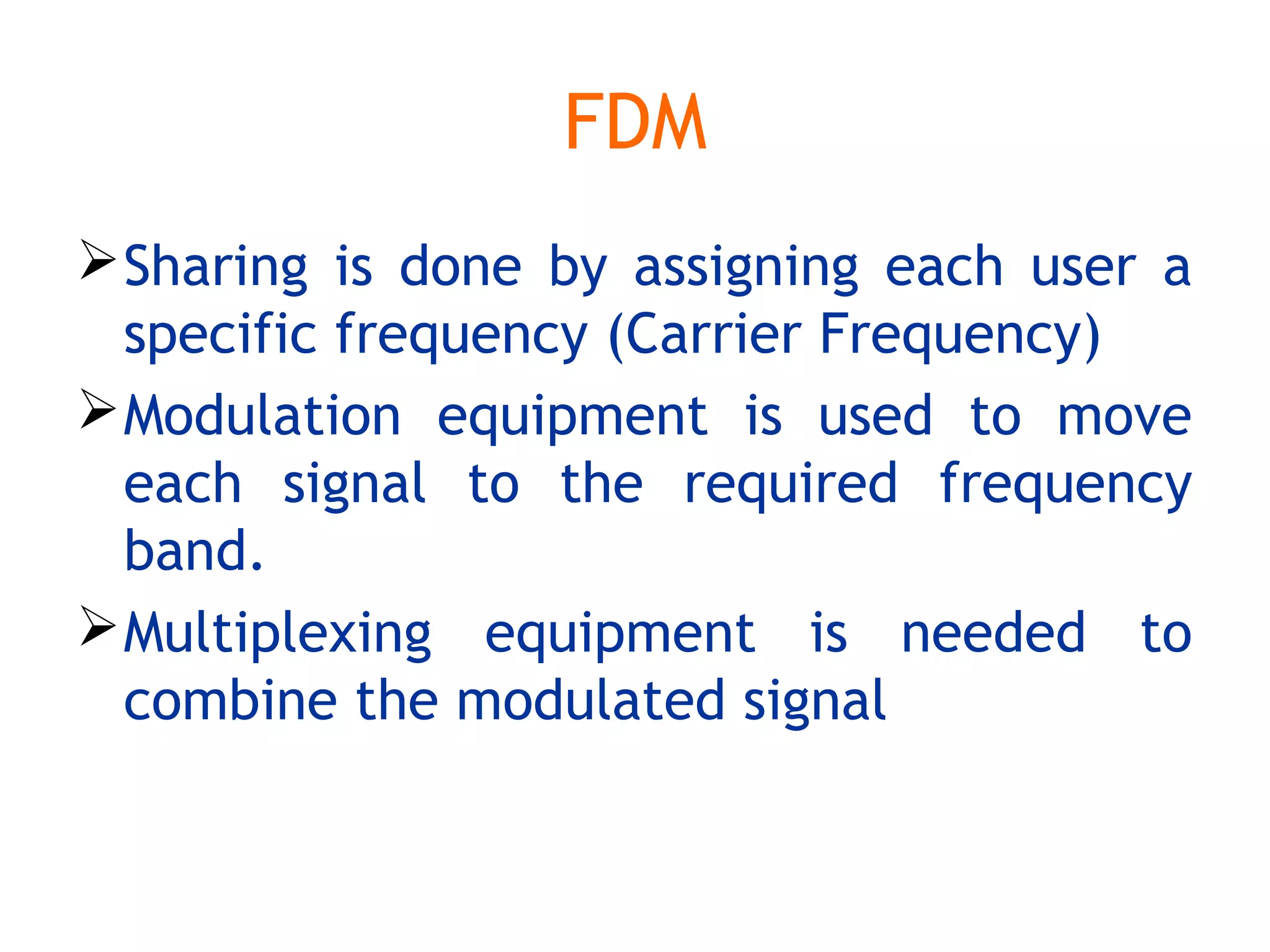
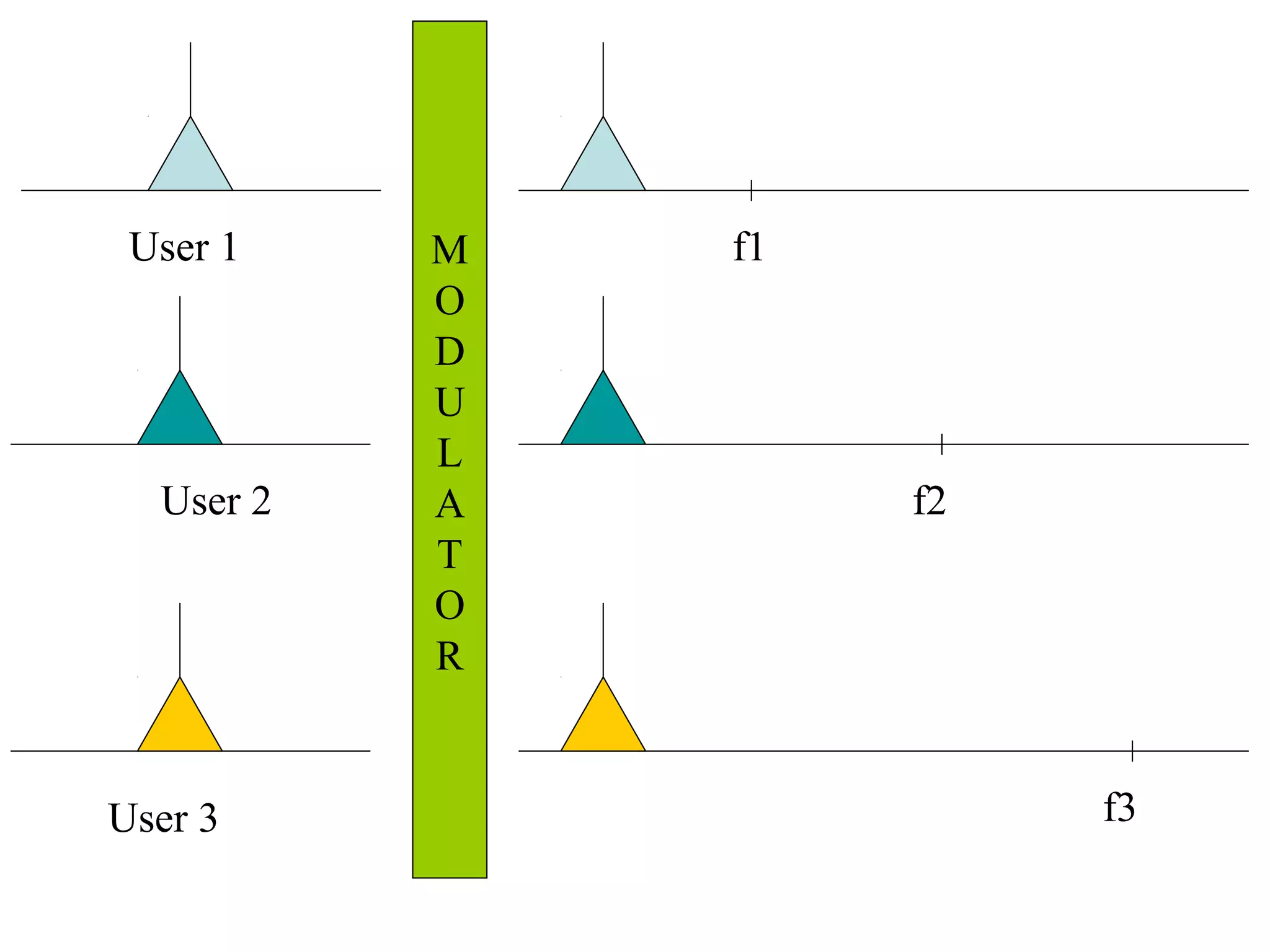
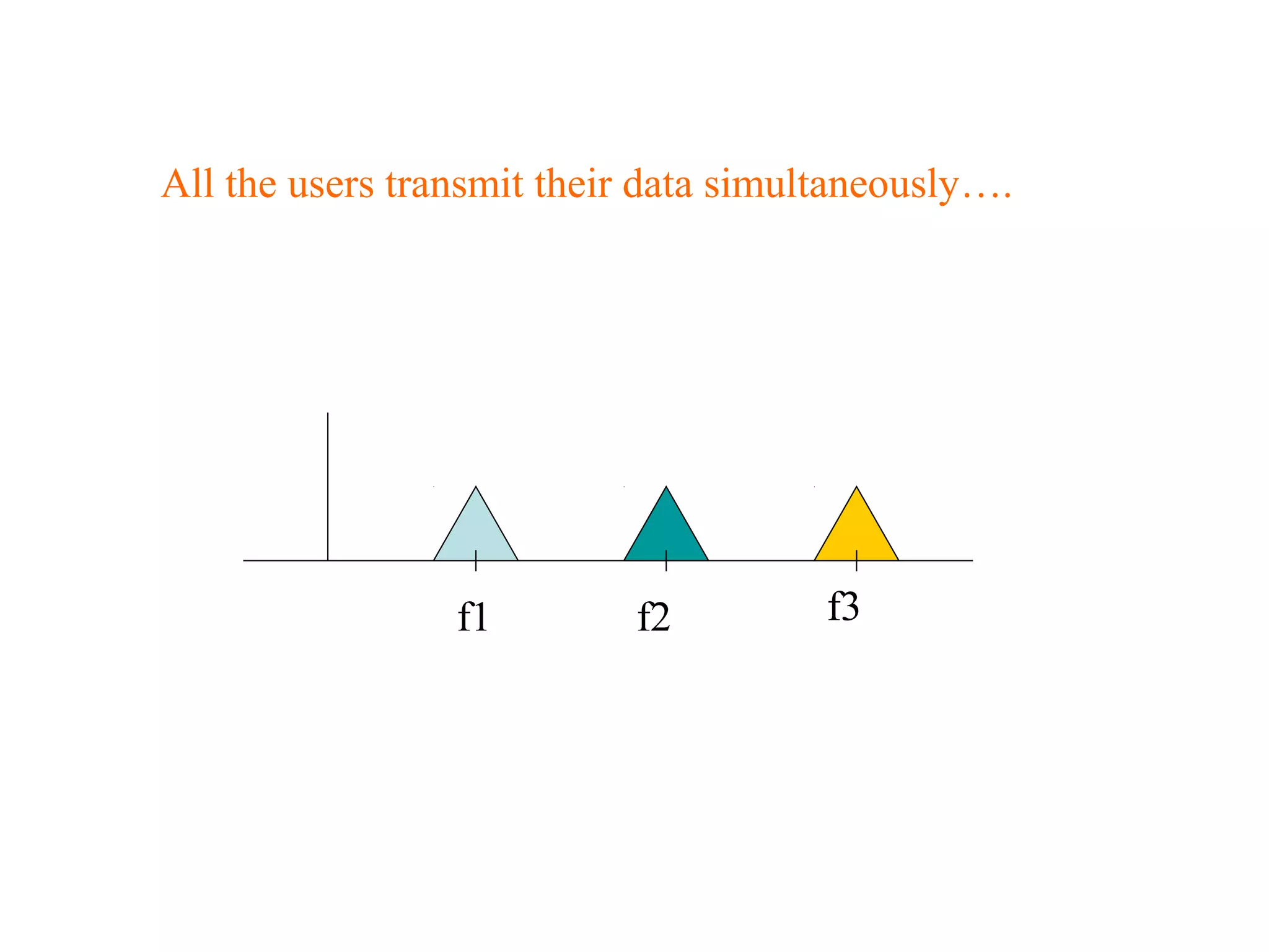
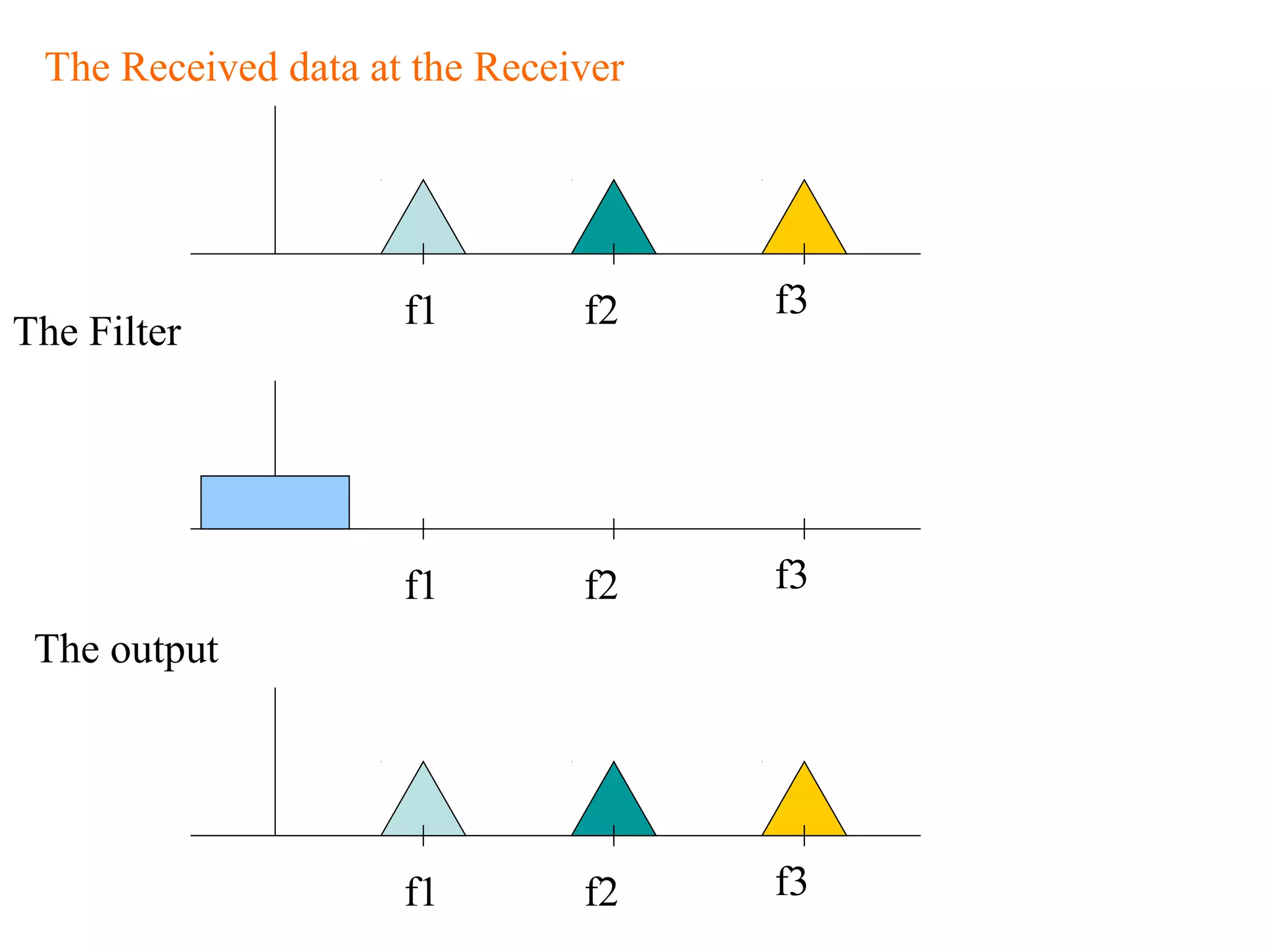
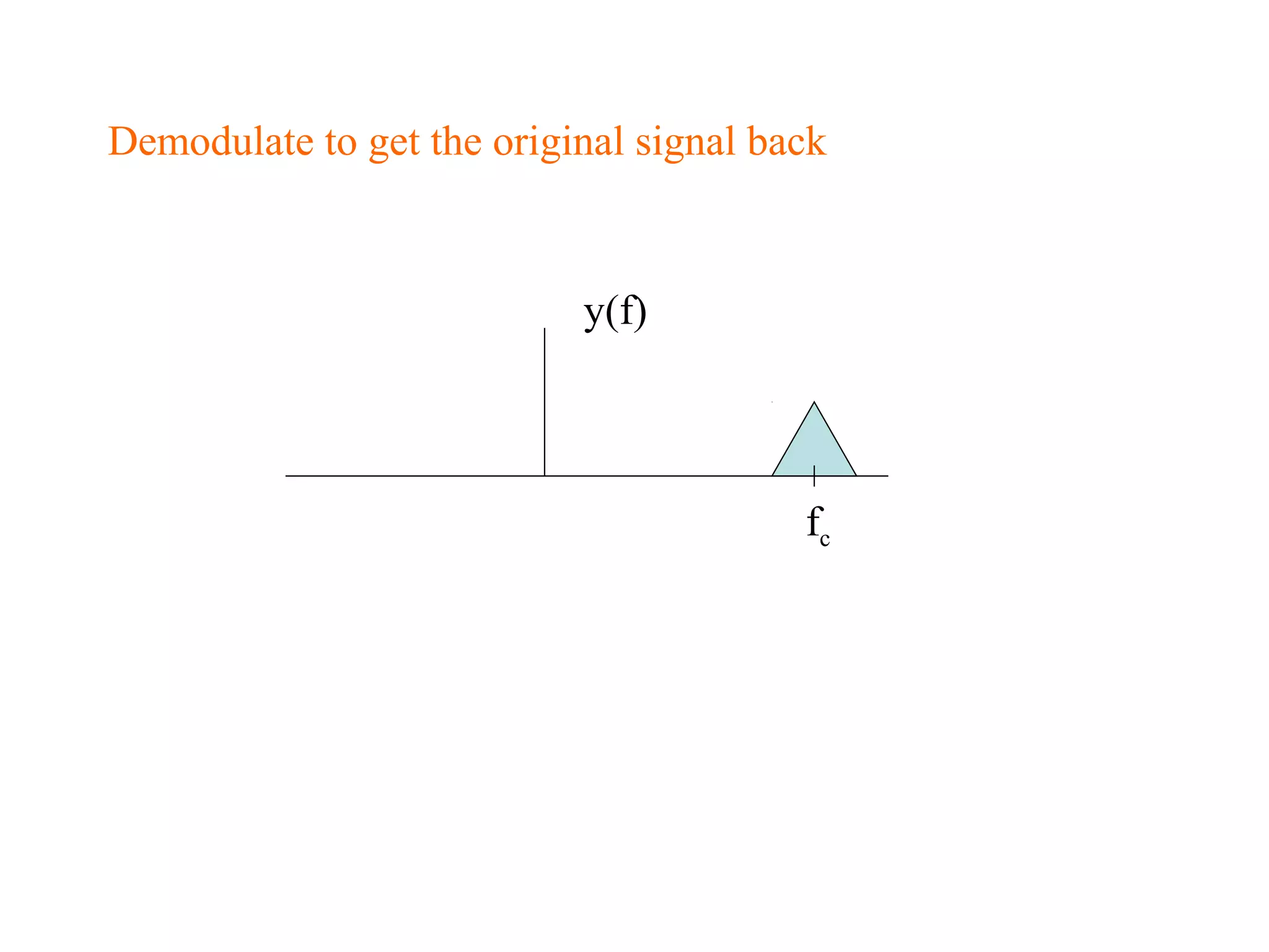
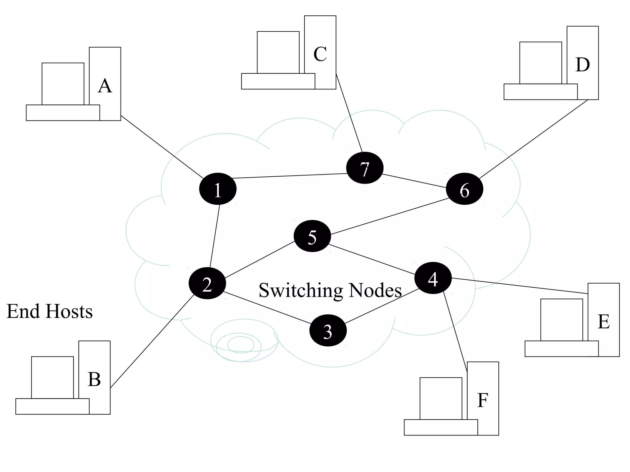
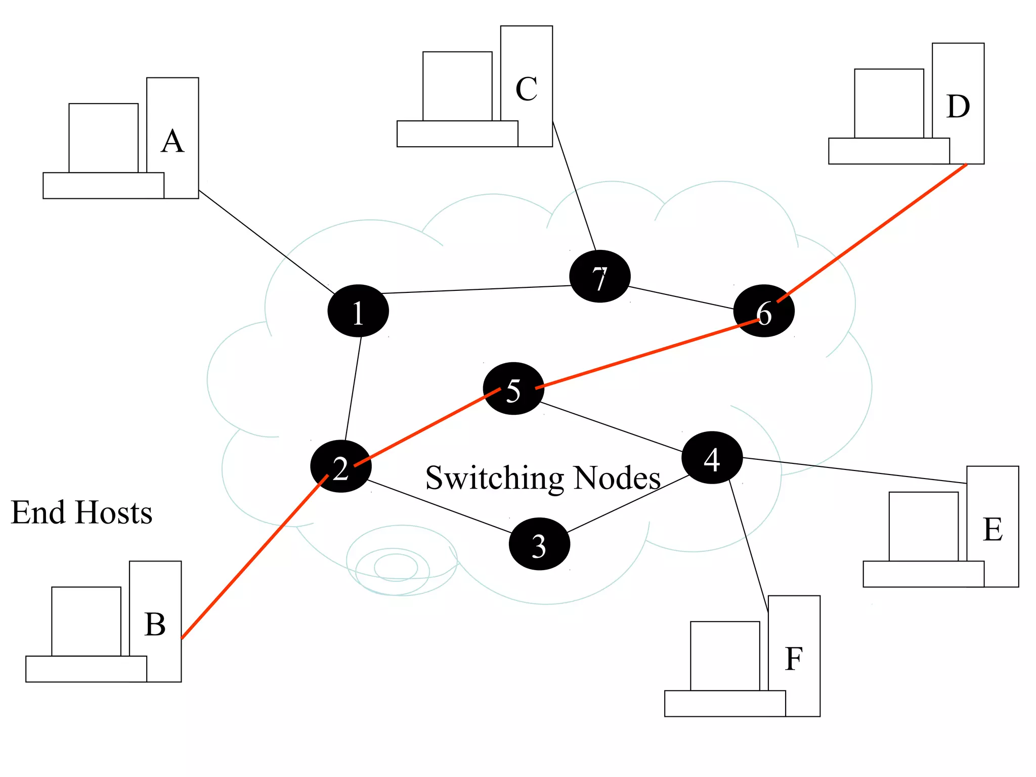
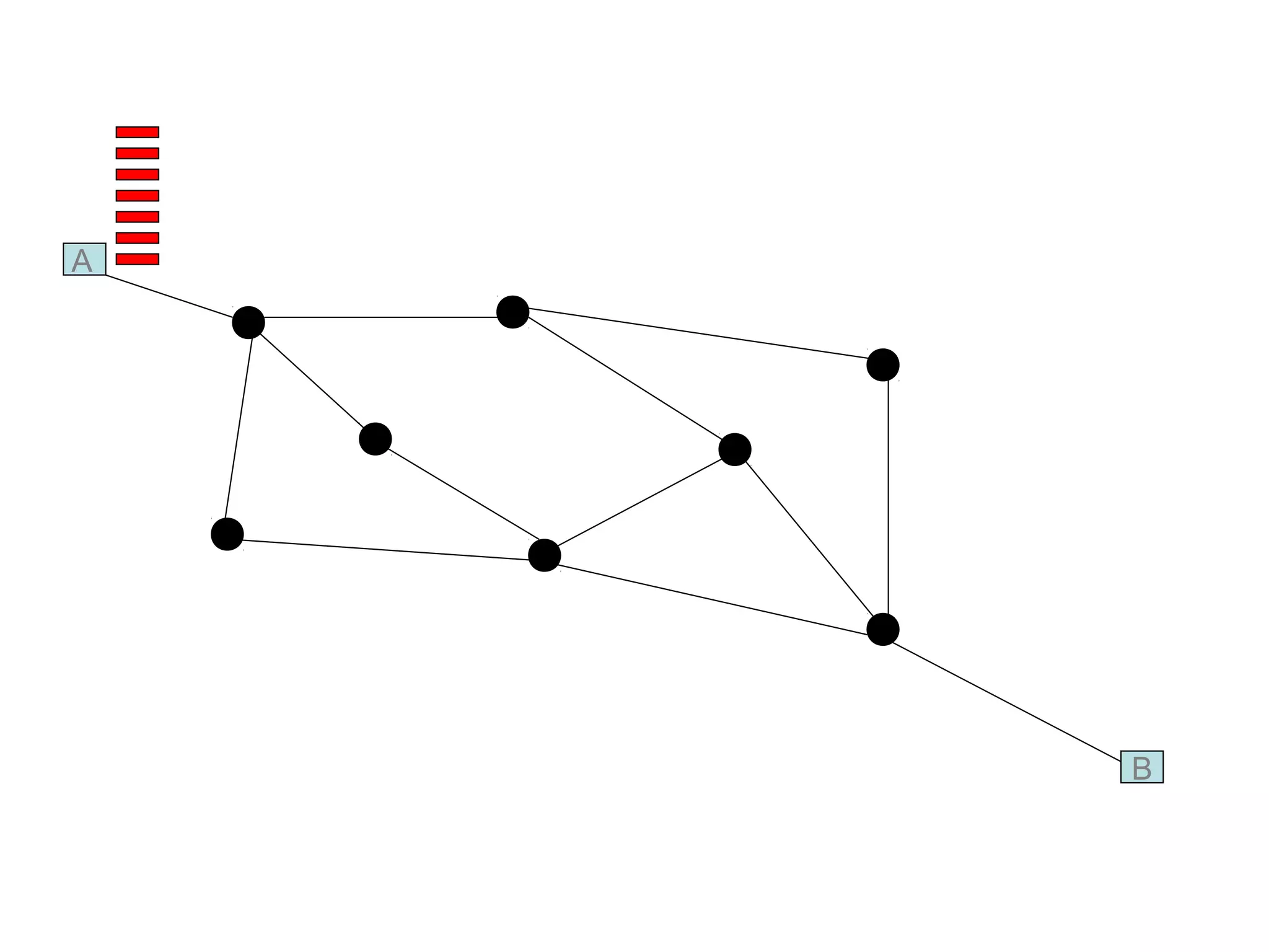
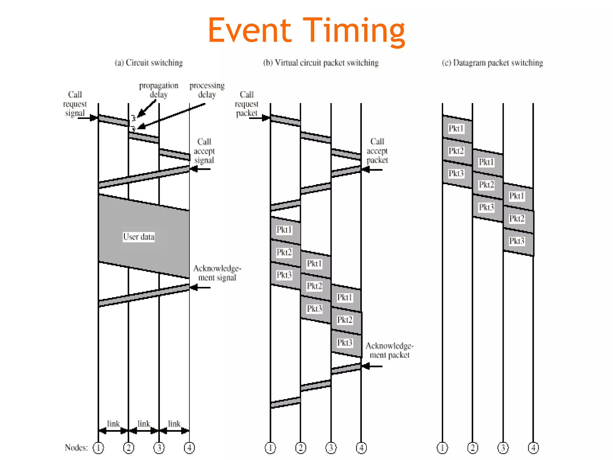

Multiplexing techniques such as time division multiplexing (TDM) and frequency division multiplexing (FDM) allow multiple users to share network links. TDM divides time into slots that are allocated to users on a fixed or dynamic basis. FDM assigns each user a unique frequency band to transmit in simultaneously. Switching networks move data packets through intermediate nodes using either circuit switching, which establishes a dedicated path, or packet switching, which breaks messages into packets that travel independently through the network.