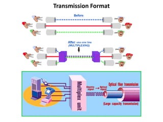
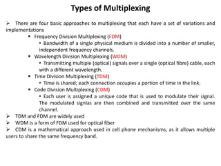
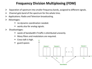
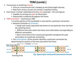
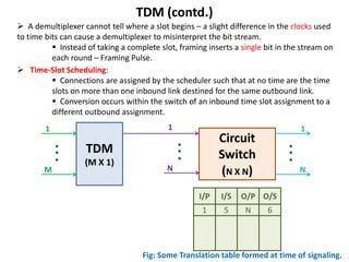
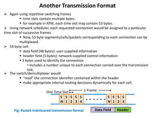
Transmission Format
 Multiplexing refers to the ‘combination’ of information streams from multiple sources
for transmission over a shared medium
 Transmitting two or more signals simultaneously can be accomplished by
setting up one transmitter-receiver pair for each channel, but this is an
expensive approach.
 Cost savings can be gained by using a single channel to send multiple
information signals over a single medium.
 Demultiplexing refers to the separation of the received signal back into separate
information streams
 Figure illustrates the basic concept:
 independent pairs of senders and receivers
• each sender communicates with a single receiver
 all pairs share a single transmission medium
 multiplexer combines information from the senders for transmission in such a
way that the demultiplexer can separate the information for receivers
Multiplexing
Types of Multiplexing
 There are four basic approaches to multiplexing that each have a set of variations and
implementations
 Frequency Division Multiplexing (FDM)
• Bandwidth of a single physical medium is divided into a number of smaller,
independent frequency channels.
 Wavelength Division Multiplexing (WDM)
• Transmitting multiple (optical) signals over a single (optical fibre) cable, each
with a different wavelength.
 Time Division Multiplexing (TDM)
• Time is shared; each connection occupies a portion of time in the link.
 Code Division Multiplexing (CDM)
• Each user is assigned a unique code that is used to modulate their signal.
The modulated signlas are then combined and transmitted over the same
channel.
 TDM and FDM are widely used
 WDM is a form of FDM used for optical fiber
 CDM is a mathematical approach used in cell phone mechanisms, as it allows multiple
users to share the same frequency band.
Frequency Division Multiplexing (FDM)
 Separation of spectrum into smaller frequency bands, assigned to different signals.
 Channel gets band of the spectrum for the whole time.
 Applications: Radio and Television broadcasting.
 Advantages:
 no dynamic coordination needed.
 works also for analog signals.
 Disadvantages:
 waste of bandwidth if traffic is distributed unevenly.
 Many filters and modulators are required.
 Cross-talk is high.
 guard spaces
Time Division Multiplexing (TDM)
Definition: Time Division Multiplexing (TDM) is the time interleaving of samples from several
sources so that the information from these sources can be transmitted serially over a single
communication channel.
At the Transmitter
 Simultaneous transmission of several signals on a time-sharing basis.
 Each signal occupies its own distinct time slot, using all frequencies, for the duration of
the transmission.
 Slots may be permanently assigned on demand.
At the Receiver
 Decommutator (sampler) has to be synchronized with the incoming waveform  Frame
Synchronization
 samples are recovered by the Low pass filter
 Feedthrough of one channel's signal into another channel -- Crosstalk
Applications of TDM: Digital Telephony, Data communications, Satellite Access,
Cellular radio.
TDM (contd.)
 Transmission or Switching Frames:
 Time on a transmission link is divided up into fixed-length intervals.
 Data from various sources are carried in repetitive frames.
 Each frame is further subdivided into time slots (example – M in the figure).
 Capable of carrying one byte of information.
 Sequentially numbered throughout the frame.
 TDM connection – synchronous TDM
 A certain portion of the bandwidth is reserved for a particular connection.
 Network Controller or Scheduler:
• Assign each newly requested connection to one particular time slot from
the switching frame.
• Different time slots within the frame carry information corresponding to
different connections.
• Return time slots to the unused pool (possible reassignment) upon
termination of a particular connection.
 The demultiplexer at the receiver identifies a particular connection by
determining the position of the time slot within the frame.
C
1
C
2
C
3
C
M
-
1
C
M
C
V
C
V
C
V
C
1
C
2
C
3
C
M
C
1
C
2
C
3
C
M
C
V
C
V
C
V
One Time Slot
1 Frame
Framing Pulse
Fig: Typical byte-interleaved transmission format
TDM (contd.)
 A demultiplexer cannot tell where a slot begins – a slight difference in the clocks used
to time bits can cause a demultiplexer to misinterpret the bit stream.
 Instead of taking a complete slot, framing inserts a single bit in the stream on
each round – Framing Pulse.
 Time-Slot Scheduling:
 Connections are assigned by the scheduler such that at no time are the time
slots on more than one inbound link destined for the same outbound link.
 Conversion occurs within the switch of an inbound time slot assignment to a
different outbound assignment.
Circuit
Switch
(N X N)
1
N
1
N
TDM
(M X 1)
1
M
I/S O/P O/S
I/P
5 N 6
1
Fig: Some Translation table formed at time of signaling.
TDM (contd.)
 Data rate of the transmission line and the data rate of each connection is determined
by the number of time slots per frame, and period of the switching frame.
 data rate for each user/connection is fixed.
 Example:
 DS1 transmission system allows 24 (1 byte) time slots = 192 bits/frame.
 8000 frames can be transmitted per second = frame length is 125 µsec.
 Each connection consists of one byte every 125 µsec = 64 kbps connection data
rate.
 Frame-mark bit (or the framing pulse) = 1bit/frame = 8 kbps signalling channel.
 Data rate of the transmission link –
• 24 time slots/frame, each slot supports 64 kbps connection = 1.536 Mbps
• signalling channel of 8 kbps
• Total Data rate of DS1 link is 1.544 Mbps.
 Disadvantage of this form of switching –
 inflexible – the user can’t transmit more than, say, 64 kbps because the slot
duration (= 8 bits) is fixed frame duration (= 125 µsec) is also fixed.
 What happens when different users have different data rates to transmit?
 Multi rate circuit switching – allocate more than 1 slot to same user!
 BUT if we have a spectrum of users with different data rates (e.g.: from 1 kbps to 1
Mbps), how to choose the basic channel rate?
 What happens if all slots are already allocated, and another user dials in?
Another Transmission Format
S
2
S
3
S
4
S
N
S
1
S
1
S
2
S
3
S
N
One Time Slot 1 Frame
Fig: Packet-interleaved transmission format
C
V
C
V
C
V
C
V
C
V
C
V
Data Field Header
 Again using repetitive switching frames
 time slots contain multiple bytes.
 for example in ATM, each time slot may contain 53 bytes.
 Using network scheduler, each requested connection would be assigned to a particular
time slot of successive frames.
 Now, 53 byte segments/cells/packets corresponding to each connection can be
multiplexed.
 53-byte cell:
 data field (48 bytes): user-supplied information
 header field (5 bytes): network-supplied control information
 3 bytes used to identify the connection
• includes a number unique to each connection carried over the transmission
link.
 The switch/demultiplexer would
 “read” the connection identifier contained within the header
 make appropriate internal routing decisions dynamically for each cell.
Packet Switching
 No need for a synchronous time-multiplexed frame!
 Use Statistical Multiplexing!
 In this scheme:
 Transmission time slots occur regularly but may not have any framing structure.
 Time slots are not allocated to any connection.
• No particular admission control.
• Payloads/cells/packets associated with a particular connection may occur
asynchronously!
 All users are allowed to transmit – if the combined data rate of all the users
 exceed the output capacity, bits would have to be either dropped or
queued/buffered.
 is less than the output capacity, no queuing.
Stat Mux
(buffer)
(K X 1)
1
K
 The terminating switch must contain smoothing buffers to temporarily store cells that
arrive on 2 or more inbound transmission links destined for the same outbound link
simultaneously.
 A ‘scheduler’ will schedule these packets on to the output link.
 Only one cell can be present on any outbound link at any given time.
 Such competing cells are sequentially read onto the time slots of the outbound
links.
Switching
Packet Switching (contd.)
 Circuit switching – Blocking
 If all slots are occupied, new connection is blocked.
 performance characteristic – probability of call blocking.
• The only delays are the switching latencies that occur in space division
switching
 suitable for real time services
 Statistical Multiplexing – Queuing
 no concept of admission control.
 performance characteristic – queuing delay.
 suitable for bursty traffic.
• ratio of peak rate to average rate is very large for bursty traffic;
permanent allocation leads to under-utilization of the channel.
• these bursty sources must be capable of tolerating some delays.
 Packet Switch network is ‘a best effort’ network.
 network will make every attempt to transmit the packet
 but offers no quality of service guarantees, in terms of delays.
 In any practical statistical multiplexer, the buffer size is finite/limited.
 In case buffer gets full, anymore incoming packet gets dropped.
 Real time services require some guarantee on delays and/or packet loss.

Introduction to multiplexing, packet switching.pptx

  • 1.
  • 2.
     Multiplexing refersto the ‘combination’ of information streams from multiple sources for transmission over a shared medium  Transmitting two or more signals simultaneously can be accomplished by setting up one transmitter-receiver pair for each channel, but this is an expensive approach.  Cost savings can be gained by using a single channel to send multiple information signals over a single medium.  Demultiplexing refers to the separation of the received signal back into separate information streams  Figure illustrates the basic concept:  independent pairs of senders and receivers • each sender communicates with a single receiver  all pairs share a single transmission medium  multiplexer combines information from the senders for transmission in such a way that the demultiplexer can separate the information for receivers Multiplexing
  • 3.
    Types of Multiplexing There are four basic approaches to multiplexing that each have a set of variations and implementations  Frequency Division Multiplexing (FDM) • Bandwidth of a single physical medium is divided into a number of smaller, independent frequency channels.  Wavelength Division Multiplexing (WDM) • Transmitting multiple (optical) signals over a single (optical fibre) cable, each with a different wavelength.  Time Division Multiplexing (TDM) • Time is shared; each connection occupies a portion of time in the link.  Code Division Multiplexing (CDM) • Each user is assigned a unique code that is used to modulate their signal. The modulated signlas are then combined and transmitted over the same channel.  TDM and FDM are widely used  WDM is a form of FDM used for optical fiber  CDM is a mathematical approach used in cell phone mechanisms, as it allows multiple users to share the same frequency band.
  • 4.
    Frequency Division Multiplexing(FDM)  Separation of spectrum into smaller frequency bands, assigned to different signals.  Channel gets band of the spectrum for the whole time.  Applications: Radio and Television broadcasting.  Advantages:  no dynamic coordination needed.  works also for analog signals.  Disadvantages:  waste of bandwidth if traffic is distributed unevenly.  Many filters and modulators are required.  Cross-talk is high.  guard spaces
  • 5.
    Time Division Multiplexing(TDM) Definition: Time Division Multiplexing (TDM) is the time interleaving of samples from several sources so that the information from these sources can be transmitted serially over a single communication channel. At the Transmitter  Simultaneous transmission of several signals on a time-sharing basis.  Each signal occupies its own distinct time slot, using all frequencies, for the duration of the transmission.  Slots may be permanently assigned on demand. At the Receiver  Decommutator (sampler) has to be synchronized with the incoming waveform  Frame Synchronization  samples are recovered by the Low pass filter  Feedthrough of one channel's signal into another channel -- Crosstalk Applications of TDM: Digital Telephony, Data communications, Satellite Access, Cellular radio.
  • 6.
    TDM (contd.)  Transmissionor Switching Frames:  Time on a transmission link is divided up into fixed-length intervals.  Data from various sources are carried in repetitive frames.  Each frame is further subdivided into time slots (example – M in the figure).  Capable of carrying one byte of information.  Sequentially numbered throughout the frame.  TDM connection – synchronous TDM  A certain portion of the bandwidth is reserved for a particular connection.  Network Controller or Scheduler: • Assign each newly requested connection to one particular time slot from the switching frame. • Different time slots within the frame carry information corresponding to different connections. • Return time slots to the unused pool (possible reassignment) upon termination of a particular connection.  The demultiplexer at the receiver identifies a particular connection by determining the position of the time slot within the frame. C 1 C 2 C 3 C M - 1 C M C V C V C V C 1 C 2 C 3 C M C 1 C 2 C 3 C M C V C V C V One Time Slot 1 Frame Framing Pulse Fig: Typical byte-interleaved transmission format
  • 7.
    TDM (contd.)  Ademultiplexer cannot tell where a slot begins – a slight difference in the clocks used to time bits can cause a demultiplexer to misinterpret the bit stream.  Instead of taking a complete slot, framing inserts a single bit in the stream on each round – Framing Pulse.  Time-Slot Scheduling:  Connections are assigned by the scheduler such that at no time are the time slots on more than one inbound link destined for the same outbound link.  Conversion occurs within the switch of an inbound time slot assignment to a different outbound assignment. Circuit Switch (N X N) 1 N 1 N TDM (M X 1) 1 M I/S O/P O/S I/P 5 N 6 1 Fig: Some Translation table formed at time of signaling.
  • 8.
    TDM (contd.)  Datarate of the transmission line and the data rate of each connection is determined by the number of time slots per frame, and period of the switching frame.  data rate for each user/connection is fixed.  Example:  DS1 transmission system allows 24 (1 byte) time slots = 192 bits/frame.  8000 frames can be transmitted per second = frame length is 125 µsec.  Each connection consists of one byte every 125 µsec = 64 kbps connection data rate.  Frame-mark bit (or the framing pulse) = 1bit/frame = 8 kbps signalling channel.  Data rate of the transmission link – • 24 time slots/frame, each slot supports 64 kbps connection = 1.536 Mbps • signalling channel of 8 kbps • Total Data rate of DS1 link is 1.544 Mbps.  Disadvantage of this form of switching –  inflexible – the user can’t transmit more than, say, 64 kbps because the slot duration (= 8 bits) is fixed frame duration (= 125 µsec) is also fixed.  What happens when different users have different data rates to transmit?  Multi rate circuit switching – allocate more than 1 slot to same user!  BUT if we have a spectrum of users with different data rates (e.g.: from 1 kbps to 1 Mbps), how to choose the basic channel rate?  What happens if all slots are already allocated, and another user dials in?
  • 9.
    Another Transmission Format S 2 S 3 S 4 S N S 1 S 1 S 2 S 3 S N OneTime Slot 1 Frame Fig: Packet-interleaved transmission format C V C V C V C V C V C V Data Field Header  Again using repetitive switching frames  time slots contain multiple bytes.  for example in ATM, each time slot may contain 53 bytes.  Using network scheduler, each requested connection would be assigned to a particular time slot of successive frames.  Now, 53 byte segments/cells/packets corresponding to each connection can be multiplexed.  53-byte cell:  data field (48 bytes): user-supplied information  header field (5 bytes): network-supplied control information  3 bytes used to identify the connection • includes a number unique to each connection carried over the transmission link.  The switch/demultiplexer would  “read” the connection identifier contained within the header  make appropriate internal routing decisions dynamically for each cell.
  • 10.
    Packet Switching  Noneed for a synchronous time-multiplexed frame!  Use Statistical Multiplexing!  In this scheme:  Transmission time slots occur regularly but may not have any framing structure.  Time slots are not allocated to any connection. • No particular admission control. • Payloads/cells/packets associated with a particular connection may occur asynchronously!  All users are allowed to transmit – if the combined data rate of all the users  exceed the output capacity, bits would have to be either dropped or queued/buffered.  is less than the output capacity, no queuing. Stat Mux (buffer) (K X 1) 1 K  The terminating switch must contain smoothing buffers to temporarily store cells that arrive on 2 or more inbound transmission links destined for the same outbound link simultaneously.  A ‘scheduler’ will schedule these packets on to the output link.  Only one cell can be present on any outbound link at any given time.  Such competing cells are sequentially read onto the time slots of the outbound links.
  • 11.
  • 12.
    Packet Switching (contd.) Circuit switching – Blocking  If all slots are occupied, new connection is blocked.  performance characteristic – probability of call blocking. • The only delays are the switching latencies that occur in space division switching  suitable for real time services  Statistical Multiplexing – Queuing  no concept of admission control.  performance characteristic – queuing delay.  suitable for bursty traffic. • ratio of peak rate to average rate is very large for bursty traffic; permanent allocation leads to under-utilization of the channel. • these bursty sources must be capable of tolerating some delays.  Packet Switch network is ‘a best effort’ network.  network will make every attempt to transmit the packet  but offers no quality of service guarantees, in terms of delays.  In any practical statistical multiplexer, the buffer size is finite/limited.  In case buffer gets full, anymore incoming packet gets dropped.  Real time services require some guarantee on delays and/or packet loss.

Editor's Notes

  • #2 Dedicated lines – top ; shared line – middle; how is it done? Via multiplexing!
  • #5 Application – AM & FM Radio!! Guard spaces also take up the bandwidth – waste of link capacity
  • #6 Interleave – insert/ mix by alternating between many signals.
  • #7  TDM Connection – Synchronous – time slot assigned to a particular connection occur regularly, in the same position of successive frames. So, if user 1 or channel 1 transmits data in slot 2, the next time he can transmit data is in slot 2 of the next frame and so on…So, in 1 frame, 1 user is allowed to transmit only 1 byte or 8 bits. Information is broken down into byte-size units, carried recurring in the assigned time slot on successive frame.
  • #8 Time Slot Scheduling -> 1) Same outgoing link par 1 se jyada incoming links same time slot par nahin dalenge. 2) Aur agar 1 se jyada time slots pe data aa raha for the same outgoing link, conversion kar dete hain to different outgoing link. Traditionally, the oldest transfer mode used in telecommunication switching is circuit switching, which uses the principle of TDM. In this example figure, output of the TDM is one of the input of the circuit switch. Say, M users have been multiplexed into port 1 of the switch – so, here, the frame coming into port 1 is divided into M slots. So, the bits of some slot in TDM have to be switched to some particular o/p slot of ckt s/w. The circuit switch will have some sort of switch table – i/p port, i/p slot, o/p port, o/p slot. Example – slot 5 (in each frame) of Input port 1 may have to be switched to slot 6 (again of each frame) of output port N. This kind of table is built at the time of signaling.
  • #9  DS1 – Digital Signal 1 – primary digital phone standard Each connection – 1 time slot/frame – 1 byte/ usec = 64kbps Trans. Link – Data rate: 192 bits/frame, 8000 frames/sec -> 1.536 Mbps As we learnt previously, in circuit switching, as long as the connection is established, there are no delays/latencys allowed, so ckt s/wing is suitable for real time services like voice or video. Multi rate ckt s/wing – in the example above, we have chosen a basic channel rate of 64 kbps. To accommodate a user with data rate of 128 kbps, we give him 2 slots in that frame of 125 usec duration. What about 16 kbps!? – only 1 slot in every 4 frames will be occupied, and the remaining 3 frames will remain unutilized because the basic channel rate is 64 kbps. What is you chose the basic channel rate to be the lowest allowable rate? Say, 16 kbps? Then to transmit 128 kbps, we have to have large number of slots per frame, which makes the hardware and slot synchronization complex. What if another user dials in? He’ll get a busy tone, because we have no free slot.
  • #10 Asynchronous Transfer Mode: 3 bytes – rather than a single byte previously. Each segment/cell is divided in 2 field: data/header Because the time slot is large enough to carry the information used to identify a given connection, synchronoud tdm/network scheduler – not needed.
  • #11 53 bytes – rather than a single byte previously. Each segment/cell is divided in 2 field: data/header Because the time slot is large enough to carry the information used to identify a given connection, synchronous tdm/network scheduler – not needed. Cells corresponding to a given connection are randomly interdispersed with the cells corresponding to other connections. – asynchronous. Unlike TDM, where no. of slots and thus, no. of users are fixed, stat mux allows all users to transmit. If output capacity is exceeded, some bits would have to be either dropped or queued/buffered – each user transmits his bits in a particular format – packets; and these packets get queued in the buffer Scheduler picks these packets one by one and puts it onto the o/p link.
  • #12 The transmission formats for circuit switching & packet switching can be seen here Also, we get an idea of space-division in switching.
  • #13 Circuit s/wing was characterized by blocking. – if all M slots are occupied, when the M+1th user attempts to transmit, he’ll get a busy tone or he gets blocked. Only delay is due to space division switching – delays while establishing connections Stat mux – all users are allowed to transmit, and their packets will sit in a buffer – because there is no limit on allowable number of users, this queuing delay can be very large.