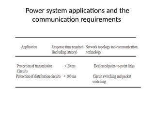
Introduction
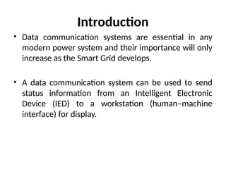
• Data communicationsystems are essential in any
modern power system and their importance will only
increase as the Smart Grid develops.
• A data communication system can be used to send
status information from an Intelligent Electronic
Device (IED) to a workstation (human–machine
interface) for display.
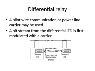
Differential relay
• Apilot wire communication or power line
carrier may be used.
• A bit stream from the differential IED is first
modulated with a carrier.
8.
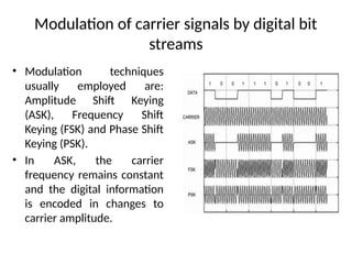
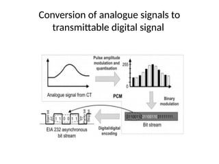
Modulation of carriersignals by digital bit
streams
• Modulation techniques
usually employed are:
Amplitude Shift Keying
(ASK), Frequency Shift
Keying (FSK) and Phase Shift
Keying (PSK).
• In ASK, the carrier
frequency remains constant
and the digital information
is encoded in changes to
carrier amplitude.
9.
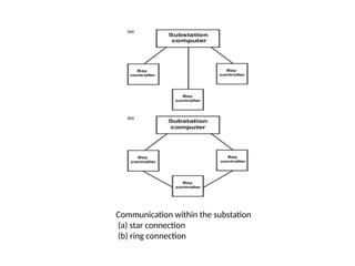
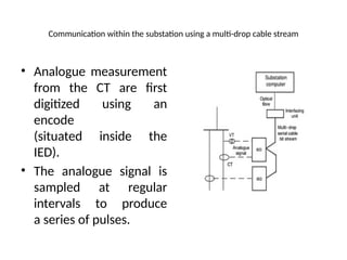
Communication within thesubstation using a multi-drop cable stream
• Analogue measurement
from the CT are first
digitized using an
encode
(situated inside the
IED).
• The analogue signal is
sampled at regular
intervals to produce
a series of pulses.
Circuit switching
• Incircuit switching, a dedicated physical connection
is set up for the exclusive use of Source and
Destination during the communication session.
• Nodes and links allocated for a communication
session cannot be used by any Source/Destination
other than the two involved in the communication
session.
12.
Message switching
• Inmessage switching, the Source sends a message to
a node.
• A message could be measurement data collected by
a sensor or a control function.
• The node stores the data in its buffer.
• When the entire message has been delivered to the
node, it then looks for a free link to another node and
then sends the data to this node.
• This process continues until the data is delivered to
the Destination. Owing to its working principle, it is
also known as store and forward.
13.
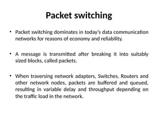
Packet switching
• Packetswitching dominates in today’s data communication
networks for reasons of economy and reliability.
• A message is transmitted after breaking it into suitably
sized blocks, called packets.
• When traversing network adapters, Switches, Routers and
other network nodes, packets are buffered and queued,
resulting in variable delay and throughput depending on
the traffic load in the network.
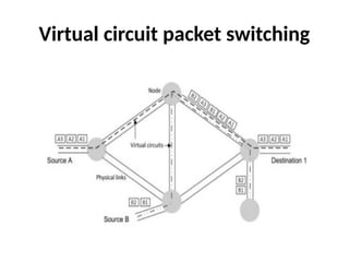
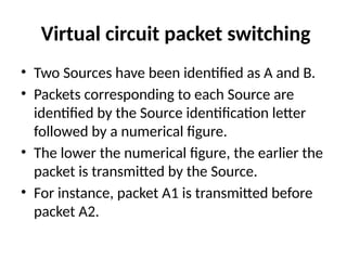
Virtual circuit packetswitching
• Two Sources have been identified as A and B.
• Packets corresponding to each Source are
identified by the Source identification letter
followed by a numerical figure.
• The lower the numerical figure, the earlier the
packet is transmitted by the Source.
• For instance, packet A1 is transmitted before
packet A2.
16.
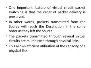
• One importantfeature of virtual circuit packet
switching is that the order of packet delivery is
preserved.
• In other words, packets transmitted from the
Source will reach the Destination in the same
order as they left the Source.
• The packets transmitted through several virtual
circuits are multiplexed through physical links.
• This allows efficient utilization of the capacity of a
physical link.
17.
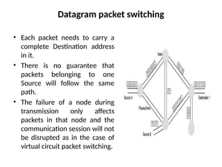
Datagram packet switching
•Each packet needs to carry a
complete Destination address
in it.
• There is no guarantee that
packets belonging to one
Source will follow the same
path.
• The failure of a node during
transmission only affects
packets in that node and the
communication session will not
be disrupted as in the case of
virtual circuit packet switching.
18.
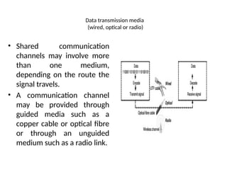
Data transmission media
(wired,optical or radio)
• Shared communication
channels may involve more
than one medium,
depending on the route the
signal travels.
• A communication channel
may be provided through
guided media such as a
copper cable or optical fibre
or through an unguided
medium such as a radio link.
19.
Bandwidth/Bit rate
• Bandwidthis the difference between the upper and
lower cut-off frequencies of a communication
channel.
• In an analogue system it is typically measured in
Hertz.
• In digital transmission the term bit rate is often used
to express the capacity (some
books refer to as bandwidth) of a channel.
• The bit rate is measured in bits per second (bps).
20.
Attenuation
• As asignal propagates along a communication
channel, its amplitude decreases.
• In long-distance transmission, amplifiers (for
analogue signals) and repeaters (for
digital signals) are installed at regular intervals
to boost attenuated signals.
21.
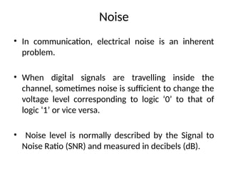
Noise
• In communication,electrical noise is an inherent
problem.
• When digital signals are travelling inside the
channel, sometimes noise is sufficient to change the
voltage level corresponding to logic ‘0’ to that of
logic ‘1’ or vice versa.
• Noise level is normally described by the Signal to
Noise Ratio (SNR) and measured in decibels (dB).
22.
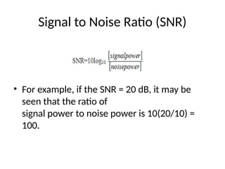
Signal to NoiseRatio (SNR)
• For example, if the SNR = 20 dB, it may be
seen that the ratio of
signal power to noise power is 10(20/10) =
100.
23.
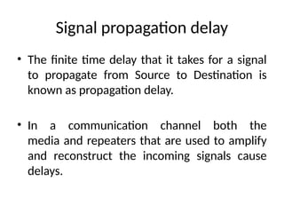
Signal propagation delay
•The finite time delay that it takes for a signal
to propagate from Source to Destination is
known as propagation delay.
• In a communication channel both the
media and repeaters that are used to amplify
and reconstruct the incoming signals cause
delays.
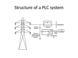
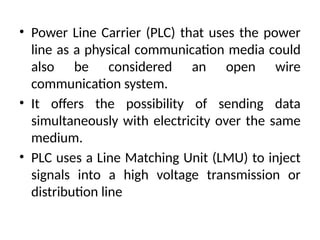
• Power LineCarrier (PLC) that uses the power
line as a physical communication media could
also be considered an open wire
communication system.
• It offers the possibility of sending data
simultaneously with electricity over the same
medium.
• PLC uses a Line Matching Unit (LMU) to inject
signals into a high voltage transmission or
distribution line
27.
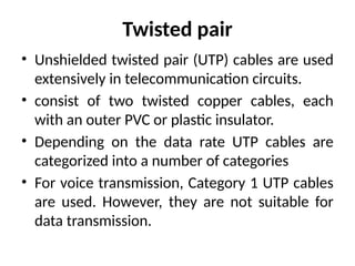
Twisted pair
• Unshieldedtwisted pair (UTP) cables are used
extensively in telecommunication circuits.
• consist of two twisted copper cables, each
with an outer PVC or plastic insulator.
• Depending on the data rate UTP cables are
categorized into a number of categories
• For voice transmission, Category 1 UTP cables
are used. However, they are not suitable for
data transmission.
28.
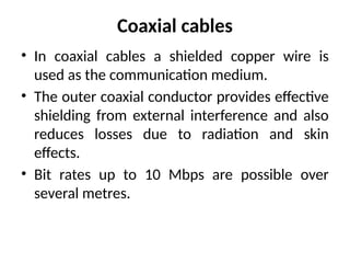
Coaxial cables
• Incoaxial cables a shielded copper wire is
used as the communication medium.
• The outer coaxial conductor provides effective
shielding from external interference and also
reduces losses due to radiation and skin
effects.
• Bit rates up to 10 Mbps are possible over
several metres.
29.
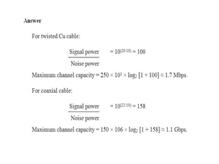
• Example:
According toShannon’s capacity formula, the
maximum channel capacity in bps is given by B
log2[1 + (signal power) / (noise power)], where
B is the bandwidth of a
channel in Hz. Compare the maximum channel
capacity of twisted copper and coaxial
cables. For copper cable, the bandwidth is 250
kHz and the SNR is 20 dB. For coaxial
cable, the bandwidth is 150 MHz and the SNR
is 22 dB.
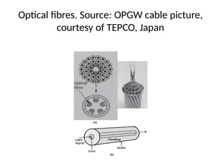
Optical Ground Wires(OPGW).
• Optical fibre transmission is used both inside
substations and for long-distance transmission
of data.
• Optical fibres are often embedded in the
stranded conductors of the shield (ground)
wires of overhead lines.
• These cables are known as Optical Ground
Wires (OPGW).
33.
Disadvantage
• The maindisadvantages of optical fibre
transmission include the cost, the special
termination requirements and its vulnerability
(it is more fragile than coaxial cable).
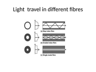
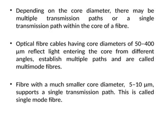
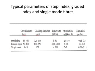
• Depending onthe core diameter, there may be
multiple transmission paths or a single
transmission path within the core of a fibre.
• Optical fibre cables having core diameters of 50–400
μm reflect light entering the core from different
angles, establish multiple paths and are called
multimode fibres.
• Fibre with a much smaller core diameter, 5–10 μm,
supports a single transmission path. This is called
single mode fibre.
39.
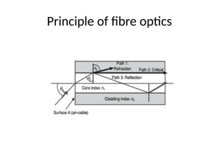
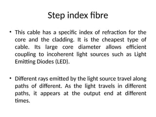
Step index fibre
•This cable has a specific index of refraction for the
core and the cladding. It is the cheapest type of
cable. Its large core diameter allows efficient
coupling to incoherent light sources such as Light
Emitting Diodes (LED).
• Different rays emitted by the light source travel along
paths of different. As the light travels in different
paths, it appears at the output end at different
times.
40.
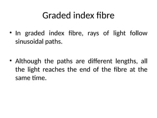
Graded index fibre
•In graded index fibre, rays of light follow
sinusoidal paths.
• Although the paths are different lengths, all
the light reaches the end of the fibre at the
same time.
Example
• A step-indexmultimode fibre has a core of
refractive index 1.5 and cladding of refractive
index 1.485.
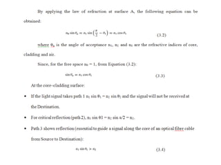
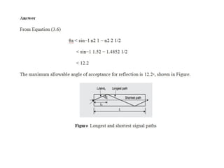
1. What is the maximum allowable angle of
acceptance for refraction on core–cladding
surface?
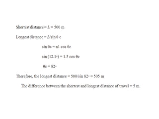
2. If the length of the fibre is 500 m, what is
the difference of distance of travel between
the longest and shortest signal path?
45.
Radio communication
• Thesubstations of power networks are often widely
distributed and far from the control centre. For such long
distances, the use of copper wire or fibre optics is costly.
• Radio links provide an alternative for communication
between the Control Centre and substations.
• Radio communication may be multipoint or point-to-point,
operating typically either at UHF frequencies (between 300
MHz and 3 GHz) or microwave frequencies (between 3 and
30 GHz).
46.
Ultra high frequency
•UHF radio represents an attractive choice for applications
where the required bandwidth is relatively low and where the
communication end-points are widespread over harsh terrain.
• It uses frequencies between 300 MHz and 3 GHz.
• Unlike microwave radio, UHF does not require a line of sight
between the Source and Destination.
• The maximum distance between the Source and Destination
depends on the size of the antennae and is likely to be about
10–30 km with a bandwidth up to 192 kbps.
47.
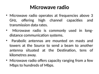
Microwave radio
• Microwaveradio operates at frequencies above 3
GHz, offering high channel capacities and
transmission data rates.
• Microwave radio is commonly used in long-
distance communication systems.
• Parabolic antennas are mounted on masts and
towers at the Source to send a beam to another
antenna situated at the Destination, tens of
kilometres away.
• Microwave radio offers capacity ranging from a few
Mbps to hundreds of Mbps.
48.
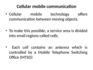
Cellular mobile communication
•Cellular mobile technology offers
communication between moving objects.
• To make this possible, a service area is divided
into small regions called cells.
• Each cell contains an antenna which is
controlled by a Mobile Telephone Switching
Office (MTSO)
49.
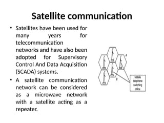
Satellite communication
• Satelliteshave been used for
many years for
telecommunication
networks and have also been
adopted for Supervisory
Control And Data Acquisition
(SCADA) systems.
• A satellite communication
network can be considered
as a microwave network
with a satellite acting as a
repeater.
50.
Geostationary orbit satellitecommunication
• Currently, many satellites that are in operation are
placed in Geostationary Orbit (GEO).
• A GEO satellite or GEOS is typically at 35,786 km
above the equator and its revolution around the Earth
is synchronized with the Earth’s rotation.
• The high altitude of a GEO satellite allows
communications from it to cover approximately one-
third of the Earth’s surface.
51.
Drawbacks
• The challengeof transmitting and detecting
the signal over the long distance between the
satellite and the user.
• The large distance travelled by the signal from
the Source to reach the Destination results in
an end-to-end delay or propagation delay of
about 250 ms.
52.
Low earth orbiting(LEO) satellite
communication
• LEO satellites are positioned 200–3000 km above the
Earth, which reduces the propagation delay
considerably.
• In addition, LEO satellite-based communication
channels can support protocols such as TCP/IP since
they support packet-oriented communication with
relatively low latency.
53.
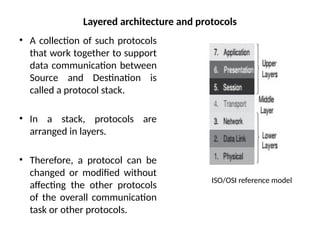
Layered architecture andprotocols
• A collection of such protocols
that work together to support
data communication between
Source and Destination is
called a protocol stack.
• In a stack, protocols are
arranged in layers.
• Therefore, a protocol can be
changed or modified without
affecting the other protocols
of the overall communication
task or other protocols.
ISO/OSI reference model
54.
The ISO/OSI model
•The ‘Open System Interconnection model’ developed
by the International Standard Organization (ISO/OSI)
is a protocol architecture which consists of seven
layers that describes the tasks associated with
moving information from Source to Destination
through a communication network.
• The Physicallayer is responsible for
transmitting data (in the form of bits) from
one node to the next as a signal over a
transmission channel.
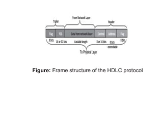
• The Data Link layer prepares data blocks
usually referred to as frames for transmission,
takes care of the synchronisation of data
transmission at both Source and Destination,
and resolves issues related to accessing the
medium shared by multiple users.
57.
• The networklayer is responsible for the delivery of
data packets from the Source to Destination across
the communication network.
• The Transport layer accepts data from the Session
layer and segments the data for transport across the
network.
• The Session layer establishes, manages, and
terminates communication sessions. Communication
sessions consist of service requests and service
responses that occur between Applications located in
different network devices.
58.
• The Presentationlayer provides a variety of coding
and conversion functions that are applied to
Application layer data.
• The Application layer is the OSI layer closest to the
end user, which means that both the OSI Application
layer and the user interact directly with the
Application.
59.
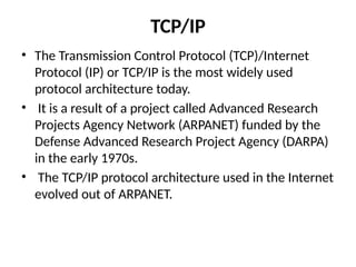
TCP/IP
• The TransmissionControl Protocol (TCP)/Internet
Protocol (IP) or TCP/IP is the most widely used
protocol architecture today.
• It is a result of a project called Advanced Research
Projects Agency Network (ARPANET) funded by the
Defense Advanced Research Project Agency (DARPA)
in the early 1970s.
• The TCP/IP protocol architecture used in the Internet
evolved out of ARPANET.
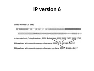
IP version 6also known as IP Next Generation (IPng) is a 128-bit
addressing scheme. Therefore, it provides a much bigger address
space compared to that of IPv4.
The main advantages provided by IPv6 include:
1. Internet Protocol Security (IPsec) is mandatory for IPv6. It is a
protocol suite for securing
Internet Protocol (IP) communications by authenticating and
encrypting each IP packet of
a communication session.
2. Support for jumbograms which can be as large as 4, 294, 967,
295 (232 − 1) octets. In
contrast, IPv4 supports datagrams up to 65, 535 (216 – 1) octets.

![• Example:
According to Shannon’s capacity formula, the
maximum channel capacity in bps is given by B
log2[1 + (signal power) / (noise power)], where
B is the bandwidth of a
channel in Hz. Compare the maximum channel
capacity of twisted copper and coaxial
cables. For copper cable, the bandwidth is 250
kHz and the SNR is 20 dB. For coaxial
cable, the bandwidth is 150 MHz and the SNR
is 22 dB.](https://image.slidesharecdn.com/chap-5-250311021114-3bc59618/85/CHAP-5EngineeringsmartgridmaterialBEstudy-pptx-29-320.jpg)


![Chapter-2 Communiction media [Autosaved].ppt](https://cdn.slidesharecdn.com/ss_thumbnails/chapter-2communictionmediaautosaved-260117143116-9787c933-thumbnail.jpg?width=640&height=640&fit=bounds)


