Download as PDF, PPTX


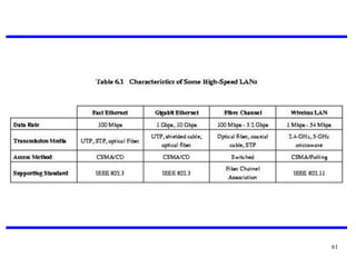


This document provides an overview of high speed networks including Frame Relay networks, Asynchronous Transfer Mode (ATM), ATM protocol architecture, logical connections, cells, service categories, and high speed LANs. It discusses the architecture, user data transfer, and call control of Frame Relay networks. For ATM, it describes the protocol model, logical connections, cells, adaptation layer, and service categories. It also provides an introduction to emerging high speed LAN technologies.