Downloaded 127 times
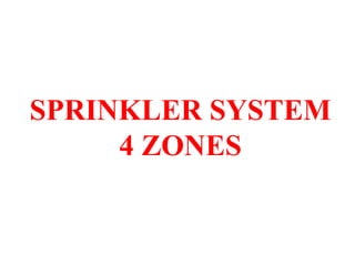

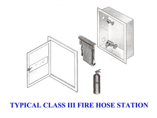

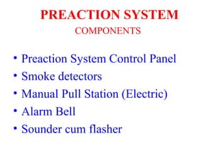
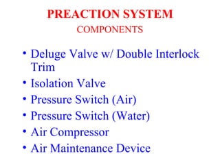
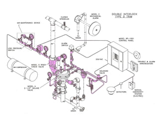
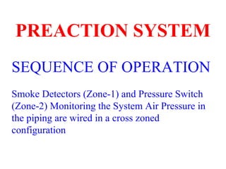
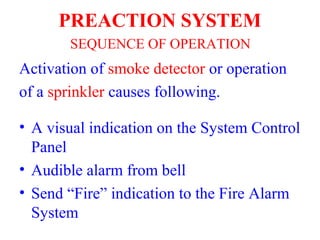

The document describes different types of fire protection systems in a building: 1) A sprinkler system with 4 zones and an alarm valve station. 2) A standpipe system with Class III hose stations for occupants and the fire department. 3) A pre-action system for the electrical substation with smoke detectors, a manual pull station, and components like a deluge valve and air compressor.