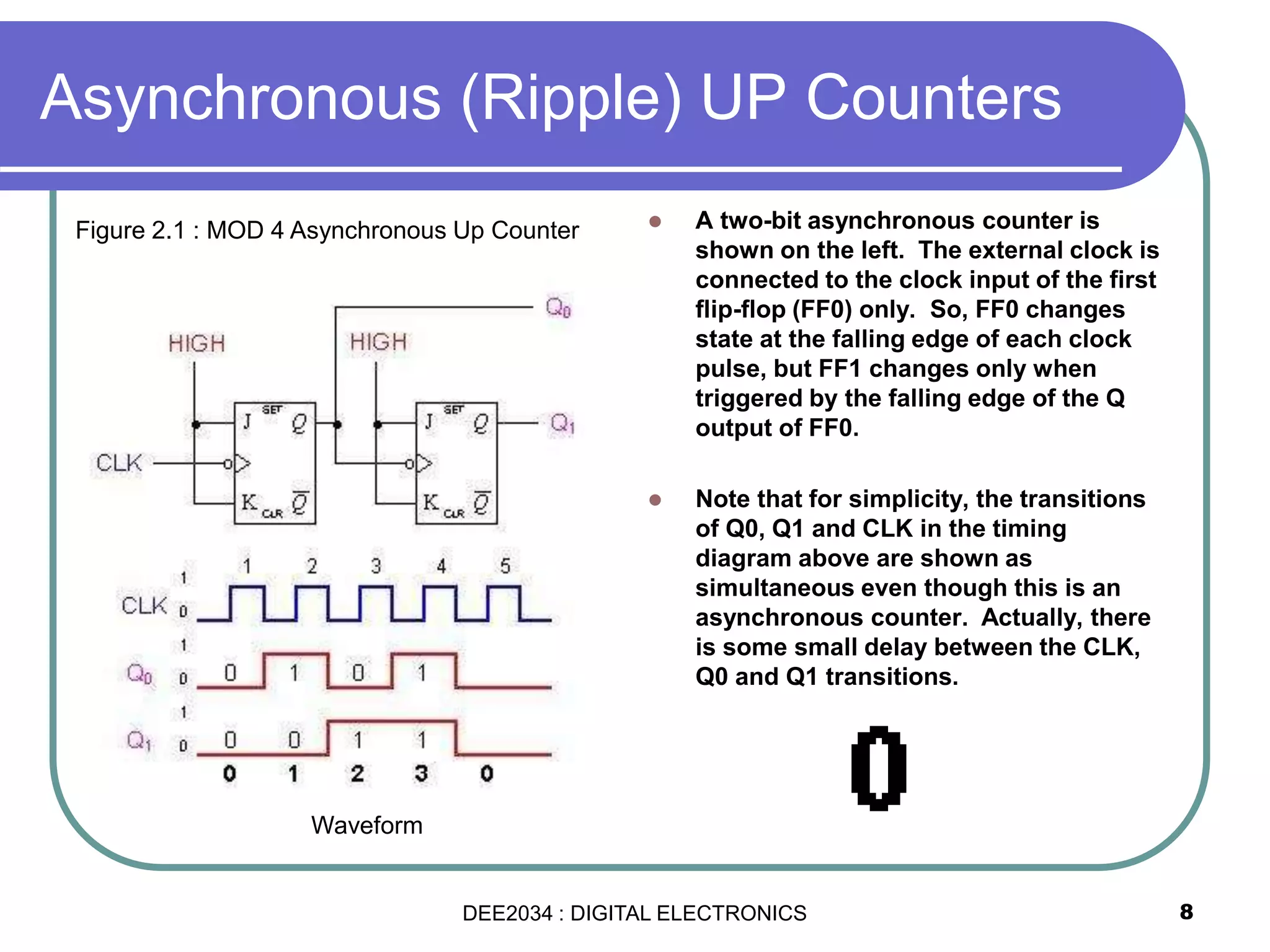
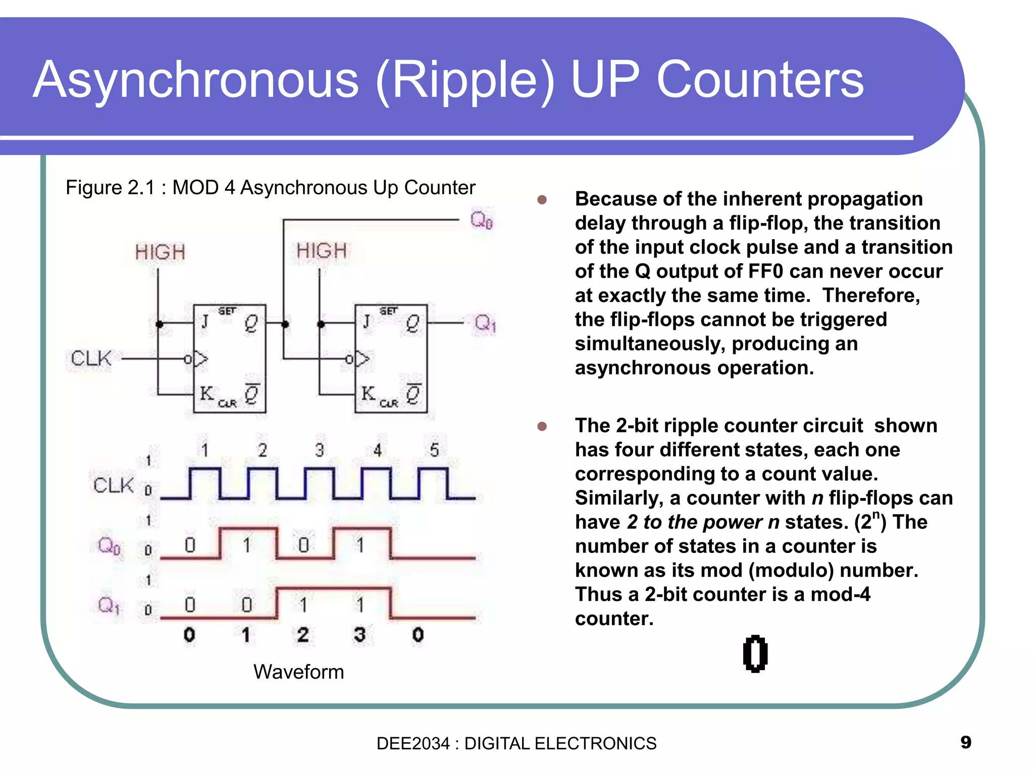
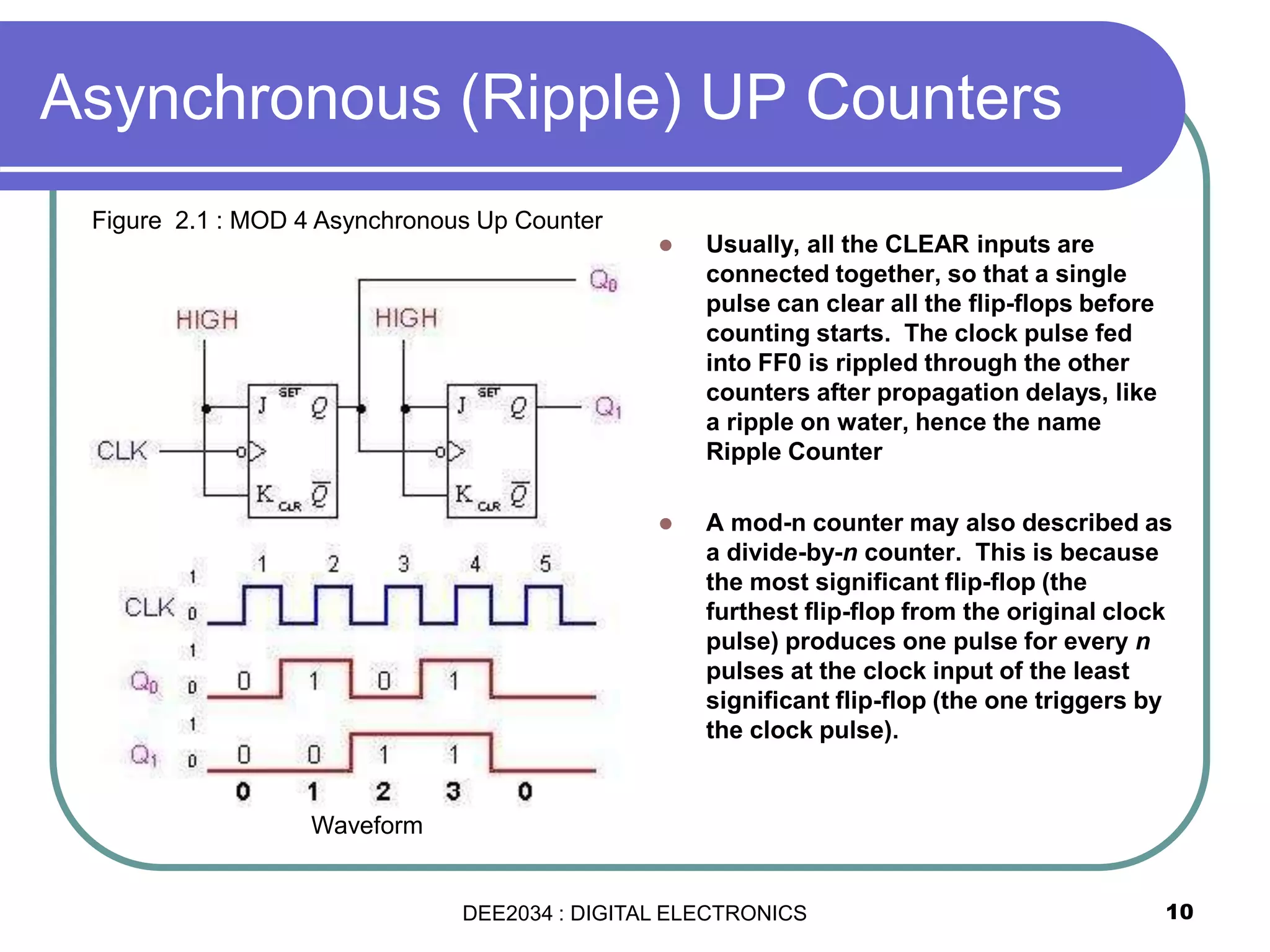
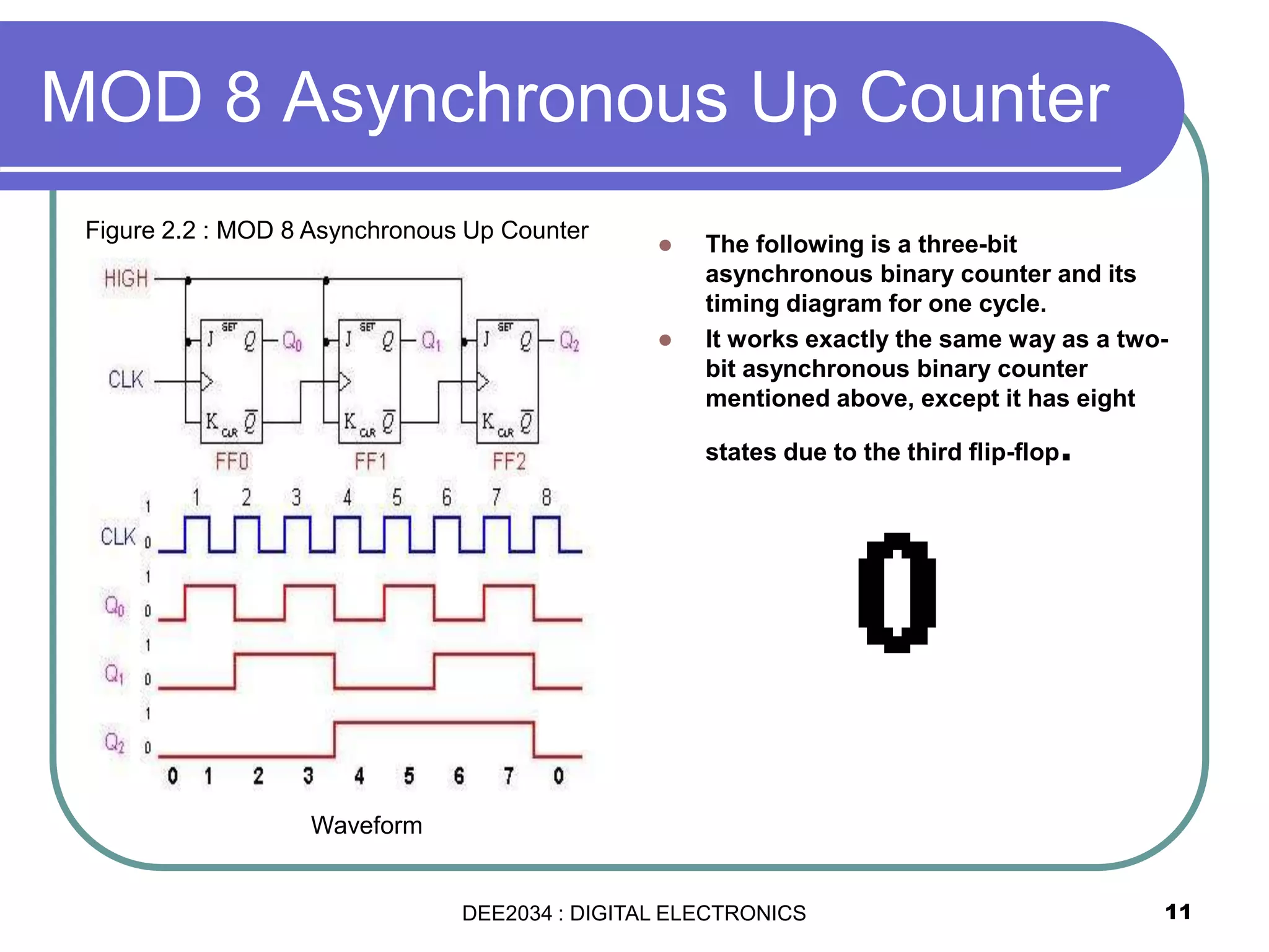
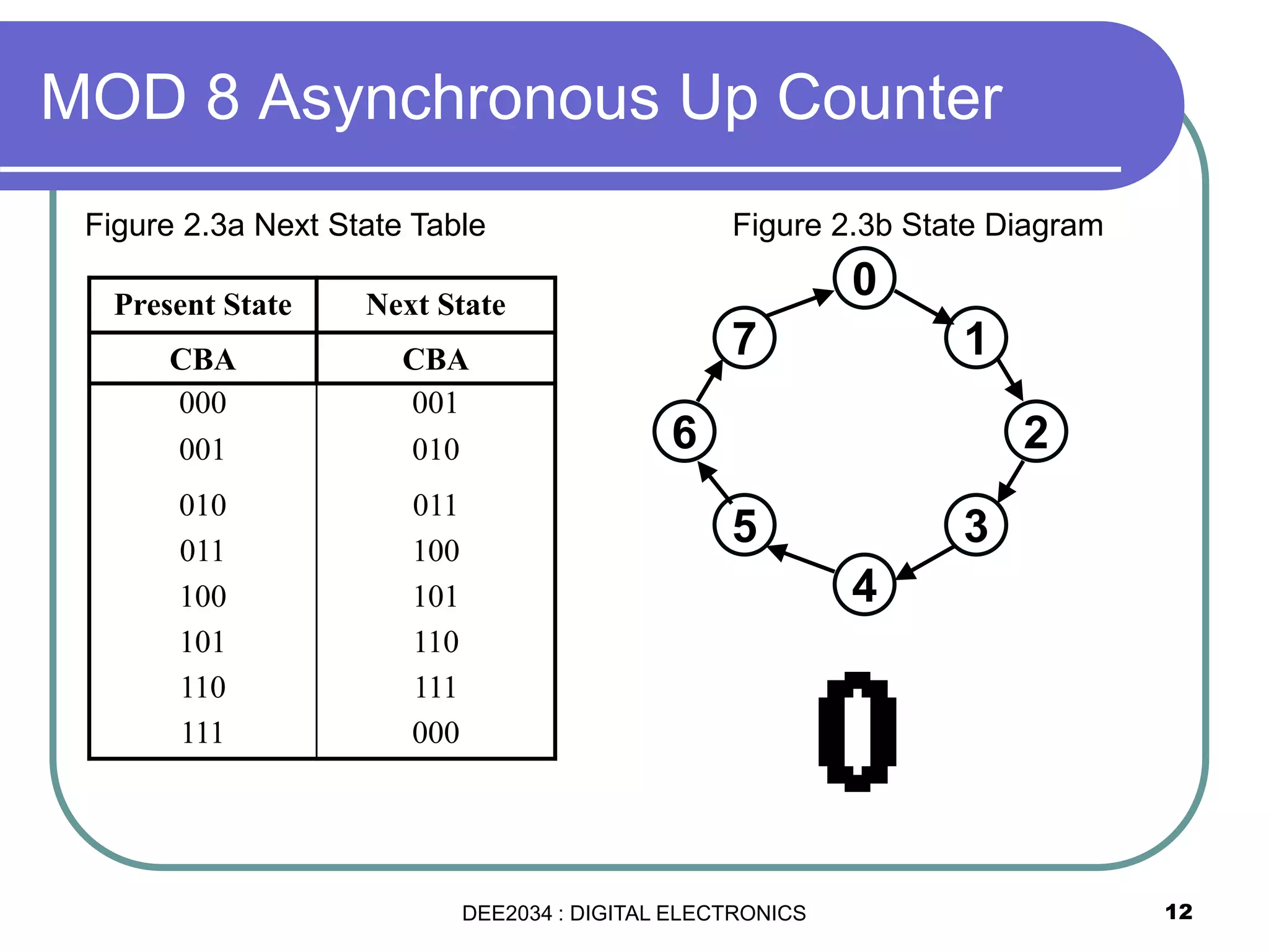
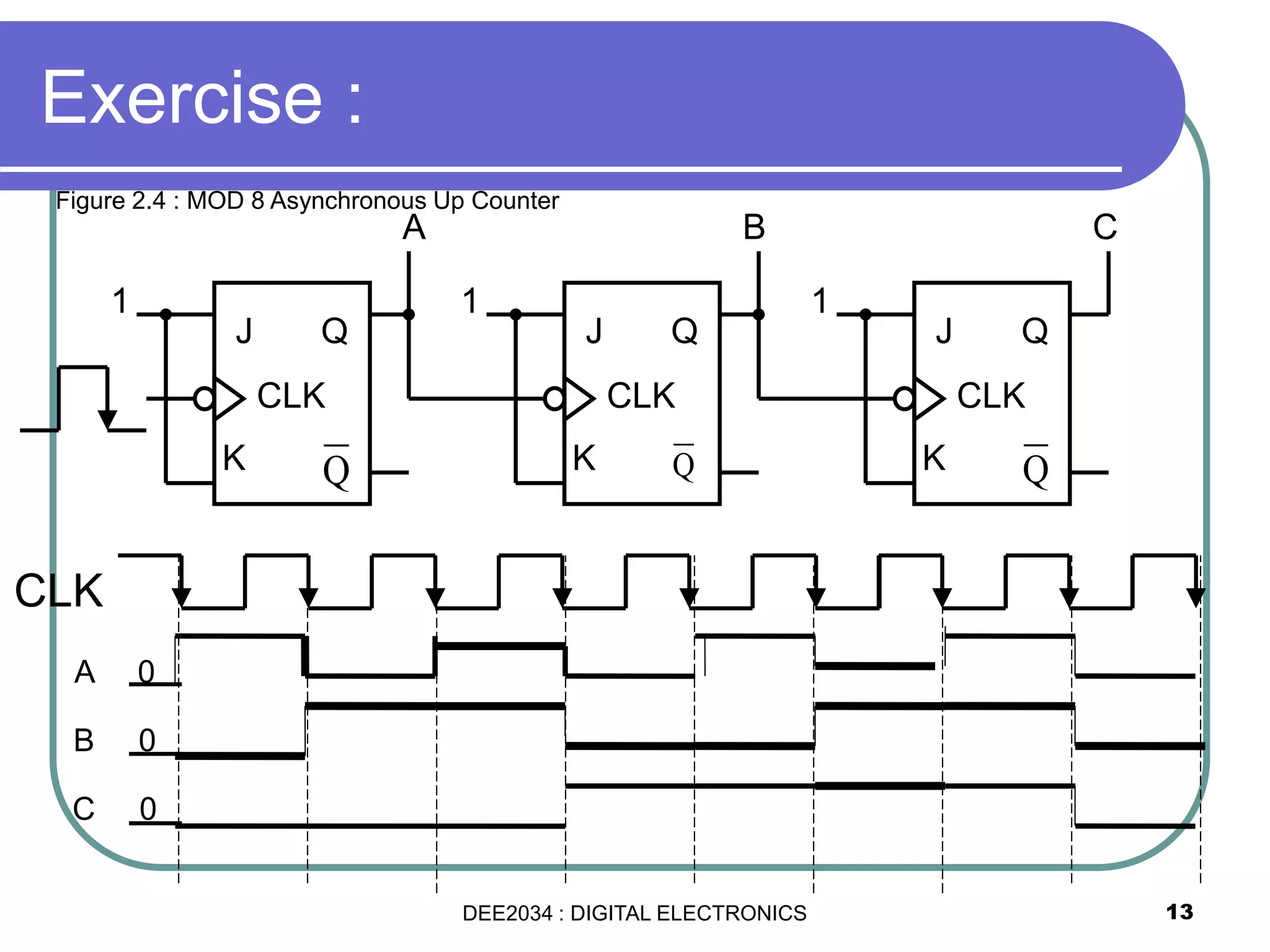
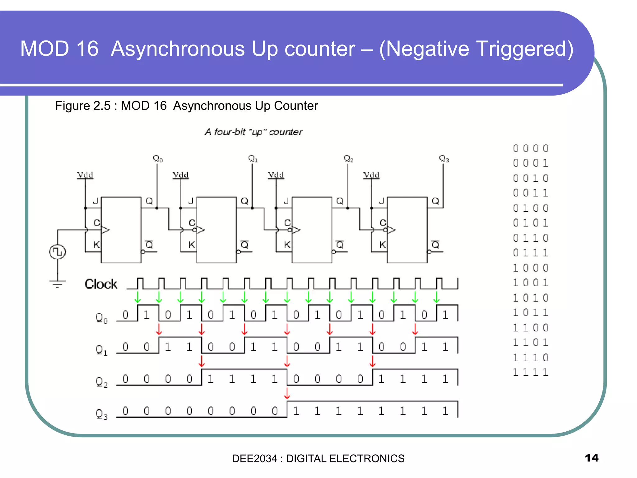
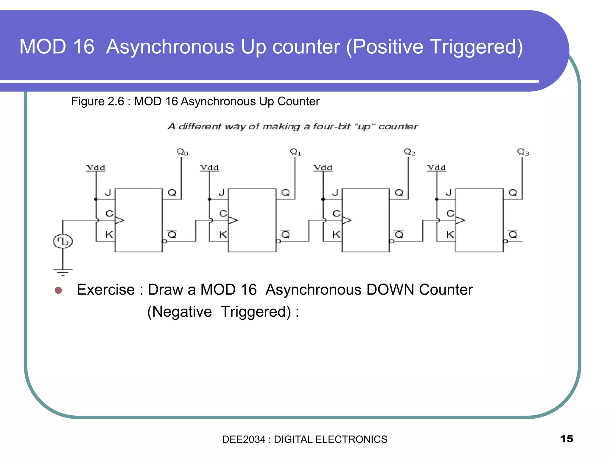
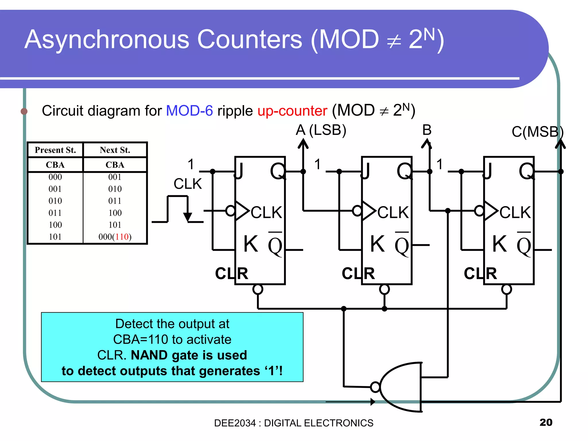
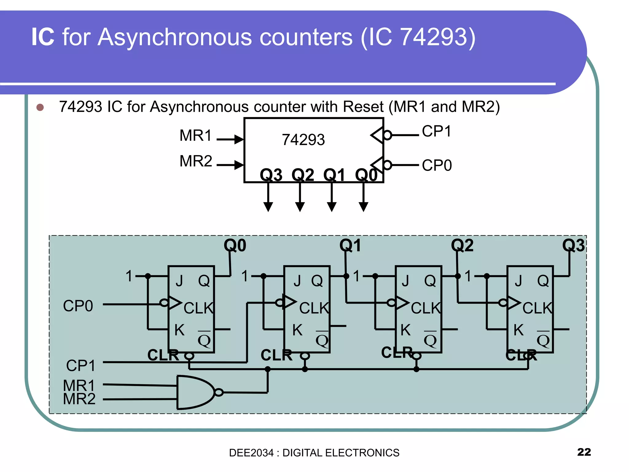
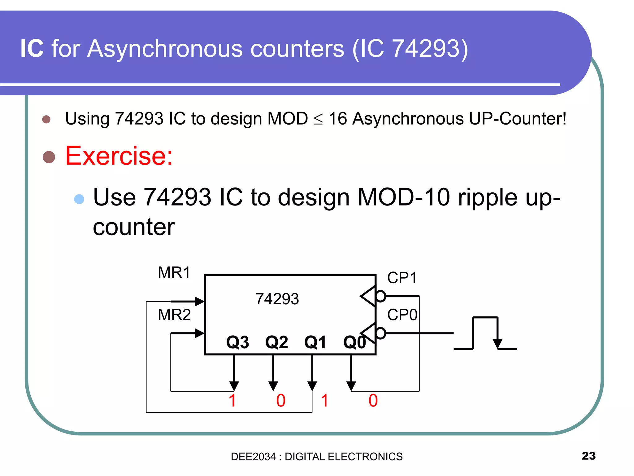
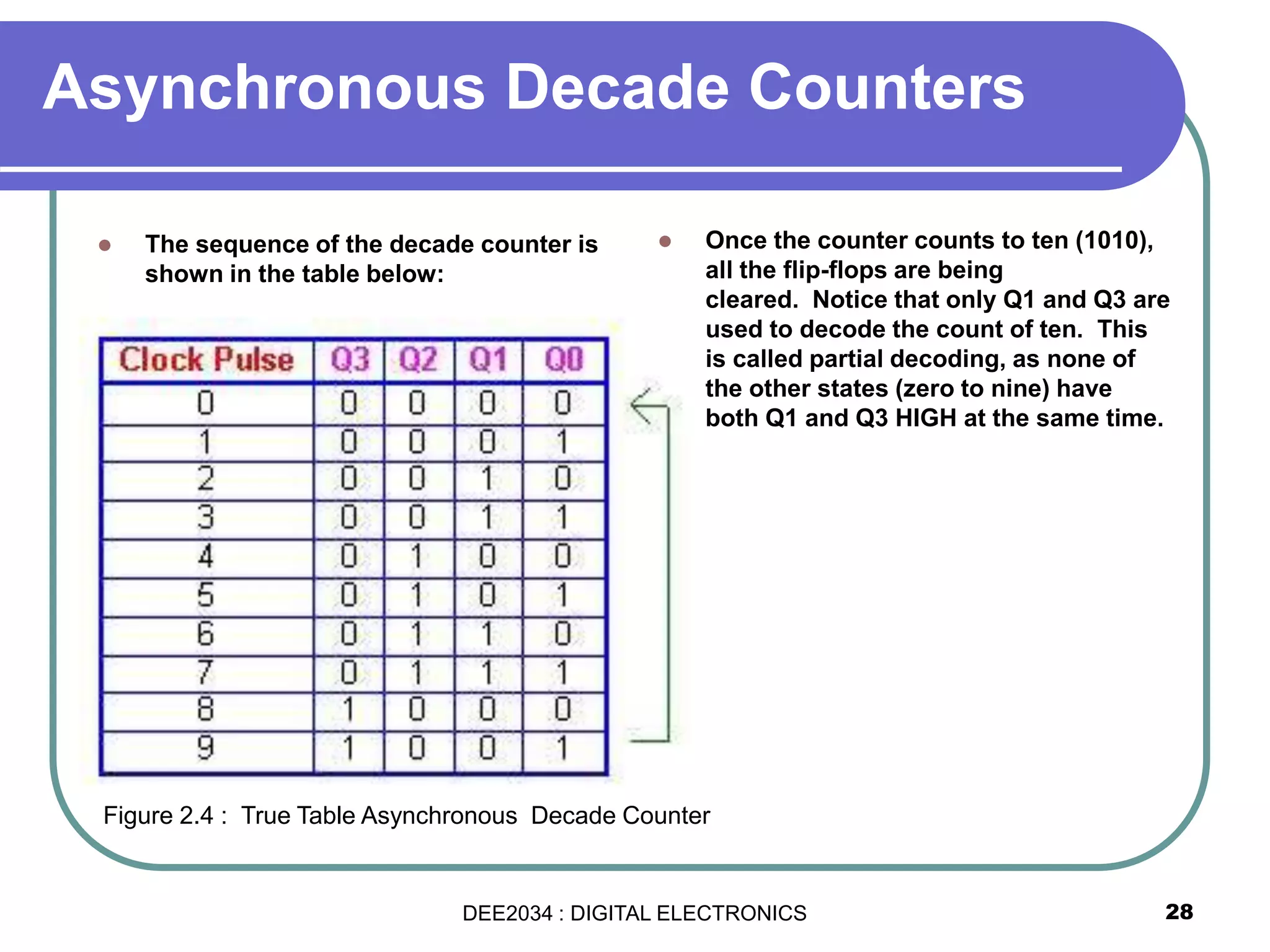
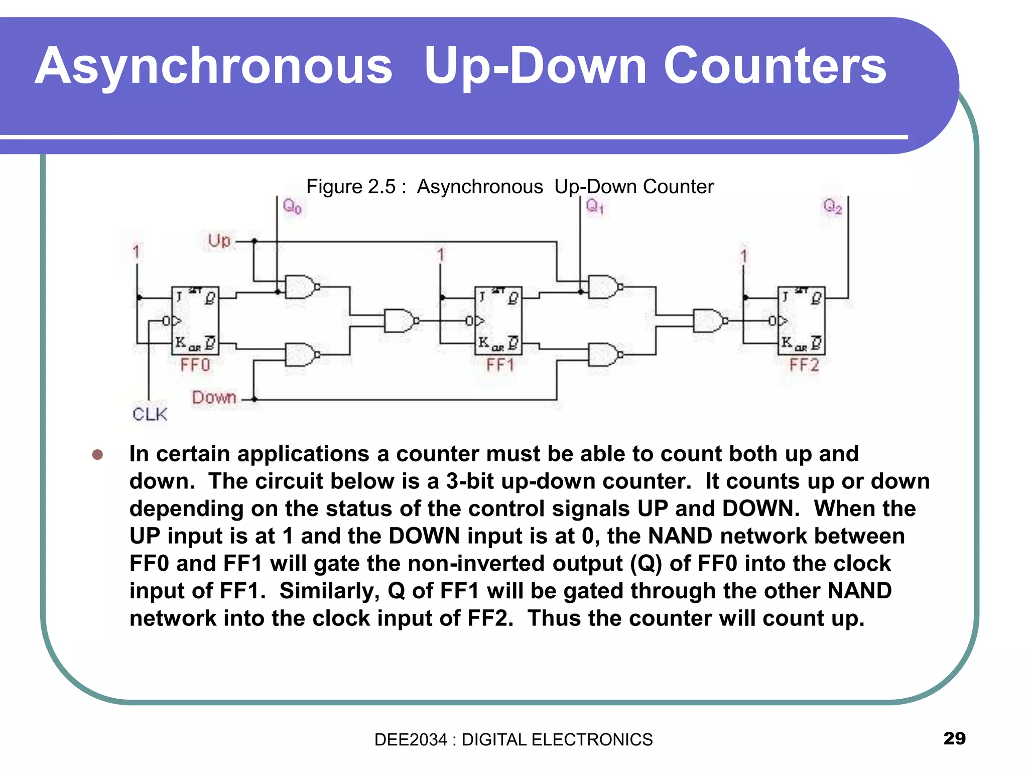
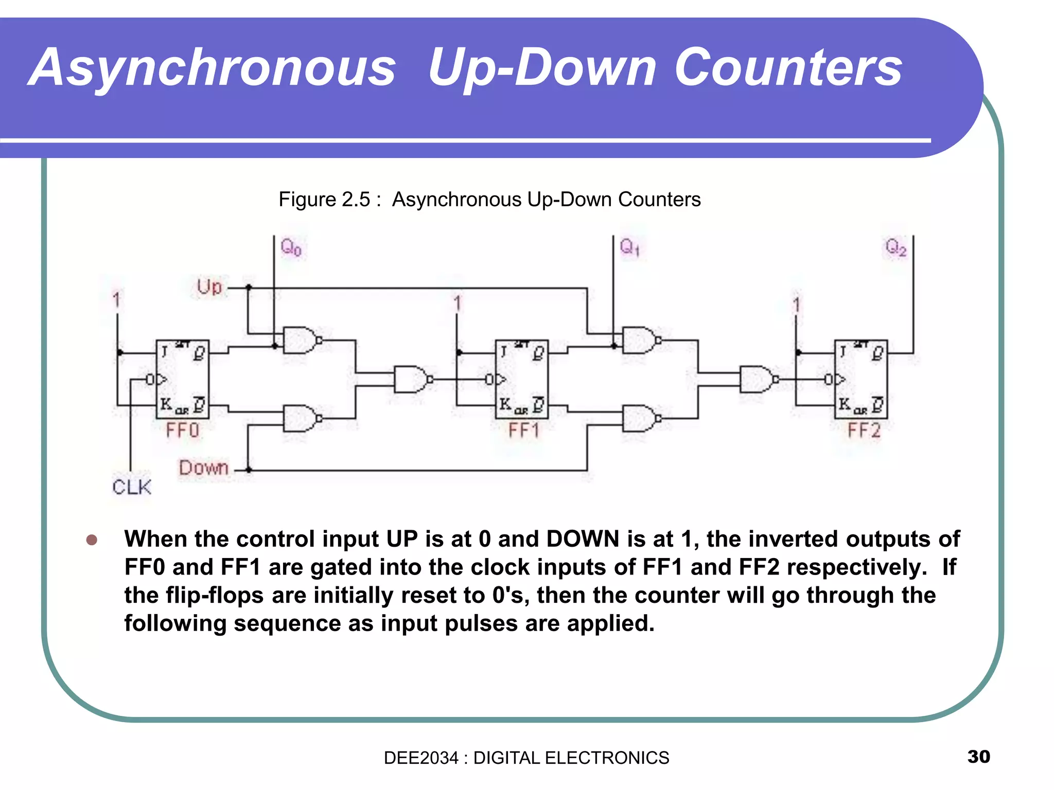
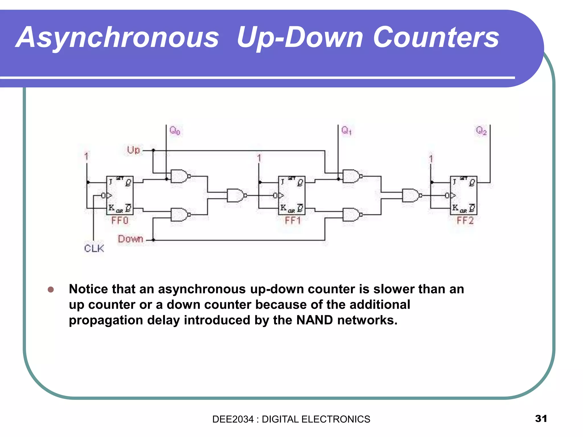
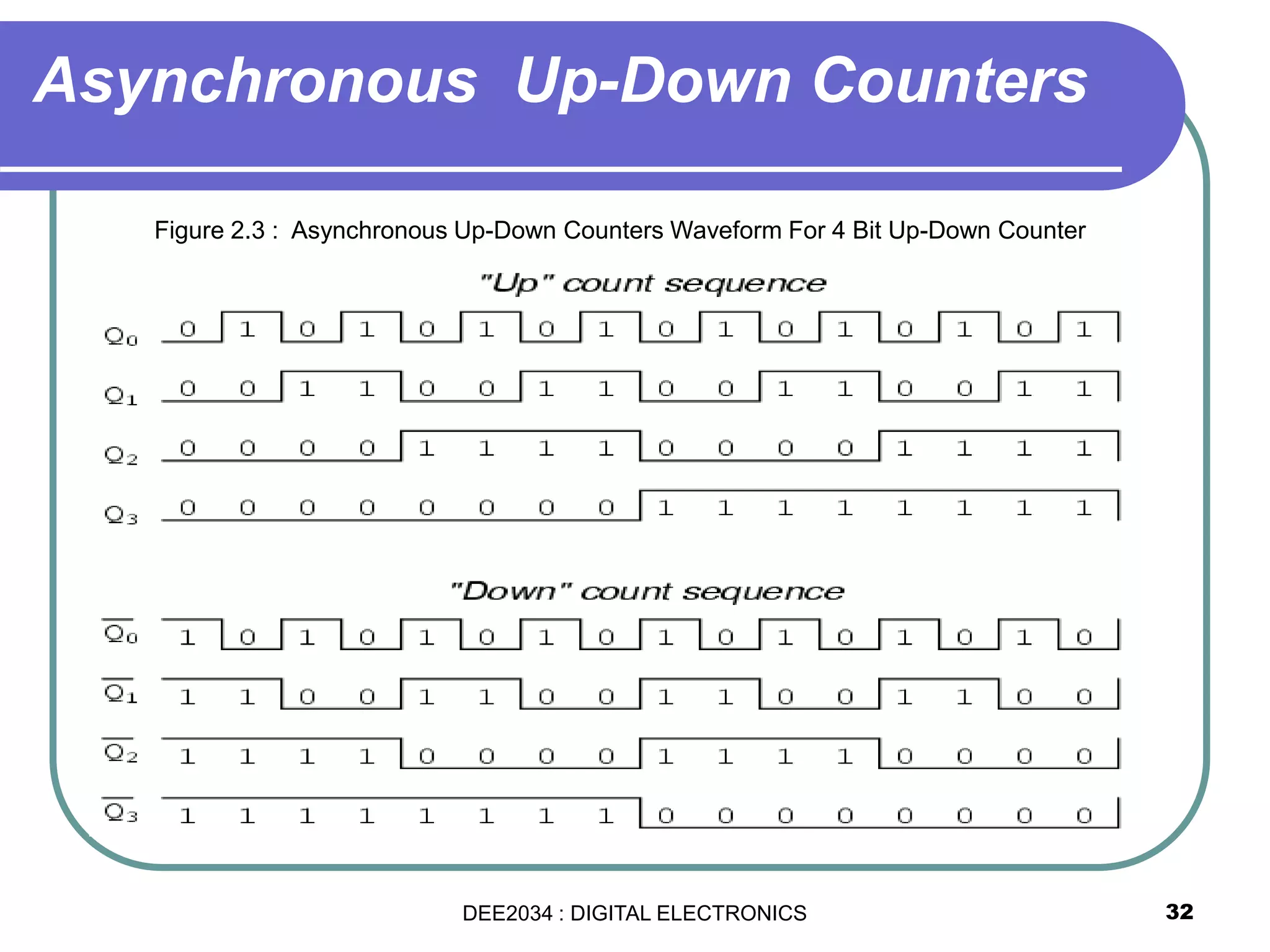
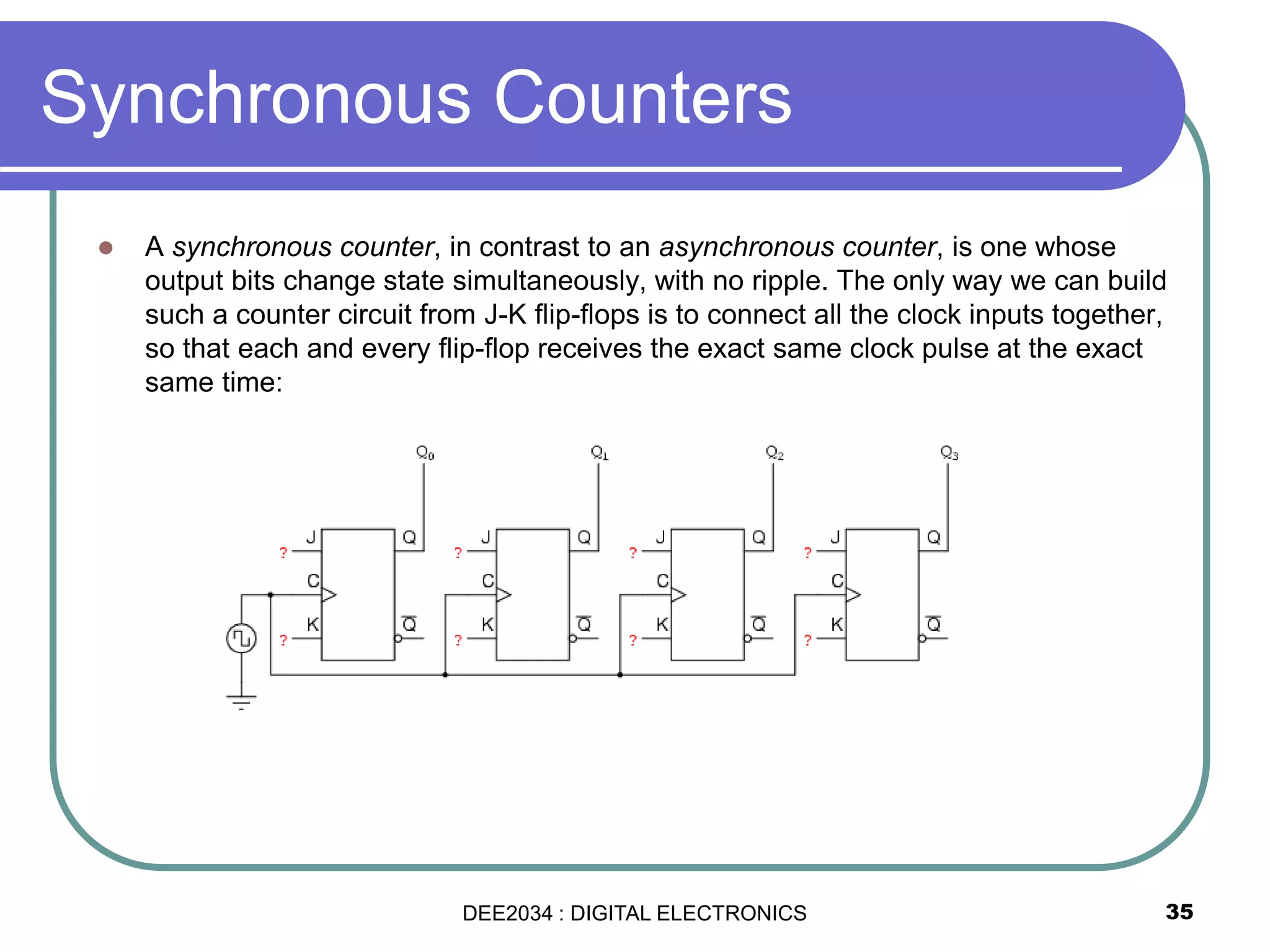
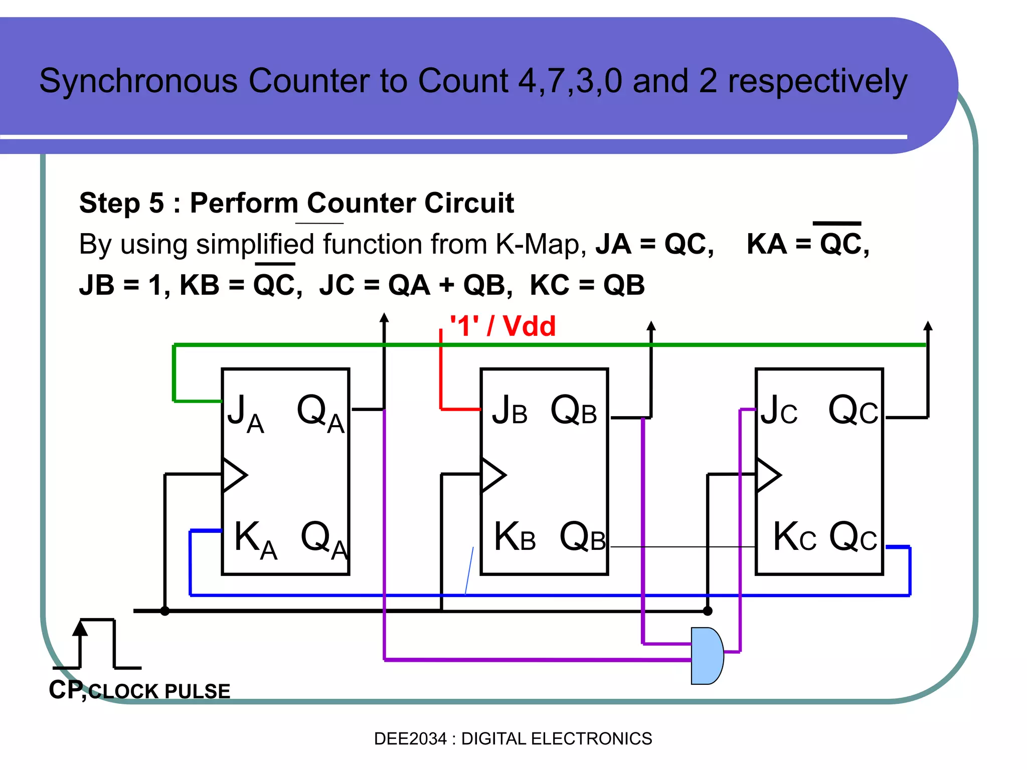
Chapter 5 : Counters
By:Siti Sabariah Salihin
Electrical Engineering Department
1DEE2034 : DIGITAL ELECTRONICS
2
Course Learning Outcomes, CLO
Upon completion of the course, students should be able to:
 CLO 3 : Draw logics diagrams, truth tables and timing diagrams for
all common flip flops and use these to implement sequential logic
circuits correctly.
Chapter 5 : Counters EE 202 DIGITAL ELECTRONICS
DEE2034 : DIGITAL ELECTRONICS
Upon completion of the chapter, students should be able to:
5.1 Understand the basic concepts of asynchronous counter and
synchronous counters, and the difference between them.
5.1.1 Draw circuit and Timing Diagram of Asynchronous
Counters
5.1.2 Interpret the Operation and Application of an
asynchronous counter
5.1.3 Draw circuit and timing diagram of synchronous counters
5.1.4 Interpret the operation and application of synchronous
up/down counters.
5.1.5 Describe how the counters in 5.1.1 and 5.1.3 can be
connected in cascade to produce higher mod
5.1.6 Explain the application of counters in Digital Clock
Chapter 5 : Counters EE 202 DIGITAL ELECTRONICS
DEE2034 : DIGITAL ELECTRONICS
4
Introduction –COUNTERS
 A counter is a register that goes through a predetermined
sequence of states upon the application of clock pulses.
 Asynchronous counters
 Synchronous counters
 Asynchronous Counters (or Ripple counters)
 the clock signal (CLK) is only used to clock the first FF.
 Each FF (except the first FF) is clocked by the preceding FF.
 Synchronous Counters,
 the clock signal (CLK) is applied to all FF, which means that
all FF shares the same clock signal,
 thus the output will change at the same time.
DEE2034 : DIGITAL ELECTRONICS
5
 Modulus (MOD) – the number of states it counts in a complete cycle
before it goes back to the initial state.
 Thus, the number of flip-flops used depends on the MOD of the counter
(ie; MOD-4 use 2 FF (2-bit), MOD-8 use 3 FF (3-bit), etc..)
 Example: MOD-4 Ripple/Asynchronous Up-Counter.
Introduction –COUNTERS
DEE2034 : DIGITAL ELECTRONICS
Asynchronous Counters
6DEE2034 : DIGITAL ELECTRONICS
Asynchronous (Ripple) UP Counters
7
 The Asynchronous Counter that counts 4 number starts from
00011011 and back to 00 is called MOD-4 Ripple (Asynchronous)
Up-Counter.
 Next state table and state diagram
Present State Next State
Q1Q0 Q1Q0
00 01
01 10
10 11
11 00
00
01
10
11
DEE2034 : DIGITAL ELECTRONICS
Asynchronous (Ripple) UP Counters
 A two-bit asynchronous counter is
shown on the left. The external clock is
connected to the clock input of the first
flip-flop (FF0) only. So, FF0 changes
state at the falling edge of each clock
pulse, but FF1 changes only when
triggered by the falling edge of the Q
output of FF0.
 Note that for simplicity, the transitions
of Q0, Q1 and CLK in the timing
diagram above are shown as
simultaneous even though this is an
asynchronous counter. Actually, there
is some small delay between the CLK,
Q0 and Q1 transitions.
8
Figure 2.1 : MOD 4 Asynchronous Up Counter
Waveform
DEE2034 : DIGITAL ELECTRONICS
 Because of the inherent propagation
delay through a flip-flop, the transition
of the input clock pulse and a transition
of the Q output of FF0 can never occur
at exactly the same time. Therefore,
the flip-flops cannot be triggered
simultaneously, producing an
asynchronous operation.
 The 2-bit ripple counter circuit shown
has four different states, each one
corresponding to a count value.
Similarly, a counter with n flip-flops can
have 2 to the power n states. (2n
) The
number of states in a counter is
known as its mod (modulo) number.
Thus a 2-bit counter is a mod-4
counter.
9
Asynchronous (Ripple) UP Counters
Figure 2.1 : MOD 4 Asynchronous Up Counter
Waveform
DEE2034 : DIGITAL ELECTRONICS
Asynchronous (Ripple) UP Counters
 Usually, all the CLEAR inputs are
connected together, so that a single
pulse can clear all the flip-flops before
counting starts. The clock pulse fed
into FF0 is rippled through the other
counters after propagation delays, like
a ripple on water, hence the name
Ripple Counter
 A mod-n counter may also described as
a divide-by-n counter. This is because
the most significant flip-flop (the
furthest flip-flop from the original clock
pulse) produces one pulse for every n
pulses at the clock input of the least
significant flip-flop (the one triggers by
the clock pulse).
10
Figure 2.1 : MOD 4 Asynchronous Up Counter
Waveform
DEE2034 : DIGITAL ELECTRONICS
MOD 8 Asynchronous Up Counter
 The following is a three-bit
asynchronous binary counter and its
timing diagram for one cycle.
 It works exactly the same way as a two-
bit asynchronous binary counter
mentioned above, except it has eight
states due to the third flip-flop.
11
Figure 2.2 : MOD 8 Asynchronous Up Counter
Waveform
DEE2034 : DIGITAL ELECTRONICS
MOD 8 Asynchronous Up Counter
12
Figure 2.3a Next State Table Figure 2.3b State Diagram
Present State Next State
CBA CBA
000 001
001 010
010 011
011 100
100 101
101 110
110 111
111 000
0
1
2
3
7
6
5
4
DEE2034 : DIGITAL ELECTRONICS
Exercise :
13
J Q
K Q
CLK
1
J Q
K Q
CLK
1
J Q
K Q
CLK
1
A B C
CLK
A 0
B 0
C 0
Figure 2.4 : MOD 8 Asynchronous Up Counter
DEE2034 : DIGITAL ELECTRONICS
MOD 16 Asynchronous Up counter – (Negative Triggered)
14
Figure 2.5 : MOD 16 Asynchronous Up Counter
DEE2034 : DIGITAL ELECTRONICS
 Exercise : Draw a MOD 16 Asynchronous DOWN Counter
(Negative Triggered) :
15
MOD 16 Asynchronous Up counter (Positive Triggered)
Figure 2.6 : MOD 16 Asynchronous Up Counter
DEE2034 : DIGITAL ELECTRONICS
Asynchronous DOWN Counter
16
Figure 2.7 : MOD 4 or 2-bit Asynchronous down counter
J Q
K Q
CLK
1
J Q
K Q
CLK
1
A (LSB) B (MSB)
A 0 1 0 1 0 1 0 1 0
B 0 1 1 0 0 1 1 0 0
CLK
Binary 0  3  2  1  0  3  2  1  0
DEE2034 : DIGITAL ELECTRONICS
17
 Exercise:
 Design a MOD-4 ripple down-counter
 Design a MOD-8 ripple down counter
using negative triggered.
 Design a MOD-16 ripple down counter
using positive triggered.
Asynchronous Counters
DEE2034 : DIGITAL ELECTRONICS
18
 So far, we have design the counters with MOD number equal to
2N, where N is the number of bit (N = 1,2,3,4….) (also correspond
to number of FF)
 Thus, the counters are limited on for counting MOD-2, MOD4,
MOD-8, MOD-16 etc..
 The question is how to design a MOD-5, MOD-6, MOD-7, MOD-9
which is not a MOD-2N (MOD  2N) ?
 MOD-6 counters will count from 010 (0002) to 510(1012) and after
that will recount back to 010 (0002) continuously.
Asynchronous Counters (MOD  2N)
DEE2034 : DIGITAL ELECTRONICS
19
MOD-6 ripple up-counter (MOD  2N)
Present St. Next St.
CBA CBA
000 001
001 010
010 011
011 100
100 101
101 000(110)
0
1
2
3
5
4
Reset the state to 0002
when 1102 is detected
Asynchronous Counters (MOD  2N)
Figure 2.8b :State Diagram
Figure 2.8a :Next State Table
DEE2034 : DIGITAL ELECTRONICS
20
Asynchronous Counters (MOD  2N)
 Circuit diagram for MOD-6 ripple up-counter (MOD  2N)
J Q
K
CLR
Q
CLK
1 1 1
A (LSB) B C(MSB)
J Q
K
CLR
Q
CLK
J Q
K
CLR
Q
CLK
Detect the output at
CBA=110 to activate
CLR. NAND gate is used
to detect outputs that generates ‘1’!
CLK
Present St. Next St.
CBA CBA
000 001
001 010
010 011
011 100
100 101
101 000(110)
DEE2034 : DIGITAL ELECTRONICS
21
Exercise : Draw MOD-5 Ripple Down-counter and Up-
counter (MOD  2N)
Asynchronous Counters (MOD  2N)
DEE2034 : DIGITAL ELECTRONICS
22
IC for Asynchronous counters (IC 74293)
 74293 IC for Asynchronous counter with Reset (MR1 and MR2)
MR1
MR2
Q0Q1Q2Q3
CP0
CP1
74293
CLR
Q
CLK
1 1 1
Q0 Q1 Q2
CLR
Q
CLK
CLR
Q
CLK
1
CLR
Q
CLK
Q3
MR1
MR2
CP0
CP1
K K K K
J J J JQ Q Q Q
DEE2034 : DIGITAL ELECTRONICS
23
 Using 74293 IC to design MOD  16 Asynchronous UP-Counter!
 Exercise:
 Use 74293 IC to design MOD-10 ripple up-
counter
MR1
MR2
Q0Q1Q2Q3
CP0
CP1
74293
1 0 1 0
IC for Asynchronous counters (IC 74293)
DEE2034 : DIGITAL ELECTRONICS
24
 Exercise:
 Determine the MOD for each configuration shown below?
MR1
MR2
Q0Q1Q2Q3
CP0
CP1
74293
MR1
MR2
Q0Q1Q2Q3
CP0
CP1
74293
1 0 1
IC for Asynchronous counters (IC 74293)
Answer : MOD 8
Answer : MOD 5
DEE2034 : DIGITAL ELECTRONICS
25
 Determine the MOD for configuration shown below?
MR1
MR2
Q0Q1Q2Q3
CP0
CP1
74293
Answer : MOD 14
IC for Asynchronous counters (IC 74293)
1 1 1
1
DEE2034 : DIGITAL ELECTRONICS
26
IC for Asynchronous counters (IC 74293)
Exercise : Design Asynchronous counters MOD-60
using IC 74293.
Solution : Discuss with your Lecturer in class.
Exercise : i. Design Asynchronous counters MOD-55
using IC 74293.
ii. Design Asynchronous counters MOD-
1000 using IC 74293.
CASCADE connection to produce Higher Mod
DEE2034 : DIGITAL ELECTRONICS
Asynchronous Decade Counters
 The binary counters previously introduced have two to the power n states. But
counters with states less than this number are also possible. They are designed to
have the number of states in their sequences, which are called truncated
sequences. These sequences are achieved by forcing the counter to recycle before
going through all of its normal states.
 A common modulus for counters with truncated sequences is ten. A counter with
ten states in its sequence is called a decade counter. The circuit below is an
implementation of a decade counter.
27
Figure 2.3 : Asynchronous Decade Counter
DEE2034 : DIGITAL ELECTRONICS
 The sequence of the decade counter is
shown in the table below:
 Once the counter counts to ten (1010),
all the flip-flops are being
cleared. Notice that only Q1 and Q3 are
used to decode the count of ten. This
is called partial decoding, as none of
the other states (zero to nine) have
both Q1 and Q3 HIGH at the same time.
28
Asynchronous Decade Counters
Figure 2.4 : True Table Asynchronous Decade Counter
DEE2034 : DIGITAL ELECTRONICS
Asynchronous Up-Down Counters
 In certain applications a counter must be able to count both up and
down. The circuit below is a 3-bit up-down counter. It counts up or down
depending on the status of the control signals UP and DOWN. When the
UP input is at 1 and the DOWN input is at 0, the NAND network between
FF0 and FF1 will gate the non-inverted output (Q) of FF0 into the clock
input of FF1. Similarly, Q of FF1 will be gated through the other NAND
network into the clock input of FF2. Thus the counter will count up.
29
Figure 2.5 : Asynchronous Up-Down Counter
DEE2034 : DIGITAL ELECTRONICS
 When the control input UP is at 0 and DOWN is at 1, the inverted outputs of
FF0 and FF1 are gated into the clock inputs of FF1 and FF2 respectively. If
the flip-flops are initially reset to 0's, then the counter will go through the
following sequence as input pulses are applied.
30
Asynchronous Up-Down Counters
Figure 2.5 : Asynchronous Up-Down Counters
DEE2034 : DIGITAL ELECTRONICS
 Notice that an asynchronous up-down counter is slower than an
up counter or a down counter because of the additional
propagation delay introduced by the NAND networks.
31
Asynchronous Up-Down Counters
DEE2034 : DIGITAL ELECTRONICS
32
Asynchronous Up-Down Counters
Figure 2.3 : Asynchronous Up-Down Counters Waveform For 4 Bit Up-Down Counter
DEE2034 : DIGITAL ELECTRONICS
33
 Disadvantages of Asynchronous Counters:-
 Propagation delay is severe for larger MOD of counters, especially
at the MSB.
 Existence of ‘glitch’ is inevitable for MOD  2N counters.
 Cannot design random counters (i.e:- to design circuit that counts
numbers in these sequence
56723156723156….)
 Solution, use SYNCHRONOUS COUNTERS.
Asynchronous Counters
DEE2034 : DIGITAL ELECTRONICS
Synchronous Counters
34DEE2034 : DIGITAL ELECTRONICS
Synchronous Counters
 A synchronous counter, in contrast to an asynchronous counter, is one whose
output bits change state simultaneously, with no ripple. The only way we can build
such a counter circuit from J-K flip-flops is to connect all the clock inputs together,
so that each and every flip-flop receives the exact same clock pulse at the exact
same time:
35DEE2034 : DIGITAL ELECTRONICS
 Now, the question is, what do we do with the J and K inputs? We know that we still have to
maintain the same divide-by-two frequency pattern in order to count in a binary sequence, and
that this pattern is best achieved utilizing the "toggle" mode of the flip-flop, so the fact that the
J and K inputs must both be (at times) "high" is clear. However, if we simply connect all the J
and K inputs to the positive rail of the power supply as we did in the asynchronous circuit, this
would clearly not work because all the flip-flops would toggle at the same time: with each and
every clock pulse!
Synchronous Counters
36DEE2034 : DIGITAL ELECTRONICS
Synchronous Counters
37DEE2034 : DIGITAL ELECTRONICS
Synchronous Counters
38DEE2034 : DIGITAL ELECTRONICS
39
 For synchronous counters, all the flip-flops are using the
same CLOCK signal. Thus, the output would change
synchronously.
 Procedure to design synchronous counter are as follows:-
STEP 1: Obtain the State Diagram.
STEP 2: Obtain the Excitation Table using state transition
table for any particular FF (JK or D). Determine number
of FF used.
STEP 3: Obtain and simplify the function of each FF input
using K-Map.
STEP 4: Draw the circuit.
How To Design Synchronous Counter
DEE2034 : DIGITAL ELECTRONICS
40
 Design a MOD-4 synchronous up-counter,
using JK FF.
STEP 1: Obtain the State transition Diagram
0
1
2
3
00
01
10
11Binary
How To Design Synchronous Counter
DEE2034 : DIGITAL ELECTRONICS
41
STEP 2: Obtain the Excitation table. Two JK FF are used.
Present State Next State Input, J K
B A B A JB KB JA KA
0 0 0 1 0 X 1 X
0 1 1 0 1 X X 1
1 0 1 1 X 0 1 X
1 1 0 0 X 1 X 1
OUTPUT TRANSITION
QN QN+1
FF INPUT
J K
0  0 0 X
0  1 1 X
1  0 X 1
1  1 X 0
Excitation table
How To Design Synchronous Counter
DEE2034 : DIGITAL ELECTRONICS
42
STEP 3: Obtain the simplified function using K-Map
B
A 0 1
0 0 1
1 X X
JB = A
B
A 0 1
0 X X
1 0 1
KB = A
B
A 0 1
0 1 X
1 1 X
JA = 1
B
A 0 1
0 X 1
1 X 1
KA = 1
How To Design Synchronous Counter
DEE2034 : DIGITAL ELECTRONICS
43
STEP 4: Draw the circuit diagram.
(MOD-4 synchronous up-counter )
JA QA
KA A
Q
CLK
1
JB QB
KB B
Q
CLK
A (LSB) B (MSB)
How To Design Synchronous Counter
DEE2034 : DIGITAL ELECTRONICS
How To design Synchronous Counter
 Let us employ these techniques to design a MOD-8 counter to count in the
following sequence: 0, 1, 2, 3, 4, 5, 6, 7.
 Step1: Determined Flip Flop Used and Creating state transition
diagram. (Rajah Keadaan)
N = 2
n
8 = 2
n
n = log 8 / log 2
= 3 Flip Flop ( 3 Bit )
M = 2
n
-1
= 23
- 1 = 8 - 1 = 7
44
N = Modulo/MOD
n = Flip Flop Used
M = Maximum Number To Be Count
DEE2034 : DIGITAL ELECTRONICS
 Step 2: Creating present state-next state table
45
How To design Synchronous Counter
Present State Next State
Q2 Q1 Q0 Q2 Q1 Q0
0 0 0 0 0 1
0 0 1 0 1 0
0 1 0 0 1 1
0 1 1 1 0 0
1 0 0 1 0 1
1 0 1 1 1 0
1 1 0 1 1 1
1 1 1 0 0 0
Q0 = QA
Q1 = QB
Q2 = Qc
DEE2034 : DIGITAL ELECTRONICS
 Step 3: Expand the present state-next state table to form the transition
table.
46
How To Design Synchronous Counter
Present
State
Next State Present inputs
QC QB QA QC QB QA JCKC JBKB JAKA
0 0 0 0 0 1 0X 0X 1X
0 0 1 0 1 0 0X 1X X1
0 1 0 0 1 1 0X X0 1X
0 1 1 1 0 0 1X X1 X1
1 0 0 1 0 1 X0 0X 1X
1 0 1 1 1 0 X0 1X X1
1 1 0 1 1 1 X0 X0 1X
1 1 1 0 0 0 X1 X1 X1
Excitation Table
(Jadual Ujaan Flip Flop
JK)
Q Q J K
0 0 0 X
0 1 1 X
1 0 X 1
1 1 X 0
_
‘X’ indicates a "don’t care" condition.
DEE2034 : DIGITAL ELECTRONICS
 Step 4: Use Karnaugh maps to identify the present state logic functions
for each of the inputs.
E.g. for J2 we get:
47
How To Design Synchronous Counter
JC = QBQA
Using similar techniques for the other inputs we get:
KC = QBQA
JB = QA
KB = QA
JA = 1
KA = 1
0 2 6 4
1 3 7 5
QA
QA
1 1 1 00100
QcQB QcQB
0
1 0
0 0
1
X
X
X
X
DEE2034 : DIGITAL ELECTRONICS
 Step 5: Constructing Circuit
48
How To Design Synchronous Counter
A
A
A
A B
B
C
C
C
C
B
B
DEE2034 : DIGITAL ELECTRONICS
Example :
Design a Synchronous Counter to Count 4,7,3,0 and 2 respectively
using JKFlip Flop negative trigered by showing:
i. Flip Flop Used
ii. State Transition Diagram
iii. Exitation Table / Present state, next State
iv. Karnough Map & perform Simplified Function
v. The Synchronous Counter
How To Design Synchronous Counter
that count Random number
DEE2034 : DIGITAL ELECTRONICS
Solution:
Step 1 : Flip Flop Used
Find Modulo, N= 2
n
M = 7, M = 2
n
-1 = 7
2
n
= N , so, N = 7+1 = 8, MOD 8
2
n
= 8, n = log 8 / log 2
n = 3 bit = 3 Flip Flop.
Synchronous Counter to Count 4,7,3,0 and 2 respectively
DEE2034 : DIGITAL ELECTRONICS
Solution:
Step 2 : State Transation
Diagram, to count 4, 7, 3, 0
and 2.
100
000
111
011
010
Synchronous Counter to Count 4,7,3,0 and 2 respectively
Present
Qn
Next
State
Qn+1
J K
0 0 0 x
0 1 1 x
1 0 x 1
1 1 x 0
Exitation Truth Table For Counter
using JK FlipFlop
DEE2034 : DIGITAL ELECTRONICS
Step 3 : Exitation Table /present State, Next State
Synchronous Counter to Count 4,7,3,0 and 2 respectively
Deci
mal
Present
State
Next State JC KC JB KB JA KA
QC QB QA QC QB QA
4 1 0 0 1 1 1 x 0 1 x 1 x
7 1 1 1 0 1 1 x 1 x 0 x 0
3 0 1 1 0 0 0 0 x x 1 x 1
0 0 0 0 0 1 0 0 x 1 x 0 x
2 0 1 0 1 0 0 1 x x 1 0 x
DEE2034 : DIGITAL ELECTRONICS
Step 4: Karnough Map and
Simplified Function
Synchronous Counter to Count 4,7,3,0 and 2 respectively
00 01 11 10
0
0 0 x 1
1
x x x x
K-Map For
JA = QC
CB
A
0
3
42
1 5
6
7
DEE2034 : DIGITAL ELECTRONICS
00 01 11 10
0 0 0 X 1
1 X X X X
00 01 11 10
0 X X X X
1 X 1 0 X
K-Map For
JA = QC
K-Map For
KA = QC
Synchronous Counter to Count 4,7,3,0 and 2 respectively
CB
A
0
3
42
1 5
6
7
CB
A
0
3
42
1 5
6
7
DEE2034 : DIGITAL ELECTRONICS
00 01 11 10
0 1 X X 1
1 X X X X
00 01 11 10
0 X 1 X X
1 X 1 0 X
K-Map For
JB = 1
K-Map For
KB = QC
Synchronous Counter to Count 4,7,3,0 and 2 respectively
CB
A
0
3
42
1 5
6
7
CB
A
0
3
42
1 5
6
7
DEE2034 : DIGITAL ELECTRONICS
00 01 11 10
0 0 1 X X
1 X 0 X X
00 01 11 10
0 X X X 0
1 X X 1 X
K-Map For
JC = QAQB
K-Map For
KC = QB
Synchronous Counter to Count 4,7,3,0 and 2 respectively
CB
A
0
3
42
1 5
6
7
CB
A
0
3
42
1 5
6
7
DEE2034 : DIGITAL ELECTRONICS
Step 5 : Perform Counter Circuit
By using simplified function from K-Map, JA = QC, KA = QC,
JB = 1, KB = QC, JC = QA + QB, KC = QB
'1' / Vdd
Synchronous Counter to Count 4,7,3,0 and 2 respectively
JA QA
KA QA
JB QB
KB QB
JC QC
KC QC
CP,CLOCK PULSE
DEE2034 : DIGITAL ELECTRONICS
Synchronous Counter
Exercises:
 Design a counter to count in the following
sequence: 6, 4. 2, 3, 1.
 Design a counter to count in the following
sequence: 15,9,11,5,2,13,1.
 Do more exercises in Past Years Exam Paper.
End Of This Topic…..
58DEE2034 : DIGITAL ELECTRONICS
59
Download Tutorials Chapter 5: Counter
http://www.portal.cidos.edu.my
REFERENCES:
1. "Digital Systems Principles And Application"
Sixth Editon, Ronald J. Tocci.
2. "Digital Systems Fundamentals"
P.W Chandana Prasad, Lau Siong Hoe,
Dr. Ashutosh Kumar Singh, Muhammad Suryanata.
DEE2034 : DIGITAL ELECTRONICS

Dee2034 chapter 5 counter

  • 1.
    Chapter 5 :Counters By:Siti Sabariah Salihin Electrical Engineering Department 1DEE2034 : DIGITAL ELECTRONICS
  • 2.
    2 Course Learning Outcomes,CLO Upon completion of the course, students should be able to:  CLO 3 : Draw logics diagrams, truth tables and timing diagrams for all common flip flops and use these to implement sequential logic circuits correctly. Chapter 5 : Counters EE 202 DIGITAL ELECTRONICS DEE2034 : DIGITAL ELECTRONICS
  • 3.
    Upon completion ofthe chapter, students should be able to: 5.1 Understand the basic concepts of asynchronous counter and synchronous counters, and the difference between them. 5.1.1 Draw circuit and Timing Diagram of Asynchronous Counters 5.1.2 Interpret the Operation and Application of an asynchronous counter 5.1.3 Draw circuit and timing diagram of synchronous counters 5.1.4 Interpret the operation and application of synchronous up/down counters. 5.1.5 Describe how the counters in 5.1.1 and 5.1.3 can be connected in cascade to produce higher mod 5.1.6 Explain the application of counters in Digital Clock Chapter 5 : Counters EE 202 DIGITAL ELECTRONICS DEE2034 : DIGITAL ELECTRONICS
  • 4.
    4 Introduction –COUNTERS  Acounter is a register that goes through a predetermined sequence of states upon the application of clock pulses.  Asynchronous counters  Synchronous counters  Asynchronous Counters (or Ripple counters)  the clock signal (CLK) is only used to clock the first FF.  Each FF (except the first FF) is clocked by the preceding FF.  Synchronous Counters,  the clock signal (CLK) is applied to all FF, which means that all FF shares the same clock signal,  thus the output will change at the same time. DEE2034 : DIGITAL ELECTRONICS
  • 5.
    5  Modulus (MOD)– the number of states it counts in a complete cycle before it goes back to the initial state.  Thus, the number of flip-flops used depends on the MOD of the counter (ie; MOD-4 use 2 FF (2-bit), MOD-8 use 3 FF (3-bit), etc..)  Example: MOD-4 Ripple/Asynchronous Up-Counter. Introduction –COUNTERS DEE2034 : DIGITAL ELECTRONICS
  • 6.
  • 7.
    Asynchronous (Ripple) UPCounters 7  The Asynchronous Counter that counts 4 number starts from 00011011 and back to 00 is called MOD-4 Ripple (Asynchronous) Up-Counter.  Next state table and state diagram Present State Next State Q1Q0 Q1Q0 00 01 01 10 10 11 11 00 00 01 10 11 DEE2034 : DIGITAL ELECTRONICS
  • 8.
    Asynchronous (Ripple) UPCounters  A two-bit asynchronous counter is shown on the left. The external clock is connected to the clock input of the first flip-flop (FF0) only. So, FF0 changes state at the falling edge of each clock pulse, but FF1 changes only when triggered by the falling edge of the Q output of FF0.  Note that for simplicity, the transitions of Q0, Q1 and CLK in the timing diagram above are shown as simultaneous even though this is an asynchronous counter. Actually, there is some small delay between the CLK, Q0 and Q1 transitions. 8 Figure 2.1 : MOD 4 Asynchronous Up Counter Waveform DEE2034 : DIGITAL ELECTRONICS
  • 9.
     Because ofthe inherent propagation delay through a flip-flop, the transition of the input clock pulse and a transition of the Q output of FF0 can never occur at exactly the same time. Therefore, the flip-flops cannot be triggered simultaneously, producing an asynchronous operation.  The 2-bit ripple counter circuit shown has four different states, each one corresponding to a count value. Similarly, a counter with n flip-flops can have 2 to the power n states. (2n ) The number of states in a counter is known as its mod (modulo) number. Thus a 2-bit counter is a mod-4 counter. 9 Asynchronous (Ripple) UP Counters Figure 2.1 : MOD 4 Asynchronous Up Counter Waveform DEE2034 : DIGITAL ELECTRONICS
  • 10.
    Asynchronous (Ripple) UPCounters  Usually, all the CLEAR inputs are connected together, so that a single pulse can clear all the flip-flops before counting starts. The clock pulse fed into FF0 is rippled through the other counters after propagation delays, like a ripple on water, hence the name Ripple Counter  A mod-n counter may also described as a divide-by-n counter. This is because the most significant flip-flop (the furthest flip-flop from the original clock pulse) produces one pulse for every n pulses at the clock input of the least significant flip-flop (the one triggers by the clock pulse). 10 Figure 2.1 : MOD 4 Asynchronous Up Counter Waveform DEE2034 : DIGITAL ELECTRONICS
  • 11.
    MOD 8 AsynchronousUp Counter  The following is a three-bit asynchronous binary counter and its timing diagram for one cycle.  It works exactly the same way as a two- bit asynchronous binary counter mentioned above, except it has eight states due to the third flip-flop. 11 Figure 2.2 : MOD 8 Asynchronous Up Counter Waveform DEE2034 : DIGITAL ELECTRONICS
  • 12.
    MOD 8 AsynchronousUp Counter 12 Figure 2.3a Next State Table Figure 2.3b State Diagram Present State Next State CBA CBA 000 001 001 010 010 011 011 100 100 101 101 110 110 111 111 000 0 1 2 3 7 6 5 4 DEE2034 : DIGITAL ELECTRONICS
  • 13.
    Exercise : 13 J Q KQ CLK 1 J Q K Q CLK 1 J Q K Q CLK 1 A B C CLK A 0 B 0 C 0 Figure 2.4 : MOD 8 Asynchronous Up Counter DEE2034 : DIGITAL ELECTRONICS
  • 14.
    MOD 16 AsynchronousUp counter – (Negative Triggered) 14 Figure 2.5 : MOD 16 Asynchronous Up Counter DEE2034 : DIGITAL ELECTRONICS
  • 15.
     Exercise :Draw a MOD 16 Asynchronous DOWN Counter (Negative Triggered) : 15 MOD 16 Asynchronous Up counter (Positive Triggered) Figure 2.6 : MOD 16 Asynchronous Up Counter DEE2034 : DIGITAL ELECTRONICS
  • 16.
    Asynchronous DOWN Counter 16 Figure2.7 : MOD 4 or 2-bit Asynchronous down counter J Q K Q CLK 1 J Q K Q CLK 1 A (LSB) B (MSB) A 0 1 0 1 0 1 0 1 0 B 0 1 1 0 0 1 1 0 0 CLK Binary 0  3  2  1  0  3  2  1  0 DEE2034 : DIGITAL ELECTRONICS
  • 17.
    17  Exercise:  Designa MOD-4 ripple down-counter  Design a MOD-8 ripple down counter using negative triggered.  Design a MOD-16 ripple down counter using positive triggered. Asynchronous Counters DEE2034 : DIGITAL ELECTRONICS
  • 18.
    18  So far,we have design the counters with MOD number equal to 2N, where N is the number of bit (N = 1,2,3,4….) (also correspond to number of FF)  Thus, the counters are limited on for counting MOD-2, MOD4, MOD-8, MOD-16 etc..  The question is how to design a MOD-5, MOD-6, MOD-7, MOD-9 which is not a MOD-2N (MOD  2N) ?  MOD-6 counters will count from 010 (0002) to 510(1012) and after that will recount back to 010 (0002) continuously. Asynchronous Counters (MOD  2N) DEE2034 : DIGITAL ELECTRONICS
  • 19.
    19 MOD-6 ripple up-counter(MOD  2N) Present St. Next St. CBA CBA 000 001 001 010 010 011 011 100 100 101 101 000(110) 0 1 2 3 5 4 Reset the state to 0002 when 1102 is detected Asynchronous Counters (MOD  2N) Figure 2.8b :State Diagram Figure 2.8a :Next State Table DEE2034 : DIGITAL ELECTRONICS
  • 20.
    20 Asynchronous Counters (MOD 2N)  Circuit diagram for MOD-6 ripple up-counter (MOD  2N) J Q K CLR Q CLK 1 1 1 A (LSB) B C(MSB) J Q K CLR Q CLK J Q K CLR Q CLK Detect the output at CBA=110 to activate CLR. NAND gate is used to detect outputs that generates ‘1’! CLK Present St. Next St. CBA CBA 000 001 001 010 010 011 011 100 100 101 101 000(110) DEE2034 : DIGITAL ELECTRONICS
  • 21.
    21 Exercise : DrawMOD-5 Ripple Down-counter and Up- counter (MOD  2N) Asynchronous Counters (MOD  2N) DEE2034 : DIGITAL ELECTRONICS
  • 22.
    22 IC for Asynchronouscounters (IC 74293)  74293 IC for Asynchronous counter with Reset (MR1 and MR2) MR1 MR2 Q0Q1Q2Q3 CP0 CP1 74293 CLR Q CLK 1 1 1 Q0 Q1 Q2 CLR Q CLK CLR Q CLK 1 CLR Q CLK Q3 MR1 MR2 CP0 CP1 K K K K J J J JQ Q Q Q DEE2034 : DIGITAL ELECTRONICS
  • 23.
    23  Using 74293IC to design MOD  16 Asynchronous UP-Counter!  Exercise:  Use 74293 IC to design MOD-10 ripple up- counter MR1 MR2 Q0Q1Q2Q3 CP0 CP1 74293 1 0 1 0 IC for Asynchronous counters (IC 74293) DEE2034 : DIGITAL ELECTRONICS
  • 24.
    24  Exercise:  Determinethe MOD for each configuration shown below? MR1 MR2 Q0Q1Q2Q3 CP0 CP1 74293 MR1 MR2 Q0Q1Q2Q3 CP0 CP1 74293 1 0 1 IC for Asynchronous counters (IC 74293) Answer : MOD 8 Answer : MOD 5 DEE2034 : DIGITAL ELECTRONICS
  • 25.
    25  Determine theMOD for configuration shown below? MR1 MR2 Q0Q1Q2Q3 CP0 CP1 74293 Answer : MOD 14 IC for Asynchronous counters (IC 74293) 1 1 1 1 DEE2034 : DIGITAL ELECTRONICS
  • 26.
    26 IC for Asynchronouscounters (IC 74293) Exercise : Design Asynchronous counters MOD-60 using IC 74293. Solution : Discuss with your Lecturer in class. Exercise : i. Design Asynchronous counters MOD-55 using IC 74293. ii. Design Asynchronous counters MOD- 1000 using IC 74293. CASCADE connection to produce Higher Mod DEE2034 : DIGITAL ELECTRONICS
  • 27.
    Asynchronous Decade Counters The binary counters previously introduced have two to the power n states. But counters with states less than this number are also possible. They are designed to have the number of states in their sequences, which are called truncated sequences. These sequences are achieved by forcing the counter to recycle before going through all of its normal states.  A common modulus for counters with truncated sequences is ten. A counter with ten states in its sequence is called a decade counter. The circuit below is an implementation of a decade counter. 27 Figure 2.3 : Asynchronous Decade Counter DEE2034 : DIGITAL ELECTRONICS
  • 28.
     The sequenceof the decade counter is shown in the table below:  Once the counter counts to ten (1010), all the flip-flops are being cleared. Notice that only Q1 and Q3 are used to decode the count of ten. This is called partial decoding, as none of the other states (zero to nine) have both Q1 and Q3 HIGH at the same time. 28 Asynchronous Decade Counters Figure 2.4 : True Table Asynchronous Decade Counter DEE2034 : DIGITAL ELECTRONICS
  • 29.
    Asynchronous Up-Down Counters In certain applications a counter must be able to count both up and down. The circuit below is a 3-bit up-down counter. It counts up or down depending on the status of the control signals UP and DOWN. When the UP input is at 1 and the DOWN input is at 0, the NAND network between FF0 and FF1 will gate the non-inverted output (Q) of FF0 into the clock input of FF1. Similarly, Q of FF1 will be gated through the other NAND network into the clock input of FF2. Thus the counter will count up. 29 Figure 2.5 : Asynchronous Up-Down Counter DEE2034 : DIGITAL ELECTRONICS
  • 30.
     When thecontrol input UP is at 0 and DOWN is at 1, the inverted outputs of FF0 and FF1 are gated into the clock inputs of FF1 and FF2 respectively. If the flip-flops are initially reset to 0's, then the counter will go through the following sequence as input pulses are applied. 30 Asynchronous Up-Down Counters Figure 2.5 : Asynchronous Up-Down Counters DEE2034 : DIGITAL ELECTRONICS
  • 31.
     Notice thatan asynchronous up-down counter is slower than an up counter or a down counter because of the additional propagation delay introduced by the NAND networks. 31 Asynchronous Up-Down Counters DEE2034 : DIGITAL ELECTRONICS
  • 32.
    32 Asynchronous Up-Down Counters Figure2.3 : Asynchronous Up-Down Counters Waveform For 4 Bit Up-Down Counter DEE2034 : DIGITAL ELECTRONICS
  • 33.
    33  Disadvantages ofAsynchronous Counters:-  Propagation delay is severe for larger MOD of counters, especially at the MSB.  Existence of ‘glitch’ is inevitable for MOD  2N counters.  Cannot design random counters (i.e:- to design circuit that counts numbers in these sequence 56723156723156….)  Solution, use SYNCHRONOUS COUNTERS. Asynchronous Counters DEE2034 : DIGITAL ELECTRONICS
  • 34.
  • 35.
    Synchronous Counters  Asynchronous counter, in contrast to an asynchronous counter, is one whose output bits change state simultaneously, with no ripple. The only way we can build such a counter circuit from J-K flip-flops is to connect all the clock inputs together, so that each and every flip-flop receives the exact same clock pulse at the exact same time: 35DEE2034 : DIGITAL ELECTRONICS
  • 36.
     Now, thequestion is, what do we do with the J and K inputs? We know that we still have to maintain the same divide-by-two frequency pattern in order to count in a binary sequence, and that this pattern is best achieved utilizing the "toggle" mode of the flip-flop, so the fact that the J and K inputs must both be (at times) "high" is clear. However, if we simply connect all the J and K inputs to the positive rail of the power supply as we did in the asynchronous circuit, this would clearly not work because all the flip-flops would toggle at the same time: with each and every clock pulse! Synchronous Counters 36DEE2034 : DIGITAL ELECTRONICS
  • 37.
  • 38.
  • 39.
    39  For synchronouscounters, all the flip-flops are using the same CLOCK signal. Thus, the output would change synchronously.  Procedure to design synchronous counter are as follows:- STEP 1: Obtain the State Diagram. STEP 2: Obtain the Excitation Table using state transition table for any particular FF (JK or D). Determine number of FF used. STEP 3: Obtain and simplify the function of each FF input using K-Map. STEP 4: Draw the circuit. How To Design Synchronous Counter DEE2034 : DIGITAL ELECTRONICS
  • 40.
    40  Design aMOD-4 synchronous up-counter, using JK FF. STEP 1: Obtain the State transition Diagram 0 1 2 3 00 01 10 11Binary How To Design Synchronous Counter DEE2034 : DIGITAL ELECTRONICS
  • 41.
    41 STEP 2: Obtainthe Excitation table. Two JK FF are used. Present State Next State Input, J K B A B A JB KB JA KA 0 0 0 1 0 X 1 X 0 1 1 0 1 X X 1 1 0 1 1 X 0 1 X 1 1 0 0 X 1 X 1 OUTPUT TRANSITION QN QN+1 FF INPUT J K 0  0 0 X 0  1 1 X 1  0 X 1 1  1 X 0 Excitation table How To Design Synchronous Counter DEE2034 : DIGITAL ELECTRONICS
  • 42.
    42 STEP 3: Obtainthe simplified function using K-Map B A 0 1 0 0 1 1 X X JB = A B A 0 1 0 X X 1 0 1 KB = A B A 0 1 0 1 X 1 1 X JA = 1 B A 0 1 0 X 1 1 X 1 KA = 1 How To Design Synchronous Counter DEE2034 : DIGITAL ELECTRONICS
  • 43.
    43 STEP 4: Drawthe circuit diagram. (MOD-4 synchronous up-counter ) JA QA KA A Q CLK 1 JB QB KB B Q CLK A (LSB) B (MSB) How To Design Synchronous Counter DEE2034 : DIGITAL ELECTRONICS
  • 44.
    How To designSynchronous Counter  Let us employ these techniques to design a MOD-8 counter to count in the following sequence: 0, 1, 2, 3, 4, 5, 6, 7.  Step1: Determined Flip Flop Used and Creating state transition diagram. (Rajah Keadaan) N = 2 n 8 = 2 n n = log 8 / log 2 = 3 Flip Flop ( 3 Bit ) M = 2 n -1 = 23 - 1 = 8 - 1 = 7 44 N = Modulo/MOD n = Flip Flop Used M = Maximum Number To Be Count DEE2034 : DIGITAL ELECTRONICS
  • 45.
     Step 2:Creating present state-next state table 45 How To design Synchronous Counter Present State Next State Q2 Q1 Q0 Q2 Q1 Q0 0 0 0 0 0 1 0 0 1 0 1 0 0 1 0 0 1 1 0 1 1 1 0 0 1 0 0 1 0 1 1 0 1 1 1 0 1 1 0 1 1 1 1 1 1 0 0 0 Q0 = QA Q1 = QB Q2 = Qc DEE2034 : DIGITAL ELECTRONICS
  • 46.
     Step 3:Expand the present state-next state table to form the transition table. 46 How To Design Synchronous Counter Present State Next State Present inputs QC QB QA QC QB QA JCKC JBKB JAKA 0 0 0 0 0 1 0X 0X 1X 0 0 1 0 1 0 0X 1X X1 0 1 0 0 1 1 0X X0 1X 0 1 1 1 0 0 1X X1 X1 1 0 0 1 0 1 X0 0X 1X 1 0 1 1 1 0 X0 1X X1 1 1 0 1 1 1 X0 X0 1X 1 1 1 0 0 0 X1 X1 X1 Excitation Table (Jadual Ujaan Flip Flop JK) Q Q J K 0 0 0 X 0 1 1 X 1 0 X 1 1 1 X 0 _ ‘X’ indicates a "don’t care" condition. DEE2034 : DIGITAL ELECTRONICS
  • 47.
     Step 4:Use Karnaugh maps to identify the present state logic functions for each of the inputs. E.g. for J2 we get: 47 How To Design Synchronous Counter JC = QBQA Using similar techniques for the other inputs we get: KC = QBQA JB = QA KB = QA JA = 1 KA = 1 0 2 6 4 1 3 7 5 QA QA 1 1 1 00100 QcQB QcQB 0 1 0 0 0 1 X X X X DEE2034 : DIGITAL ELECTRONICS
  • 48.
     Step 5:Constructing Circuit 48 How To Design Synchronous Counter A A A A B B C C C C B B DEE2034 : DIGITAL ELECTRONICS
  • 49.
    Example : Design aSynchronous Counter to Count 4,7,3,0 and 2 respectively using JKFlip Flop negative trigered by showing: i. Flip Flop Used ii. State Transition Diagram iii. Exitation Table / Present state, next State iv. Karnough Map & perform Simplified Function v. The Synchronous Counter How To Design Synchronous Counter that count Random number DEE2034 : DIGITAL ELECTRONICS
  • 50.
    Solution: Step 1 :Flip Flop Used Find Modulo, N= 2 n M = 7, M = 2 n -1 = 7 2 n = N , so, N = 7+1 = 8, MOD 8 2 n = 8, n = log 8 / log 2 n = 3 bit = 3 Flip Flop. Synchronous Counter to Count 4,7,3,0 and 2 respectively DEE2034 : DIGITAL ELECTRONICS
  • 51.
    Solution: Step 2 :State Transation Diagram, to count 4, 7, 3, 0 and 2. 100 000 111 011 010 Synchronous Counter to Count 4,7,3,0 and 2 respectively Present Qn Next State Qn+1 J K 0 0 0 x 0 1 1 x 1 0 x 1 1 1 x 0 Exitation Truth Table For Counter using JK FlipFlop DEE2034 : DIGITAL ELECTRONICS
  • 52.
    Step 3 :Exitation Table /present State, Next State Synchronous Counter to Count 4,7,3,0 and 2 respectively Deci mal Present State Next State JC KC JB KB JA KA QC QB QA QC QB QA 4 1 0 0 1 1 1 x 0 1 x 1 x 7 1 1 1 0 1 1 x 1 x 0 x 0 3 0 1 1 0 0 0 0 x x 1 x 1 0 0 0 0 0 1 0 0 x 1 x 0 x 2 0 1 0 1 0 0 1 x x 1 0 x DEE2034 : DIGITAL ELECTRONICS
  • 53.
    Step 4: KarnoughMap and Simplified Function Synchronous Counter to Count 4,7,3,0 and 2 respectively 00 01 11 10 0 0 0 x 1 1 x x x x K-Map For JA = QC CB A 0 3 42 1 5 6 7 DEE2034 : DIGITAL ELECTRONICS
  • 54.
    00 01 1110 0 0 0 X 1 1 X X X X 00 01 11 10 0 X X X X 1 X 1 0 X K-Map For JA = QC K-Map For KA = QC Synchronous Counter to Count 4,7,3,0 and 2 respectively CB A 0 3 42 1 5 6 7 CB A 0 3 42 1 5 6 7 DEE2034 : DIGITAL ELECTRONICS
  • 55.
    00 01 1110 0 1 X X 1 1 X X X X 00 01 11 10 0 X 1 X X 1 X 1 0 X K-Map For JB = 1 K-Map For KB = QC Synchronous Counter to Count 4,7,3,0 and 2 respectively CB A 0 3 42 1 5 6 7 CB A 0 3 42 1 5 6 7 DEE2034 : DIGITAL ELECTRONICS
  • 56.
    00 01 1110 0 0 1 X X 1 X 0 X X 00 01 11 10 0 X X X 0 1 X X 1 X K-Map For JC = QAQB K-Map For KC = QB Synchronous Counter to Count 4,7,3,0 and 2 respectively CB A 0 3 42 1 5 6 7 CB A 0 3 42 1 5 6 7 DEE2034 : DIGITAL ELECTRONICS
  • 57.
    Step 5 :Perform Counter Circuit By using simplified function from K-Map, JA = QC, KA = QC, JB = 1, KB = QC, JC = QA + QB, KC = QB '1' / Vdd Synchronous Counter to Count 4,7,3,0 and 2 respectively JA QA KA QA JB QB KB QB JC QC KC QC CP,CLOCK PULSE DEE2034 : DIGITAL ELECTRONICS
  • 58.
    Synchronous Counter Exercises:  Designa counter to count in the following sequence: 6, 4. 2, 3, 1.  Design a counter to count in the following sequence: 15,9,11,5,2,13,1.  Do more exercises in Past Years Exam Paper. End Of This Topic….. 58DEE2034 : DIGITAL ELECTRONICS
  • 59.
    59 Download Tutorials Chapter5: Counter http://www.portal.cidos.edu.my REFERENCES: 1. "Digital Systems Principles And Application" Sixth Editon, Ronald J. Tocci. 2. "Digital Systems Fundamentals" P.W Chandana Prasad, Lau Siong Hoe, Dr. Ashutosh Kumar Singh, Muhammad Suryanata. DEE2034 : DIGITAL ELECTRONICS