Downloaded 1,354 times
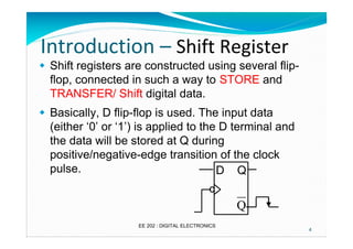


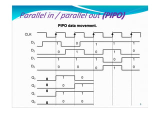


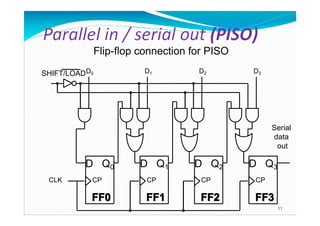

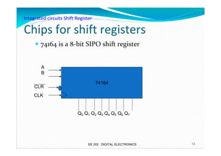

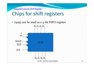
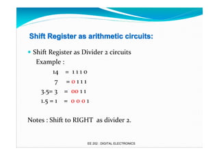
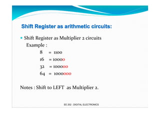
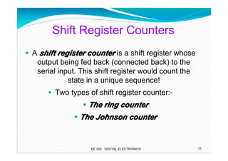
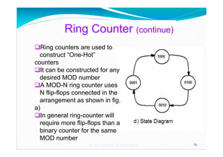


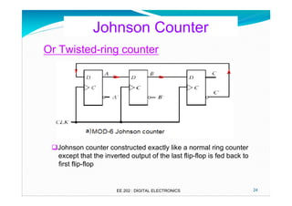
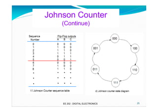


This document provides an overview of registers and shift registers. It defines four types of shift registers based on data input/output: serial in parallel out (SIPO), parallel in serial out (PISO), serial in serial out (SISO), and parallel in parallel out (PIPO). Common integrated circuit shift registers like 74164 and 74195 are described. Applications of shift registers in arithmetic operations and counters like ring counters and Johnson counters are explained. Upon completing this chapter, students should understand registers, shift register types, their operations and applications.


![SEQUENTIAL CIRCUITS [Flip-flops and Latches]](https://cdn.slidesharecdn.com/ss_thumbnails/sequentialcircuits-211217082412-thumbnail.jpg?width=640&height=640&fit=bounds)