Downloaded 157 times
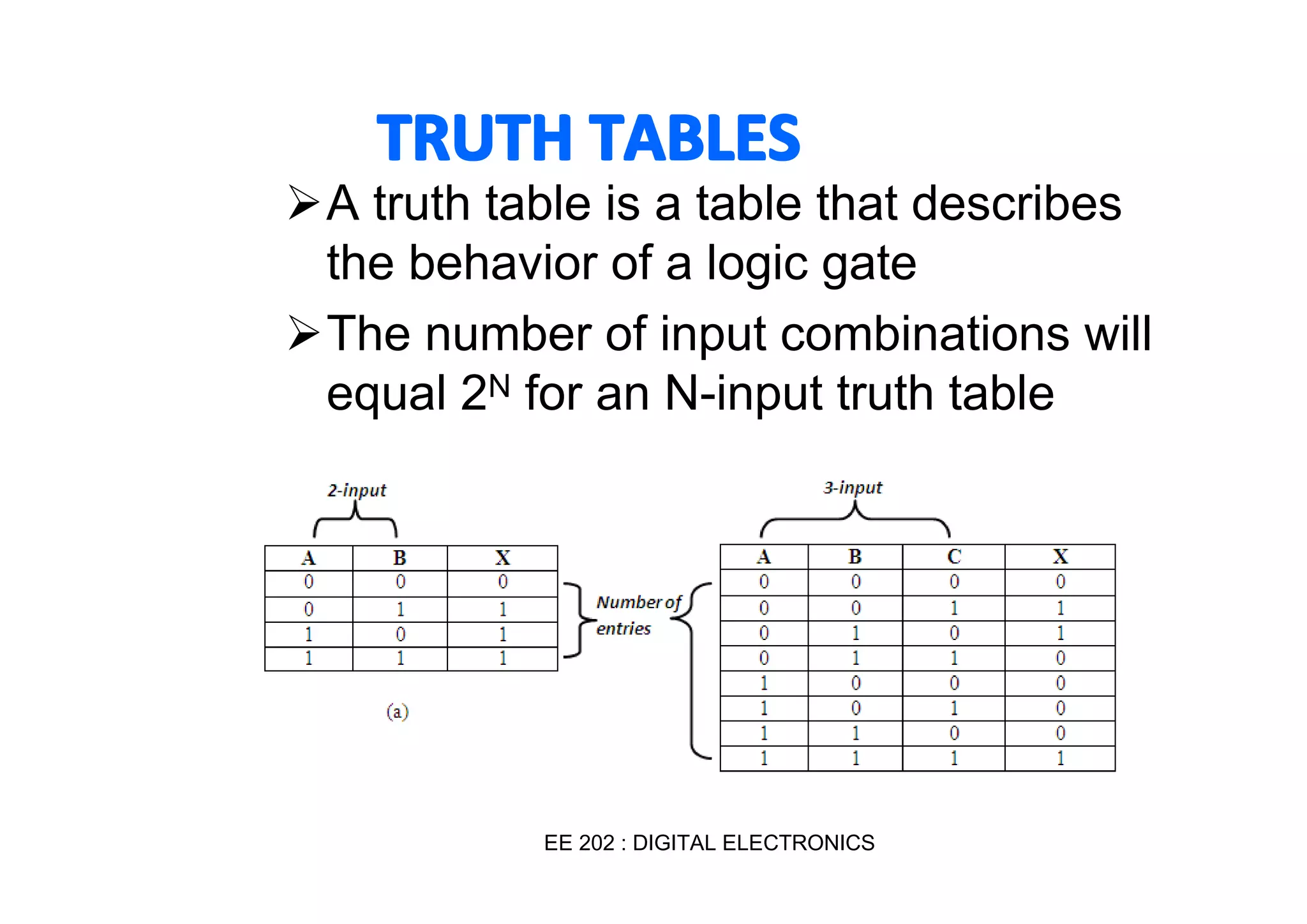
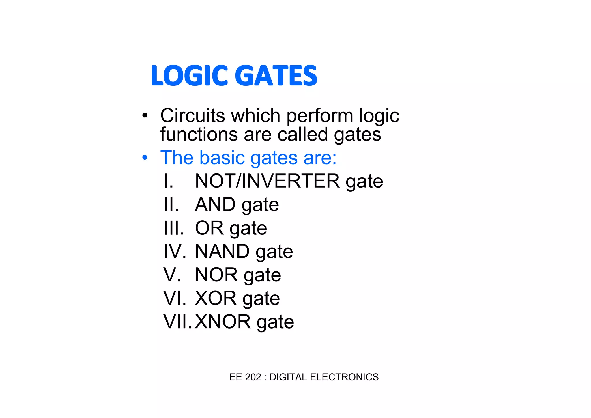
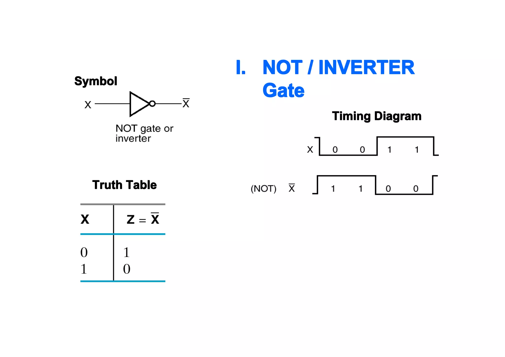
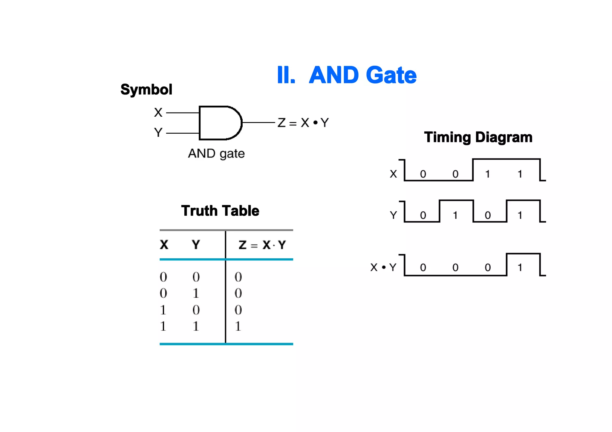
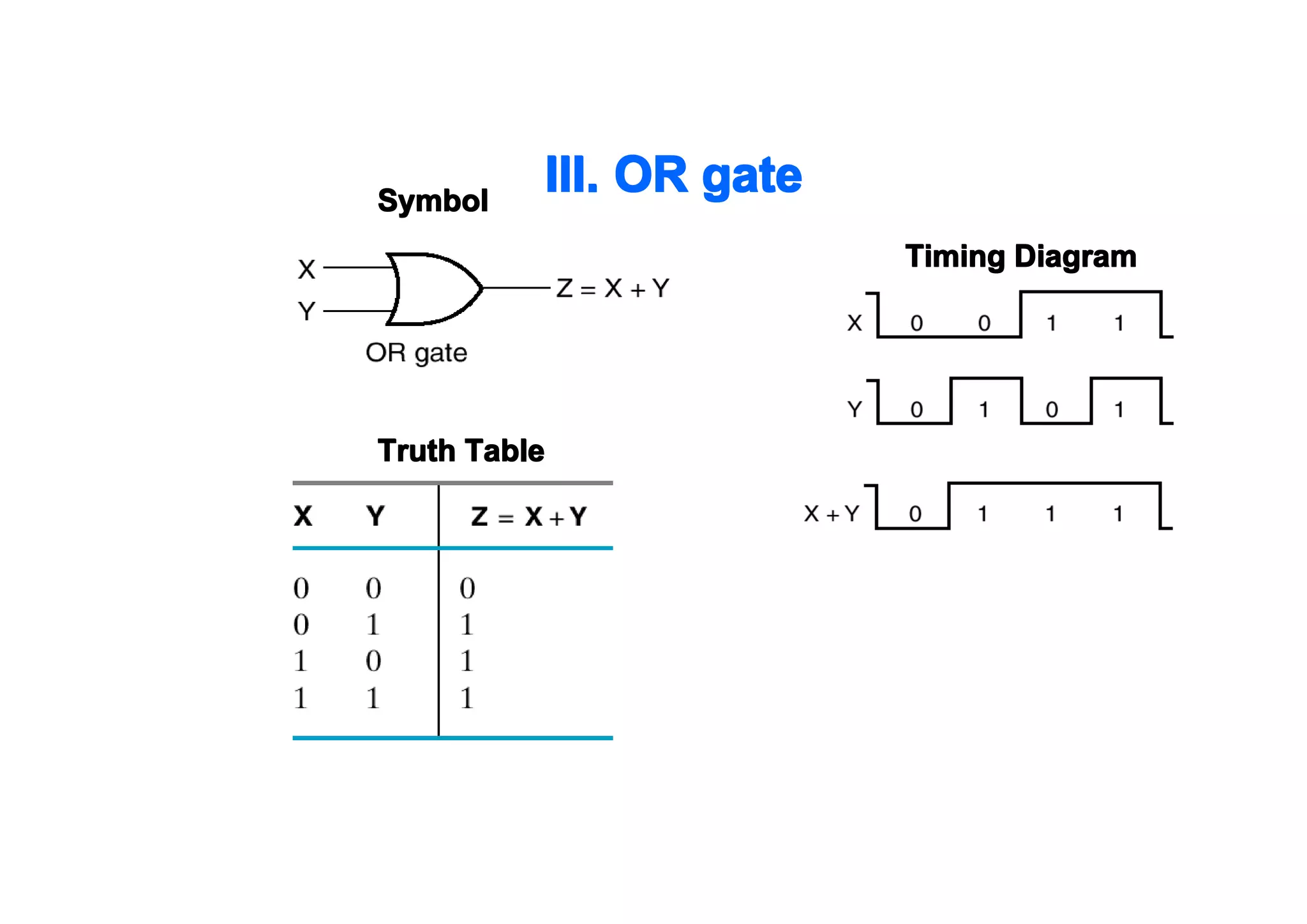
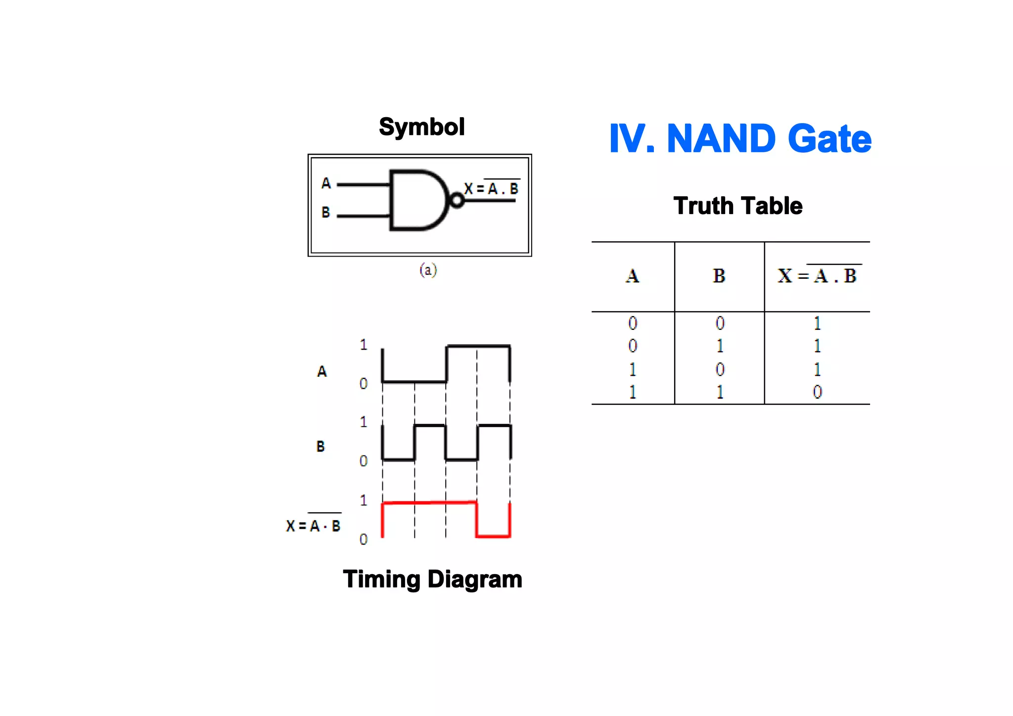
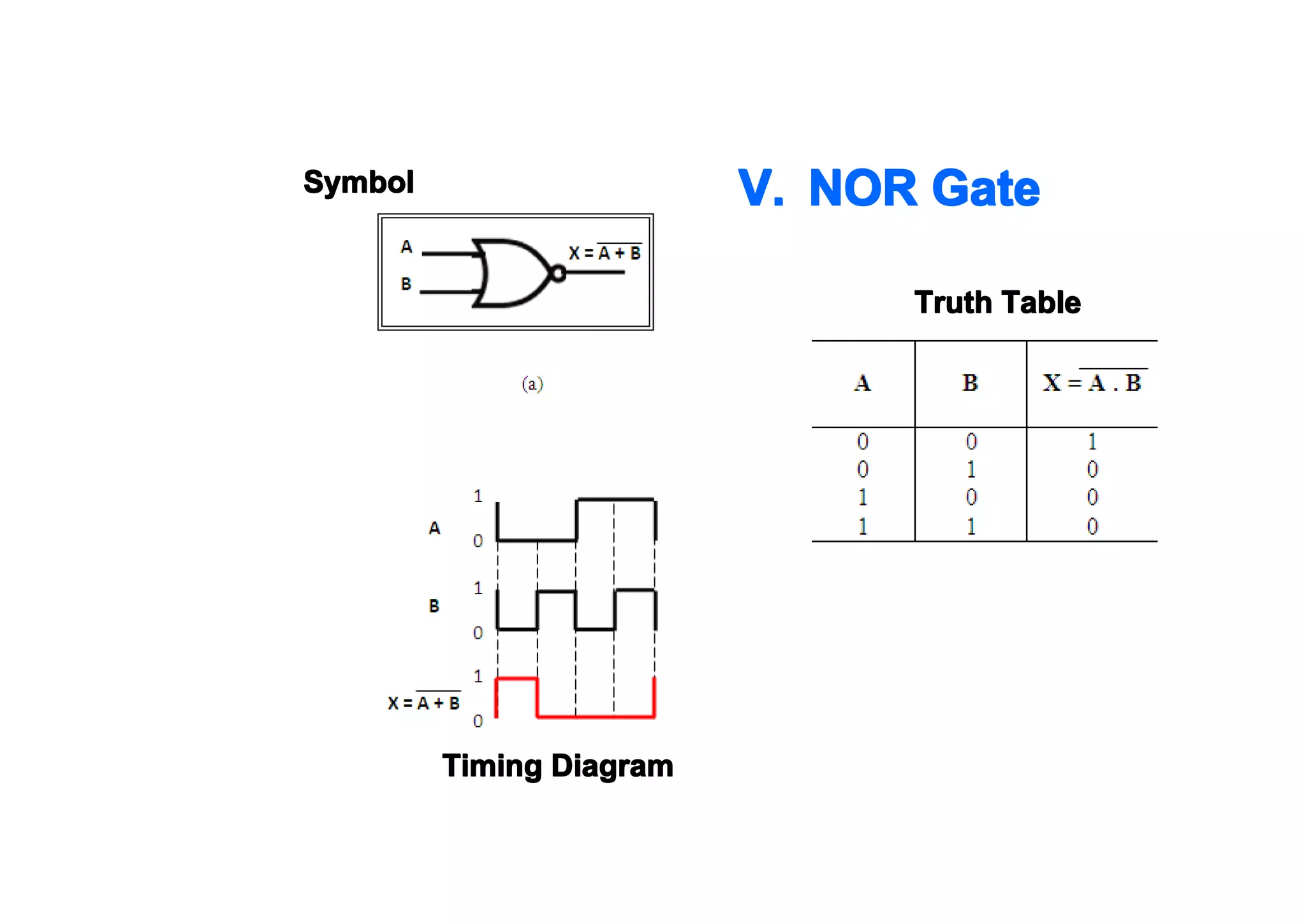
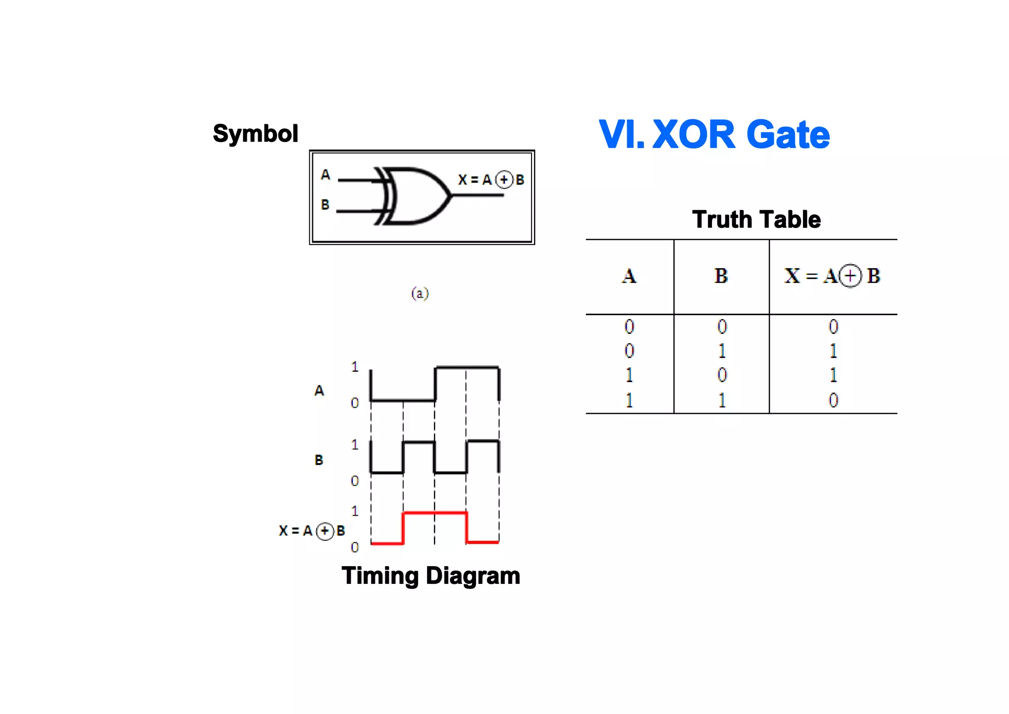
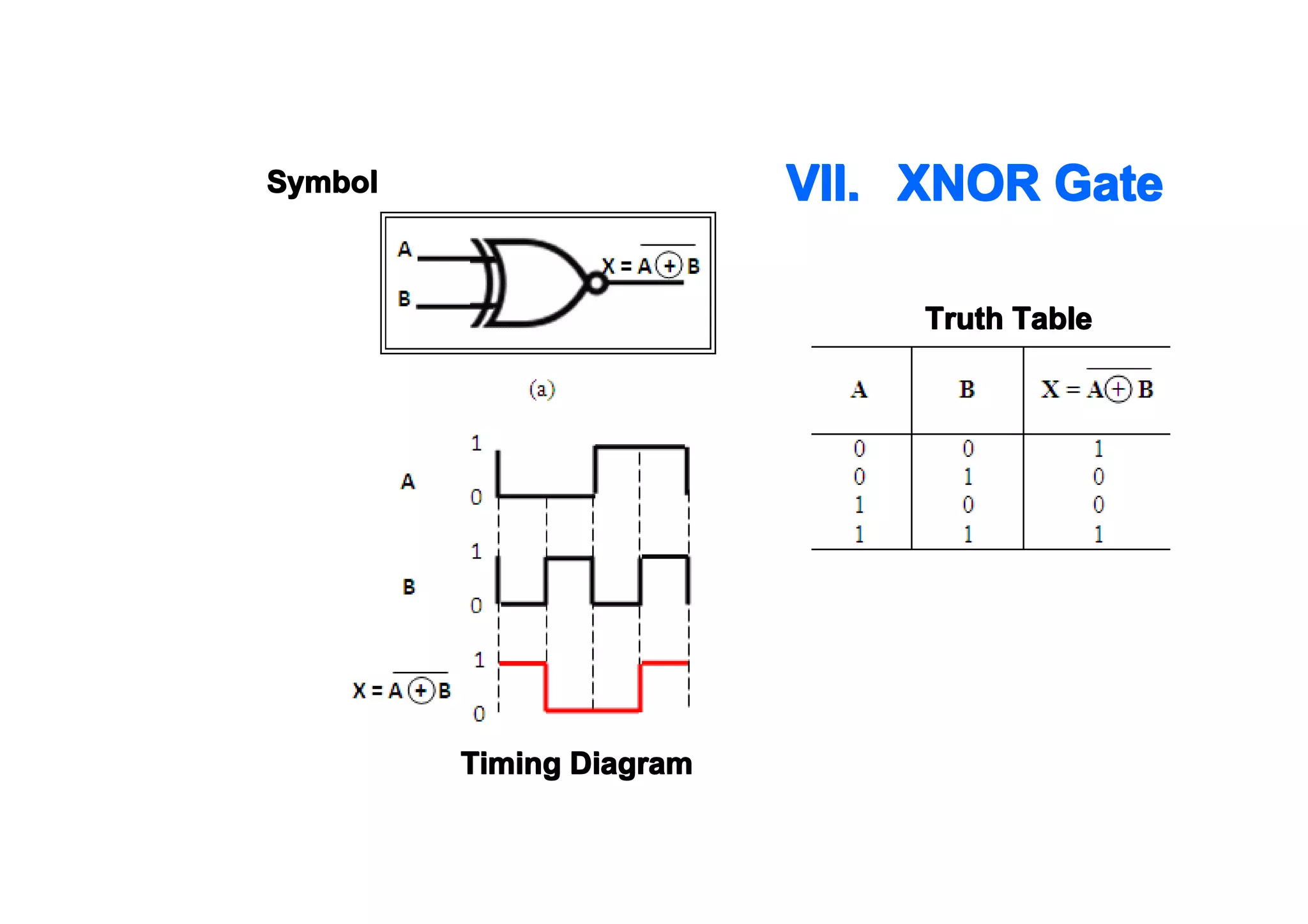
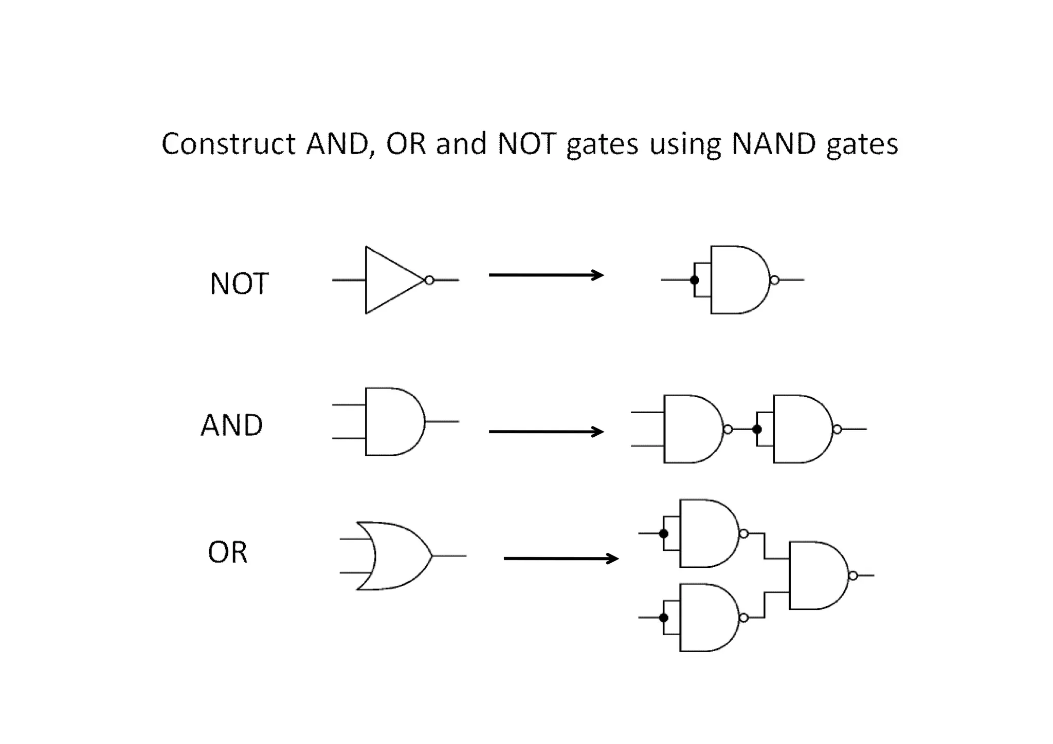
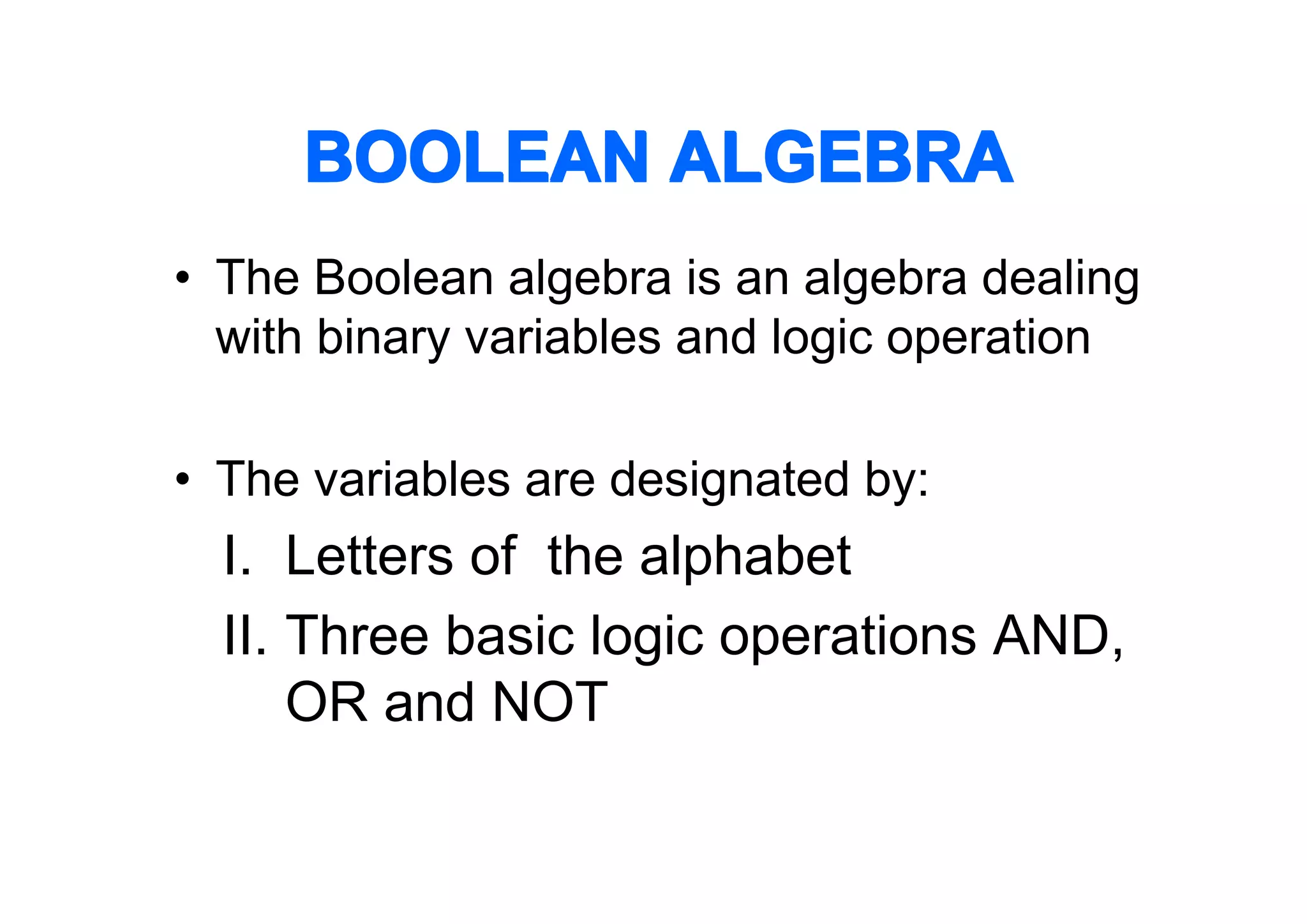
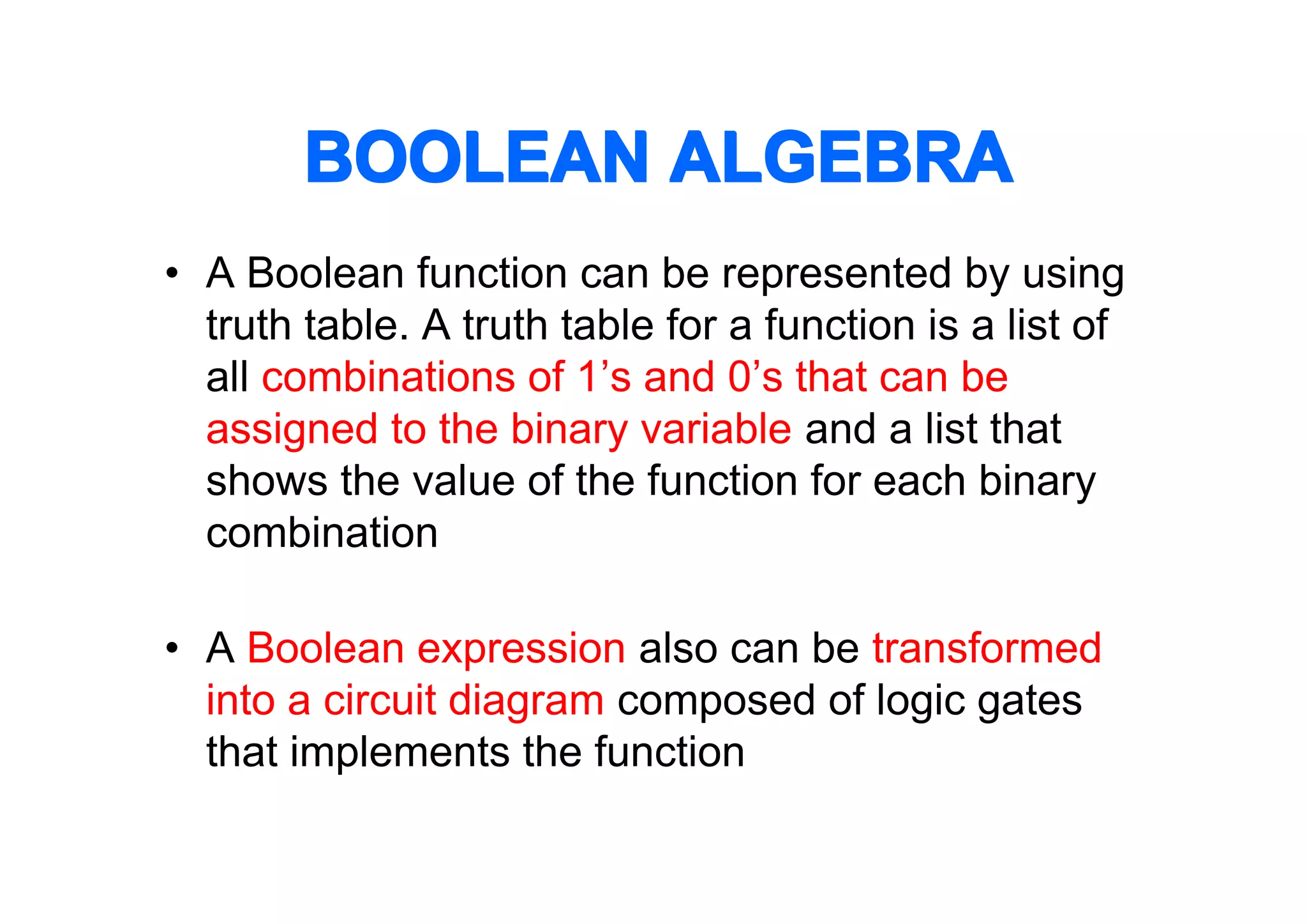
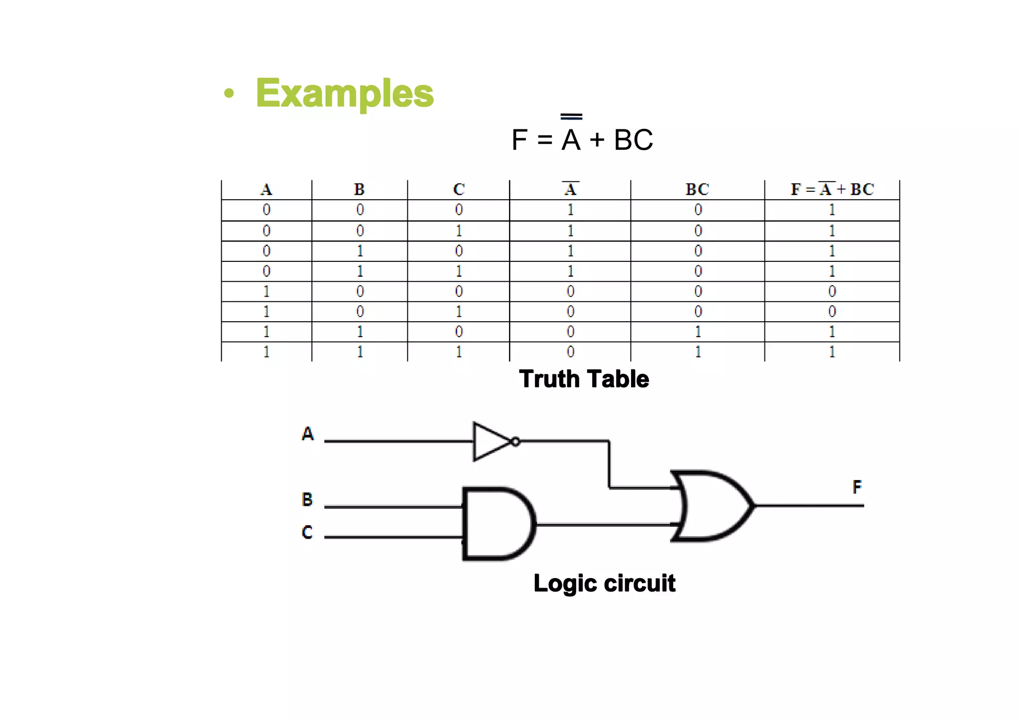
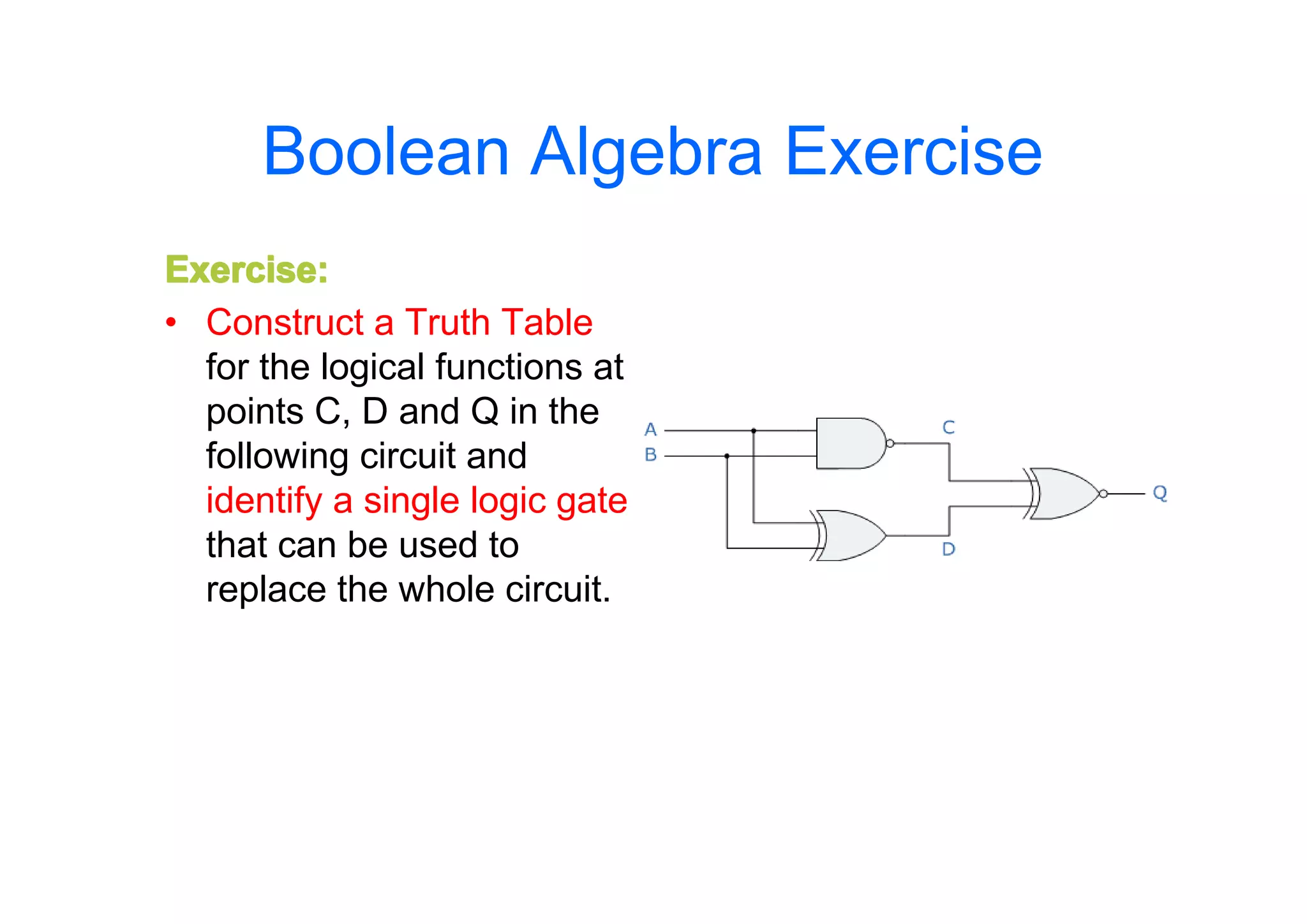
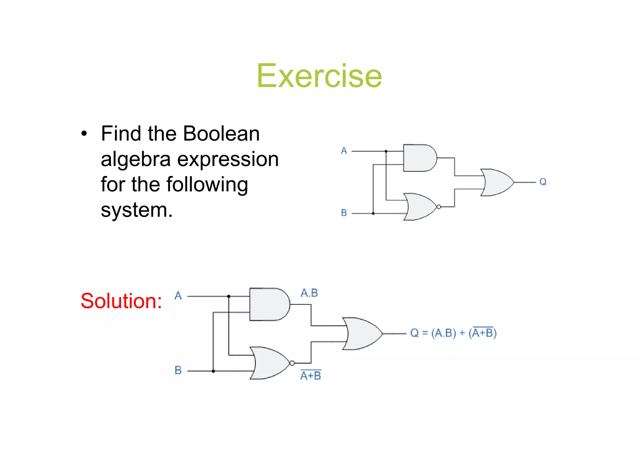
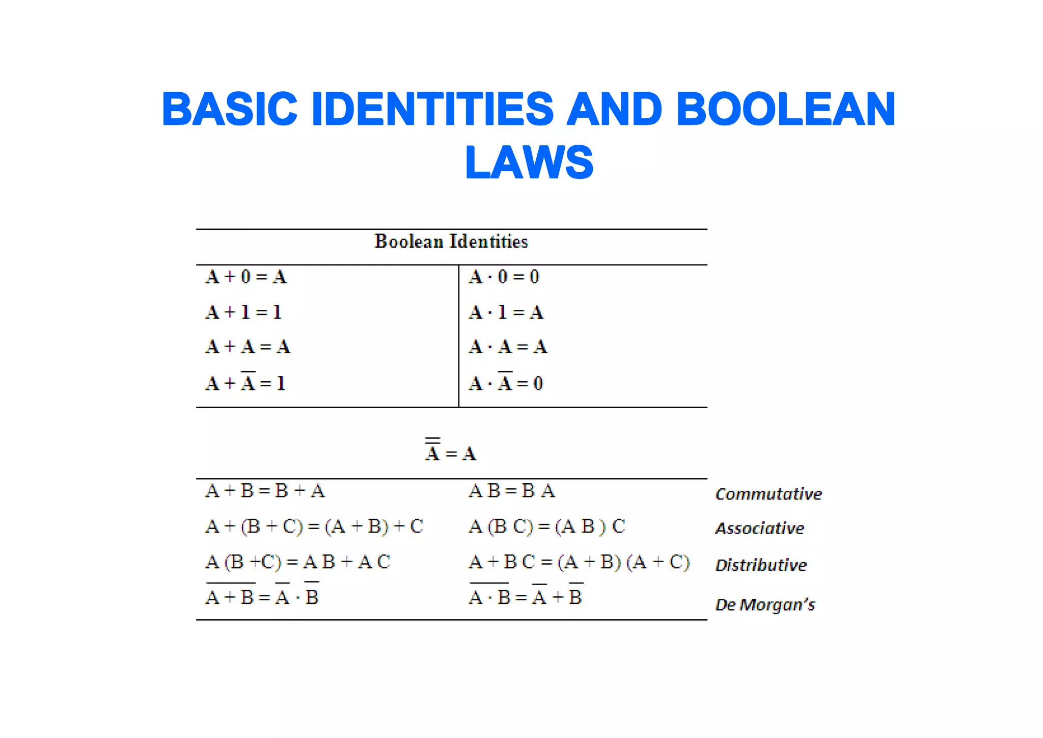
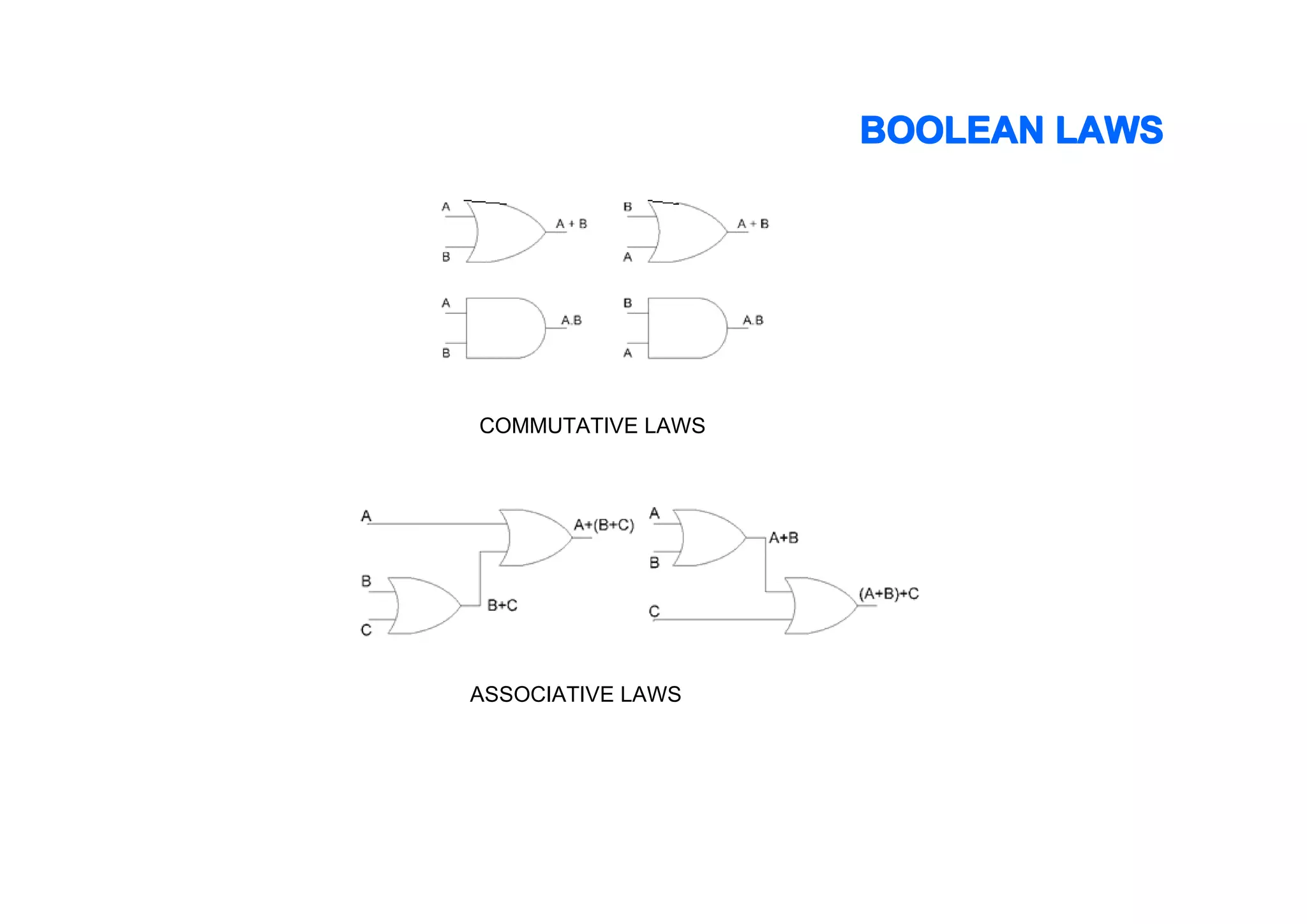
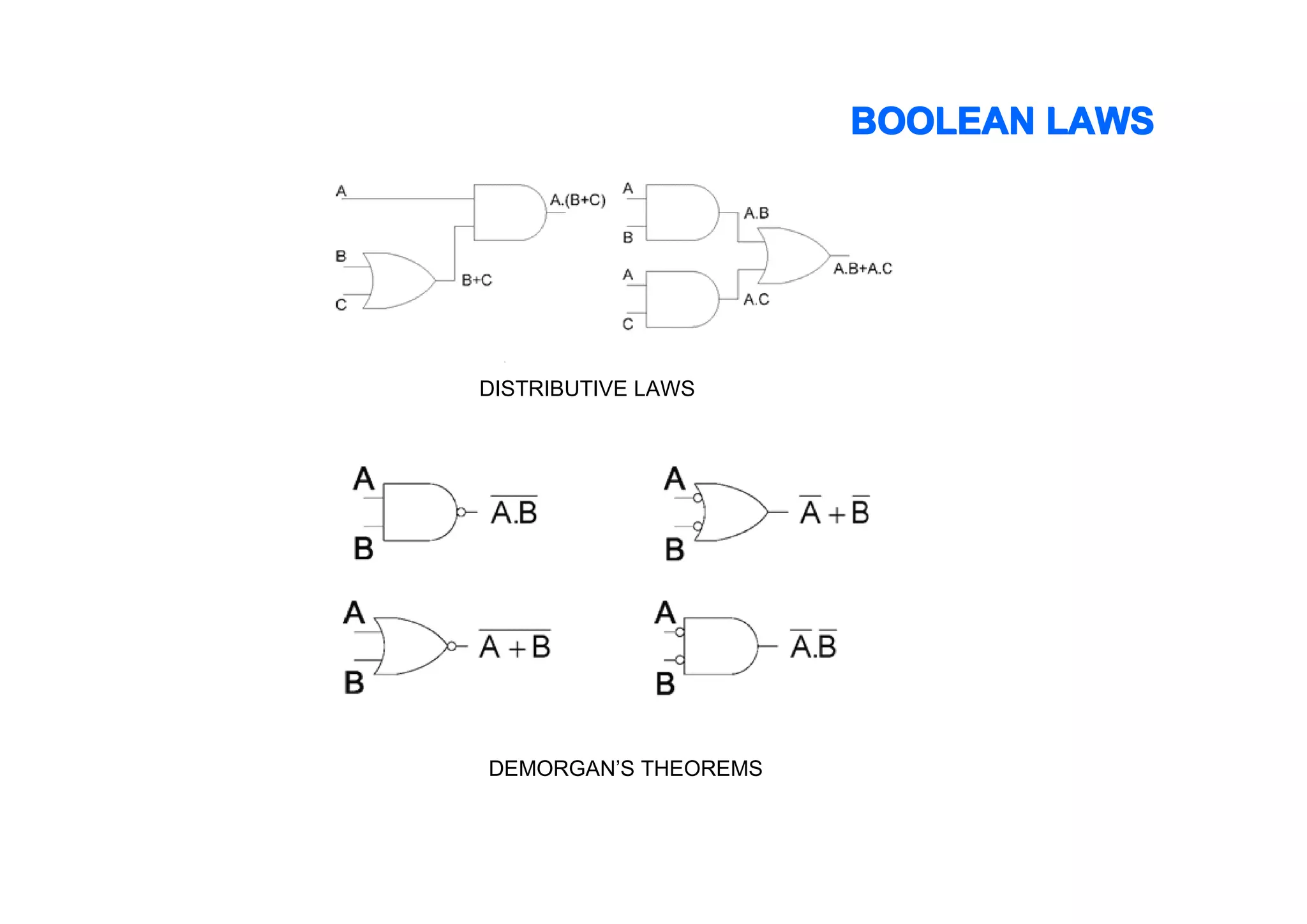
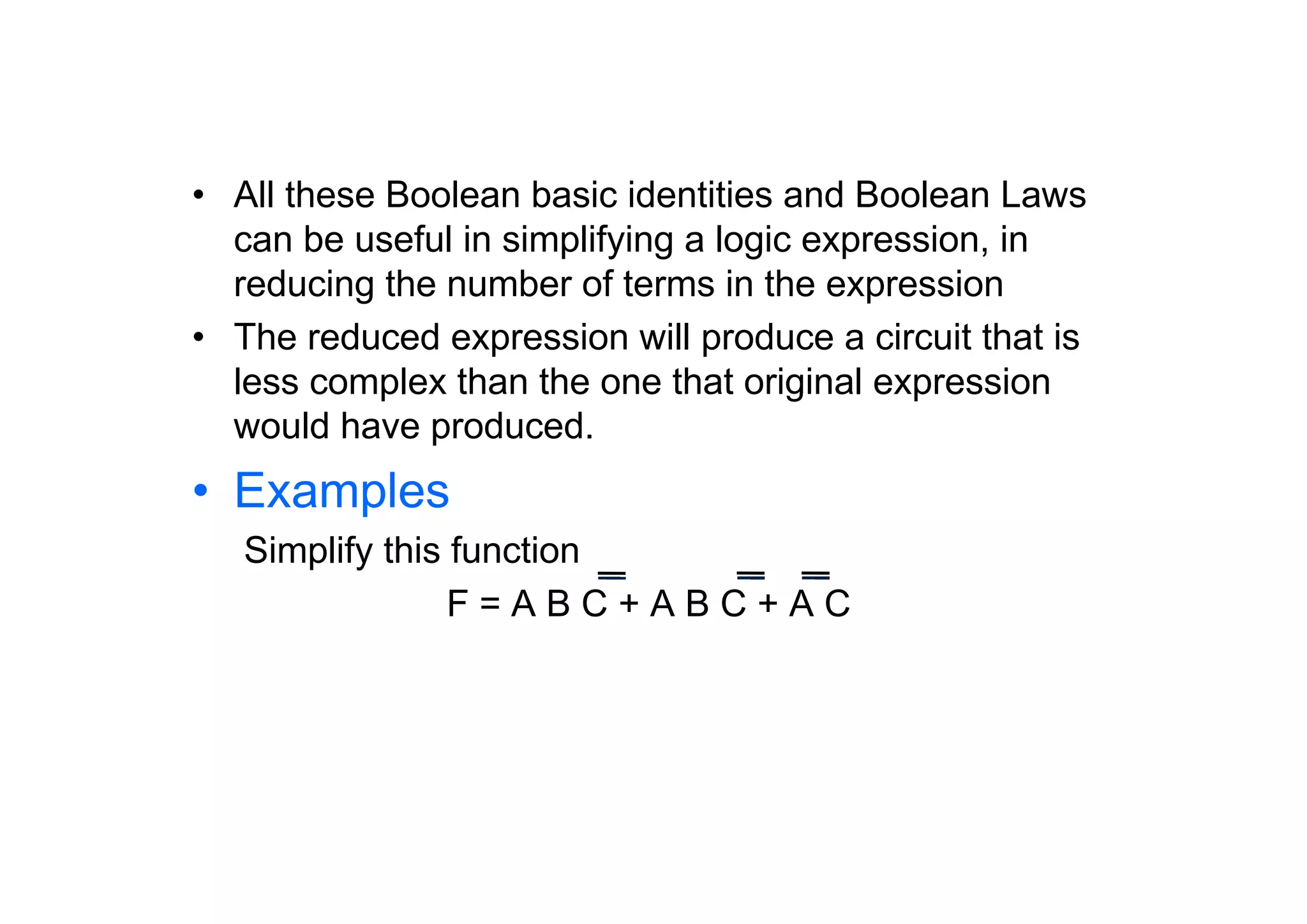
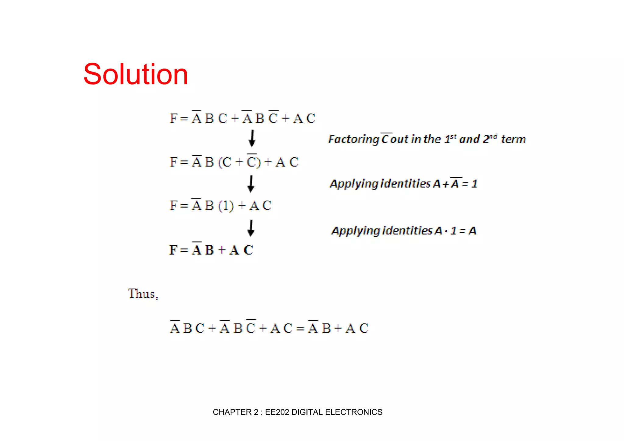
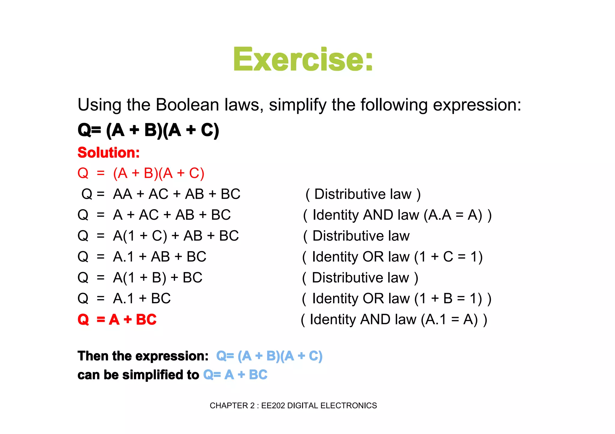

This document summarizes key topics from Chapter 2 of the course EE 202 Digital Electronics. It introduces Boolean operations including logic gates, truth tables, Boolean algebra, and Boolean laws. Logic gates such as AND, OR, NAND, and NOR are explained with their symbols, timing diagrams, and truth tables. Boolean algebra represents logical functions using variables and the operations of AND, OR, and NOT. Boolean laws like commutative, associative, distributive, and DeMorgan's theorems are presented to simplify logical expressions. Examples are provided to demonstrate applying these concepts to analyze and design combinational logic circuits.