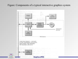
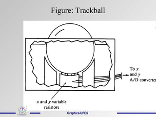
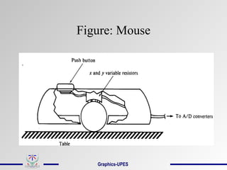
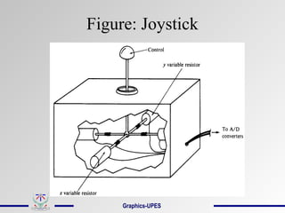
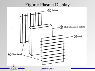
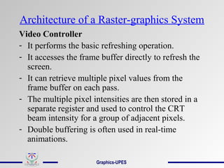
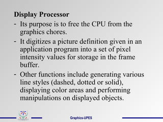
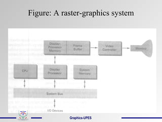
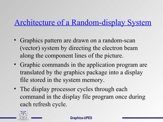
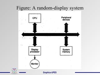
This document discusses graphics hardware components. It describes various graphics input devices like the mouse, joystick, light pen etc. and how they are either analog or digital. It then covers common graphics output devices such as CRT displays, plasma displays, LCDs and 3D viewing systems. It provides details on the internal components and working of CRT displays. It also discusses graphics storage formats and the architecture of raster and random graphics systems.
Devices that output hard copy
An external hardware device responsible for taking computer data and generating a hard copy of that data. Printers are one of the most commonly used peripherals and they print text and still images on the paper.
Impact printers use a device to strike an inked ribbon, pressing ink from the ribbon onto the paper.
Non-impact printers use different methods to place ink (or another substance) on the page.
(1) DPI:
It is a measurement of printer’s resolution indicating how many ink dots can be placed by the printer in one square inch. The higher the DPI, the sharper is image. Image quality – Measured in dots per inch (dpi). Most printers produce 300 – 1200 dpi.
(2) Type of printer:
Each type of printer has its own capabilities of printing. Some types of printers produce high quality print while other produce low quality print.
(3) Print Mode:
The printing mode may also affect the quality. For example the draft mode increases the print rate but quality is reduced.
(4) Toner:
The quality and amount of toner also affects print quality.
This includes different line drawing algorithms,circle,ellipse generating algorithms, filled area primitives,flood fill ,boundary fill algorithms,raster scan fill approaches.
Computer Graphics and its applications, Elements of a Graphics, Graphics Systems: Video Display Devices, Raster Scan Systems, Random Scan Systems, Input devices.
: Introduction of Rendering, Raytracing, Antialiasing, Fractals
Computer graphics - colour crt and flat-panel displaysVishnupriya T H
CRT monitors displays colour pictures by using a combination of phosphors that emit different colored light.
There are two types - Beam penetration method and shadow mask method
Surveying is considered as one of the oldest field of Civil Engineering. As days passes we can see lot of improvements in technology. In this ppt we can able to see latest instruments used for surveying
Computer Graphics is an advance field in information technology and all about manipulation and rendering of images. This presentation covers all the main concepts in computer graphics including graphics algorithms.
The French Revolution, which began in 1789, was a period of radical social and political upheaval in France. It marked the decline of absolute monarchies, the rise of secular and democratic republics, and the eventual rise of Napoleon Bonaparte. This revolutionary period is crucial in understanding the transition from feudalism to modernity in Europe.
For more information, visit-www.vavaclasses.com
Students, digital devices and success - Andreas Schleicher - 27 May 2024..pptxEduSkills OECD
Andreas Schleicher presents at the OECD webinar ‘Digital devices in schools: detrimental distraction or secret to success?’ on 27 May 2024. The presentation was based on findings from PISA 2022 results and the webinar helped launch the PISA in Focus ‘Managing screen time: How to protect and equip students against distraction’ https://www.oecd-ilibrary.org/education/managing-screen-time_7c225af4-en and the OECD Education Policy Perspective ‘Students, digital devices and success’ can be found here - https://oe.cd/il/5yV
Synthetic Fiber Construction in lab .pptxPavel ( NSTU)
Synthetic fiber production is a fascinating and complex field that blends chemistry, engineering, and environmental science. By understanding these aspects, students can gain a comprehensive view of synthetic fiber production, its impact on society and the environment, and the potential for future innovations. Synthetic fibers play a crucial role in modern society, impacting various aspects of daily life, industry, and the environment. ynthetic fibers are integral to modern life, offering a range of benefits from cost-effectiveness and versatility to innovative applications and performance characteristics. While they pose environmental challenges, ongoing research and development aim to create more sustainable and eco-friendly alternatives. Understanding the importance of synthetic fibers helps in appreciating their role in the economy, industry, and daily life, while also emphasizing the need for sustainable practices and innovation.
The Art Pastor's Guide to Sabbath | Steve ThomasonSteve Thomason
What is the purpose of the Sabbath Law in the Torah. It is interesting to compare how the context of the law shifts from Exodus to Deuteronomy. Who gets to rest, and why?
Operation “Blue Star” is the only event in the history of Independent India where the state went into war with its own people. Even after about 40 years it is not clear if it was culmination of states anger over people of the region, a political game of power or start of dictatorial chapter in the democratic setup.
The people of Punjab felt alienated from main stream due to denial of their just demands during a long democratic struggle since independence. As it happen all over the word, it led to militant struggle with great loss of lives of military, police and civilian personnel. Killing of Indira Gandhi and massacre of innocent Sikhs in Delhi and other India cities was also associated with this movement.
We all have good and bad thoughts from time to time and situation to situation. We are bombarded daily with spiraling thoughts(both negative and positive) creating all-consuming feel , making us difficult to manage with associated suffering. Good thoughts are like our Mob Signal (Positive thought) amidst noise(negative thought) in the atmosphere. Negative thoughts like noise outweigh positive thoughts. These thoughts often create unwanted confusion, trouble, stress and frustration in our mind as well as chaos in our physical world. Negative thoughts are also known as “distorted thinking”.
Instructions for Submissions thorugh G- Classroom.pptxJheel Barad
This presentation provides a briefing on how to upload submissions and documents in Google Classroom. It was prepared as part of an orientation for new Sainik School in-service teacher trainees. As a training officer, my goal is to ensure that you are comfortable and proficient with this essential tool for managing assignments and fostering student engagement.
How to Split Bills in the Odoo 17 POS ModuleCeline George
Bills have a main role in point of sale procedure. It will help to track sales, handling payments and giving receipts to customers. Bill splitting also has an important role in POS. For example, If some friends come together for dinner and if they want to divide the bill then it is possible by POS bill splitting. This slide will show how to split bills in odoo 17 POS.
5. Graphics Input Devices
• Any device that allows information from
outside the computer to be communicated to
the computer is considered an input device.
• Understanding of various input devices is
important in order to construct high-quality
graphical user-interfaces.
• Input devices are of two basic types: analog
and digital.
Graphics-UPES
6. Commonly used Analog Input Devices
(convert a graphic system user’s movements
into changes in voltage)
• Paddle control,
• Trackball,
• Mouse, and
• Joystick
Graphics-UPES
7. Commonly used Digital Input Devices
(are actually analog devices that collect input
information in discrete form)
• Light pen,
• Magnetic pen and tablet,
• Touch Panel, and
• Keyboard
• Digitizers
• Image Scanners
Graphics-UPES
8. Paddle Control
• Simplest of the analog input devices.
• The paddle control varies its resistance,
thereby changing the voltage of the input
circuit in relation to the movement of the
paddle’s control knob.
• Commonly, two paddle controls are used in
graphics system, one to control movement
in the x-direction and one to control
movement in the y-direction.
Graphics-UPES
10. Trackball
• Trackball is normally operated by rolling
the ball with the palm of the hand.
• It mechanically combines two variable
resistors in a single device, thus allowing
the user to use one hand to enter both x and
y information with a single device.
Graphics-UPES
12. Mouse
• The mouse, like trackball, combines two variable
resistors in a single device.
• Wheels or rollers on the bottom of the mouse can
be used to record the amount and direction of
movement. Another method for detecting mouse
motion is with an optical sensor.
• One, two or three buttons are usually included on
the top of the mouse for signaling the execution of
some operation, such as recording cursor position
or invoking a function.
Graphics-UPES
14. Joystick
• A joystick consists of a small, vertical lever
(stick) mounted on a base that is used to
steer the screen cursor around.
• The distance that the stick is moved in any
direction from its center position
corresponds to screen-cursor movement in
that direction.
Graphics-UPES
16. Light Pen
• Light pens are used to select screen
positions by detecting the light coming from
the points on the CRT screen.
• They are sensitive to the short burst of light
emitted from the phosphor coating at the
instant the electron beam strikes a particular
point.
• The recorded light-pen coordinates can be
used to position an object or to select a
processing option.
Graphics-UPES
18. Magnetic pen and tablet
• A magnetic pen and tablet are composed of
a two-dimensional wire grid and a
radiowave-emitting stylus.
• The wire grid is a matrix antenna which
locates the position of the stylus measuring
the intensity of the radio signal received by
each wire in the grid.
Graphics-UPES
20. Touch Panel
• Touch panels allow displayed objects or
screen positions to be selected with the
touch of a finger.
• Optical touch panels make use of a series of
infrared light-emitting diodes (LEDs) and
sensors located around the perimeter of the
display.
• When the user touches the screen, light
beams are broken, indicating the location of
the user’s finger.
Graphics-UPES
22. Keyboard
• The keyboard is an efficient device for inputting
nongraphic data as picture levels associated with a
graphic display.
• Keyboards can also be provided with features to
facilitate entry of screen coordinates, menu
selections, or graphic functions.
• Function keys allow users to enter frequently used
operations in a single keystroke, and cursor-
control keys can be used to select displayed
objects or coordinate positions by positioning the
screen cursor.
Graphics-UPES
24. Digitizers
• A common device for interactively
selecting coordinate positions on a object is
a digitizer.
• These discrete coordinate positions can be
joined with straight-line segments to
approximate the curve or surface shapes.
• Graphic tablets provide a highly accurate
method for selecting coordinate positions
with accuracy of about 0.05 mm.
Graphics-UPES
25. Digitizers
• Many graphic tablets are constructed with a
rectangular grid of wires embedded in the
tablet surface.
• Electromagnetic pulses are generated in
sequence along the wires, and an electric
signal is induced in a wire coil in an
activated stylus or hand cursor to record a
tablet position.
Contd…
Graphics-UPES
27. Image Scanners
• An image scanner records the gradations of
gray scale/color of a given color or b/w
photos and stores in an array.
• On stores image, we can apply
transformations to rotate, scale, crop the
picture to a particular screen area.
• We can also apply various image
processing methods to modify the array
representation of the picture (e.g. contrast
enhancement).
Graphics-UPES
29. DataGlove: 3D Interaction Device
• The glove is constructed with a series of
sensors that detect hand and finger
movements.
• Electromagnetic coupling between
transmitting antennas and receiving
antennas is used to provide information
about position and orientation of the hand.
• Inputs from the glove can be used to
position or manipulate objects in a virtual
scene.
Graphics-UPES
31. Graphic Storage Formats
Regardless of the storage medium selected,
the graphics system designer will always
use some combination of the following
basic storage formats:
1. Image-only Storage
2. Display-memory Storage
3. Compressed-memory Storage
4. Information Storage
Graphics-UPES
32. Image-Only Storage
• Here the video image is retained on video
tape or video disk or as a photograph.
• Storage of images in this fashion is
relatively inexpensive.
• Once the image is stored, it is difficult and
expensive to restore it to the computer for
further manipulation.
Graphics-UPES
33. Display-Memory Storage
• Here the bit pattern that represents the
image is copied directly from display
memory to the storage medium.
• A utility program may be used to save
blocks of the computer memory by passing
the starting and ending addresses of the
display memory.
• Drawback: Storing images in this manner
requires a great deal of memory.
Graphics-UPES
34. Compressed-Memory Storage
• Storage space can be greatly reduced by
storing images in compressed format.
• Compression takes advantage of repeated
patterns in display memory.
• Compression routines can be very complex,
taking advantage of long series of
replication.
• It may not be useful when images to be
saved contain no or few series of replicated
bytes.
Graphics-UPES
36. Information Storage
• It retains the information (series of
commands that describe the image) used to
construct the image.
• It can save considerable time and memory if
the image to be stored is composed entirely
of standard objects.
• This approach is not fruitful if nonstandard
objects are used.
Graphics-UPES
39. Graphics Output Devices
• Most commonly used computer output
devices that are capable of producing
graphical output are:
Raster-scan Cathode Ray Tube (CRT)
Plasma Display
Liquid Crystal Display
3D Viewing using Stereoscopic Systems
Plotters and Printers
Graphics-UPES
40. Raster-Scan CRT
• Interactive computer graphics demands display
devices whose images can be changed quickly.
• Nonpermanent image displays allow an image to
be changed, making possible dynamic movement
of portions of an image.
• Raster-scan CRTs are used in common television
sets. The term “raster” is synonym for the term
“matrix”. A raster-scan CRT scans a matrix with
an electron beam.
• The basic understanding of CRT’s internal
operations is useful in graphics programming.
41. Components of a raster-scan CRT
• Electron gun
• Control electrode
• Focusing electrode
• Deflection yoke
• Phosphorus-coated screen
Graphics-UPES
43. Electron Gun
• It consists of a series of components
(primarily a heater and a cathode) which
together cause electrons to collect at the end
of the electron gun.
• These electrons are then accelerated by
application of an electric field.
Graphics-UPES
44. Control Electrode
• It is used to regulate the flow of electrons.
• It is a metal cylinder that fits over the
cathode.
• A negative voltage on the control electrode
simply decreases the number of electrons
passing through.
• Hence intensity of the electron beam is
controlled by setting voltage levels on the
control electrode.
Graphics-UPES
45. Focusing Electrode
• It is used to create a clear picture by
focusing the electron beam into a narrow
beam.
• The focusing electrode serves this purpose
by extracting an electromagnetic force on
the electrons in the electron beam.
• The effect resembles that of a glass lens on
light wave.
Graphics-UPES
46. Deflection Yoke
• It is used to control the direction of the
electron beam.
• The deflection yoke creates a magnetic field
which will bend the electron beam as it
passes through the field.
• In a conventional CRT the yoke is
connected to a scan generator.
Graphics-UPES
47. • The scan generator sends out an oscillating
sawtooth current that, in turn, causes the
deflection yoke to apply a varying magnetic
field to the electron beam’s path.
• The oscillating voltage potential causes the
electron beam to move across the CRT’s
screen in a regular pattern.
Graphics-UPES
48. Phosphorus-coated Screen
• The CRT surface is coated with special crystals
called phosphors.
• Phosphors glow when they are hit by a high-
energy electron beam.
• The glow given off by the phosphor during
exposure to the electron beam is known as
fluorescence.
• The continuing glow given off after the beam is
removed is known as phosphorescence. Its
duration is known as the phosphor’s persistence.
Graphics-UPES
49. Principle of Raster-scan Displays
• Picture definition is stored in a memory area
called the refresh buffer or frame buffer.
This memory area holds the set of intensity
values for all the screen points.
• The electron beam is swept across the
screen, one row at a time from top to bottom
and painting the stored intensity values.
Graphics-UPES
50. Refresh and Flicker
Each time the electron beam goes through a
complete cycle of rater or scan lines, the
CRT is said to be “refreshed”.
It is very important that the persistence of
the phosphor used and the refresh rate be
matched.
Otherwise, an image on the CRT may
appear to flash rapidly on and off. It is
called “flicker”.
Graphics-UPES
51. Horizontal/ Vertical Retrace
• Refreshing of rater-scan displays is done at
the rate of 60 to 80 frames per second.
• At the end of each scan line, the electron
beam returns to the left side of the screen to
begin displaying the next line (horizontal
retrace).
• And at the end of each frame, the electron
beam returns to the top left corner of the
screen to begin the next frame (vertical
retrace).
Graphics-UPES
52. Interlacing
• Interlacing is primarily used with slower
refreshing rates to avoid flicker.
• Here each frame is displayed in two passes
(so the entire screen is displayed in one-half
the time).
• In the first pass, the beam sweeps across
every other scan line from top to bottom.
• Then after the vertical retrace, the beam
sweeps out the remaining scan lines.
Graphics-UPES
54. Plasma Display
It is one of the flat-panel display under
emissive (convert electrical energy into light)
display category.
Plasma displays do not have to be refreshed;
that is, once a pixel is displayed on the
screen, it will remain lit until it is
intentionally turned off.
The electrofluorescent material is nothing but
an array of tiny neon bulbs. Each bulb can be
put into an “on” state or an “off” state, and
remains in the state until explicitly changed to
the other.
Graphics-UPES
56. Liquid Crystal Display
These non-emissive devices produce a
picture by passing polarized light from the
surroundings or from an internal light
source through a liquid crystal material that
can be aligned to either block or transmit
the light.
The Glass plate serves as a bounding
surface for the conductive coating.
Conductive coating acts as a conductor so
that a voltage can be applied across the
liquid crystal.
Graphics-UPES
57. Liquid crystal is a substance which will polarize
light when a voltage is applied to it.
Polarized film is a transparent sheet that
polarizes light. Its axis of polarization is kept
900
out of phase with that of the liquid crystal.
Figure: Liquid Crystal Display
Graphics-UPES
58. Plotters
• All plotters behave like slow vector devices
from the graphics programmer’s point of
view.
• Examples:
Flatbed plotter
Drum plotter
• Components of a Flatbed plotter:
Pen – an actual pen that draws on the paper.
Graphics-UPES
59. Write-move mechanism – used to lift and
lower the pen.
Pen cartridge – holds several different
colored pens. The plotter holds a program
in ROM that instructs to pick corresponding
color pen.
x Driver motor – moves the pen
horizontally across the paper.
y Driver motor – moves the pen vertically
across the paper.
Graphics-UPES
60. 3D Viewing using Stereoscopic Systems
• In a stereoscopic projection, two views of a
scene are generated from a viewing direction
corresponding to each eye.
• When we simultaneously look at the left
view with the left eye and the right view with
the right eye, the two views merge into a
single image and we perceive a scene with
depth.
• Examples: i) stereoscopic glasses & an
infrared synchronizing emitter, ii) Headset
Graphics-UPES
63. Architecture of a Raster-graphics System
Video Controller
- It performs the basic refreshing operation.
- It accesses the frame buffer directly to refresh the
screen.
- It can retrieve multiple pixel values from the
frame buffer on each pass.
- The multiple pixel intensities are then stored in a
separate register and used to control the CRT
beam intensity for a group of adjacent pixels.
- Double buffering is often used in real-time
animations.
Graphics-UPES
64. Display Processor
- Its purpose is to free the CPU from the
graphics chores.
- It digitizes a picture definition given in an
application program into a set of pixel
intensity values for storage in the frame
buffer.
- Other functions include generating various
line styles (dashed, dotted or solid),
displaying color areas and performing
manipulations on displayed objects.
Graphics-UPES
66. Architecture of a Random-display System
• Graphics pattern are drawn on a random-scan
(vector) system by directing the electron beam
along the component lines of the picture.
• Graphic commands in the application program are
translated by the graphics package into a display
file stored in the system memory.
• The display processor cycles through each
command in the display file program once during
each refresh cycle.
Graphics-UPES