![ADE Module-5
Kishore Kumar R RLJIT Page 17
Program: Write Verilog code for MOD-8 down counter
module DC (CLK, PRESET, Q);
input CLK,PRESET;
output [2:0]Q;
reg [2:0]Q;
always @ (negedge clk or negedge PRESET)
If (~PRESET) Q=3’b111;
else Q=Q – 1;
endmodule
Important Questions
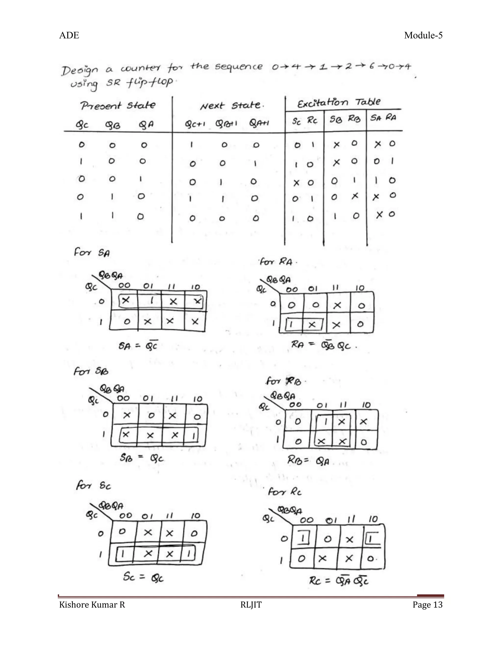
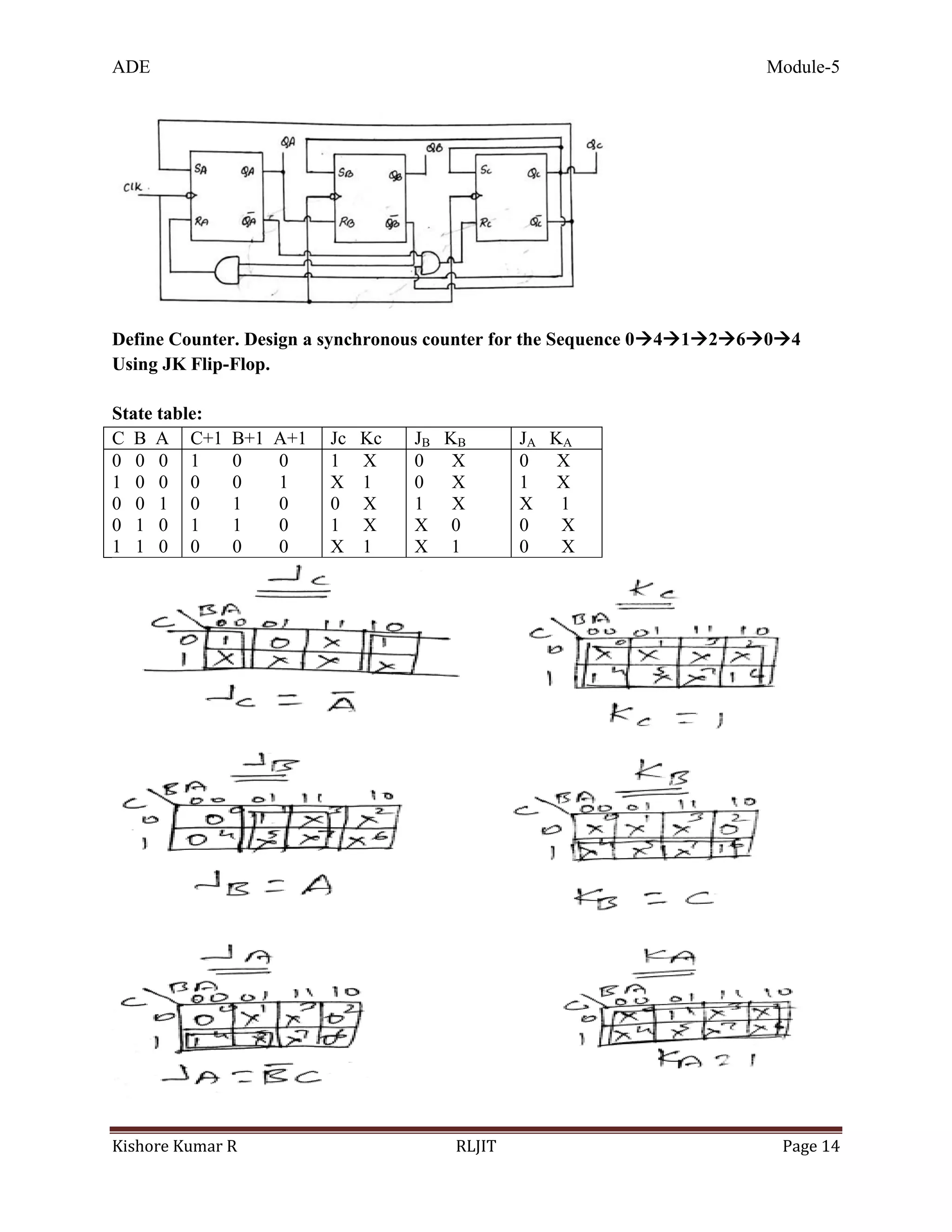
1. Define Counter. Design a synchronous counter for the sequence 0412604 using
JK Flip-Flop JAN-17 (12 M)
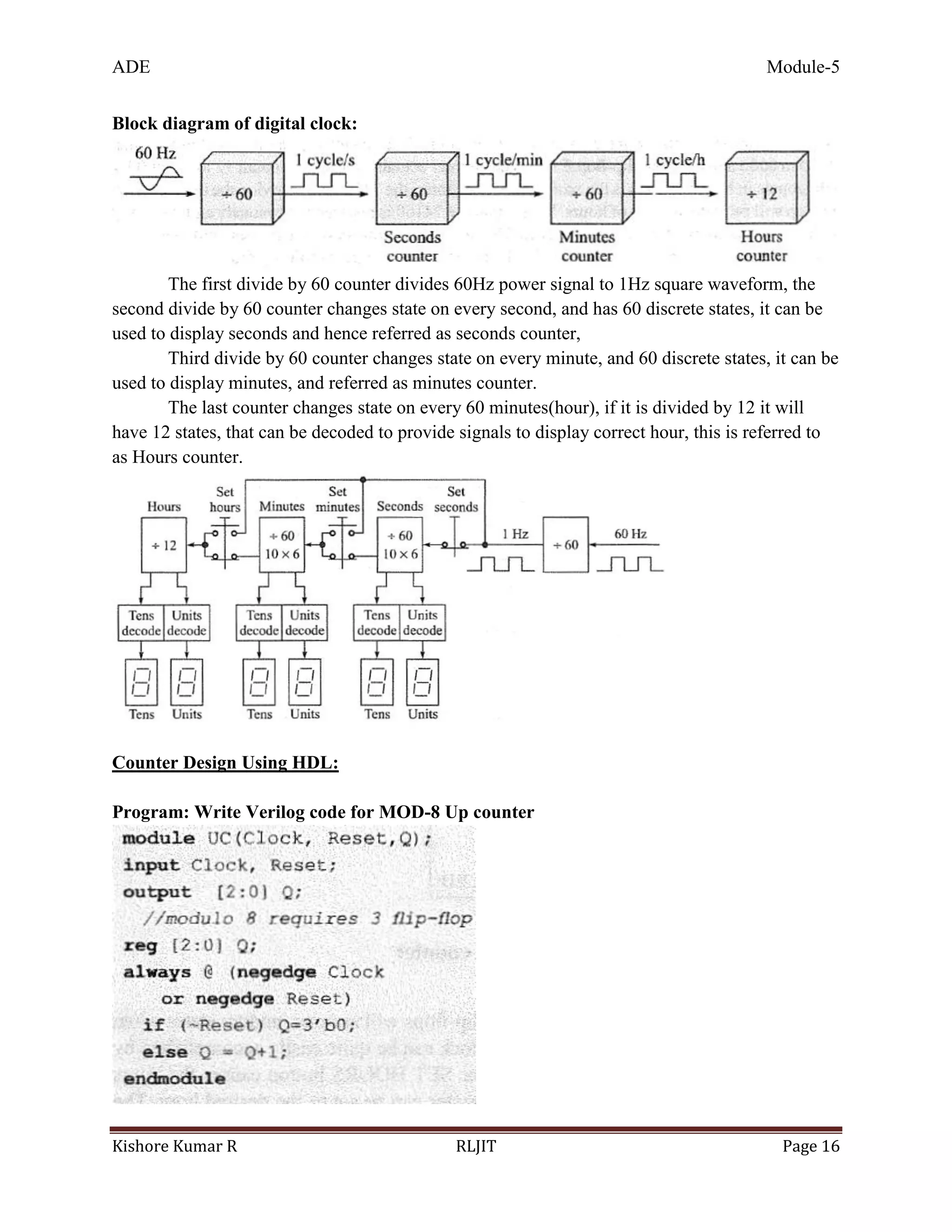
2. Explain Digital clock with neat diagram JAN&JUL-17 (4 M)
3. Define Counter. Design a synchronous counter for the sequence 0412604 using
SR Flip-Flop JUL-17 (12 M)
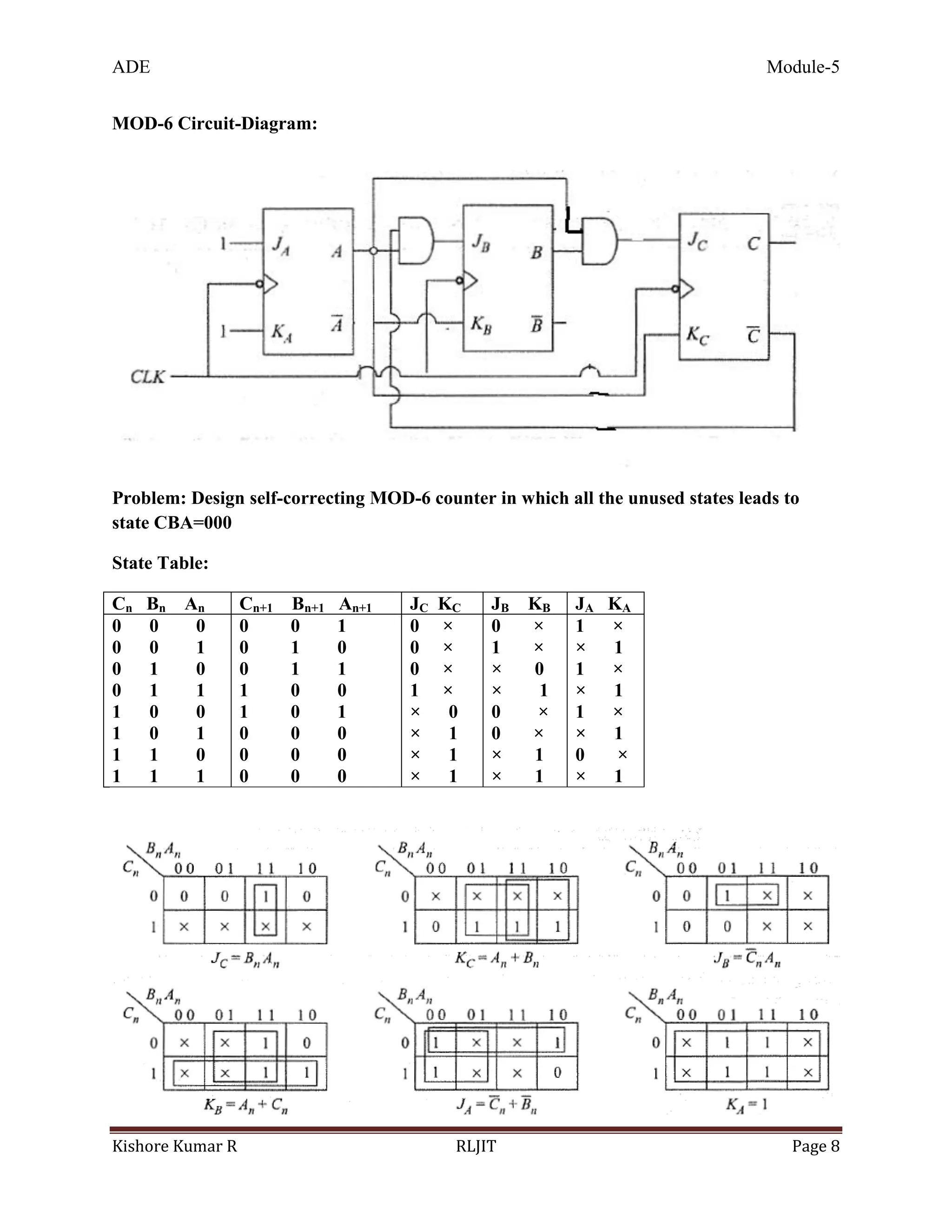
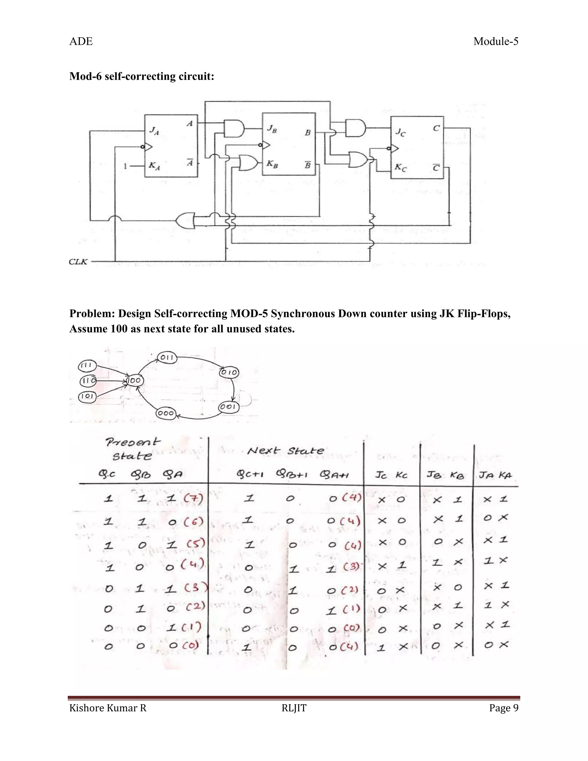
4. Design self-correcting MOD-6 Counter.
5. Explain Presettable MOD-8 counter
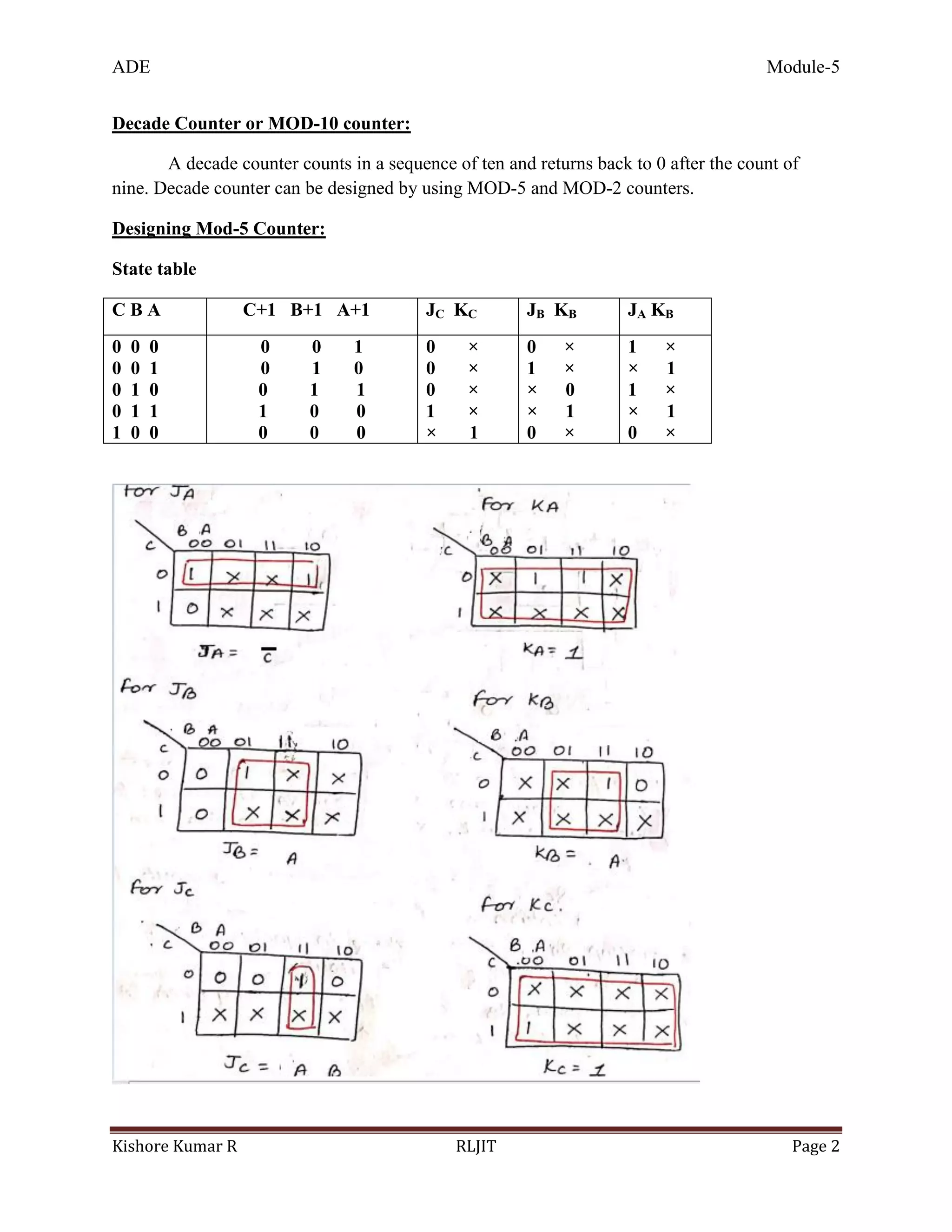
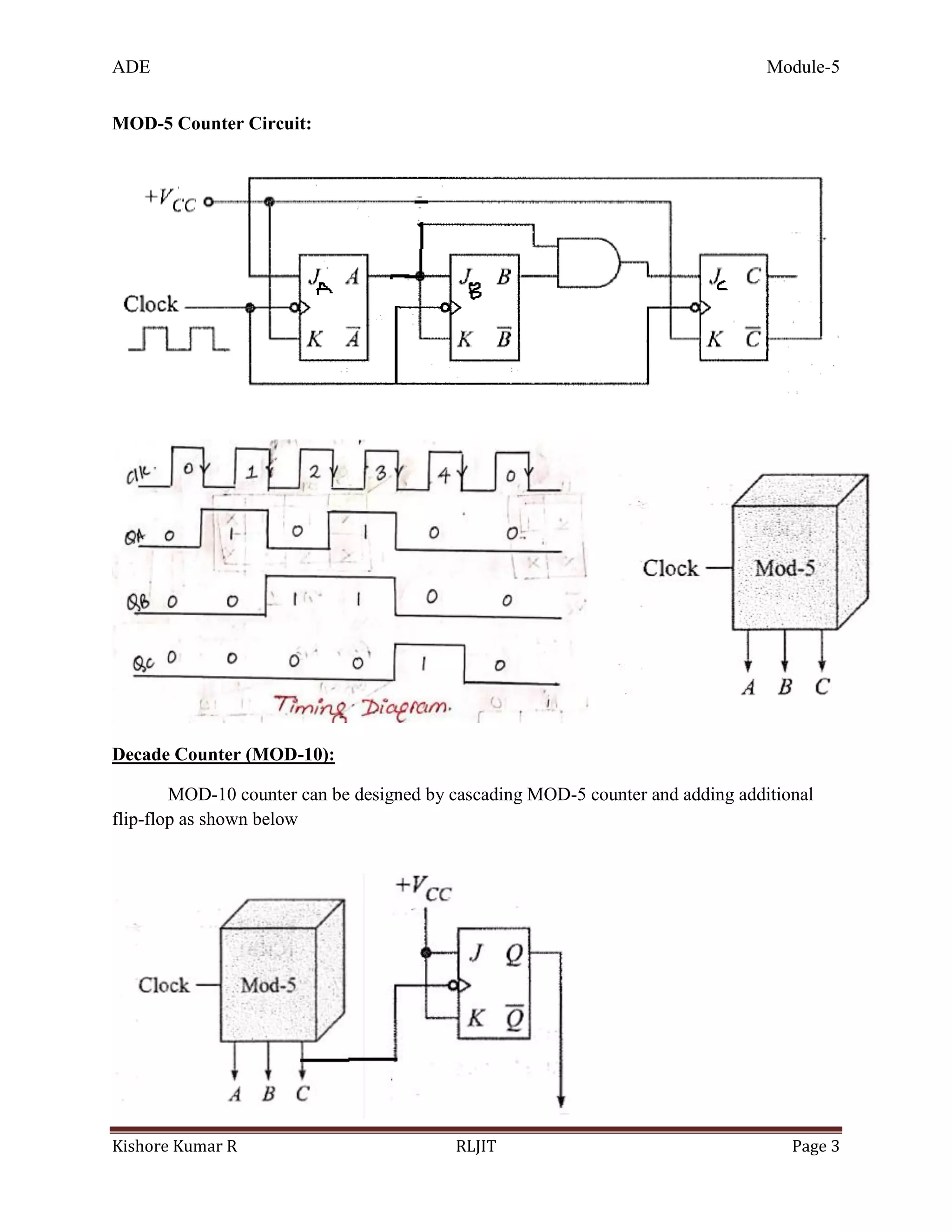
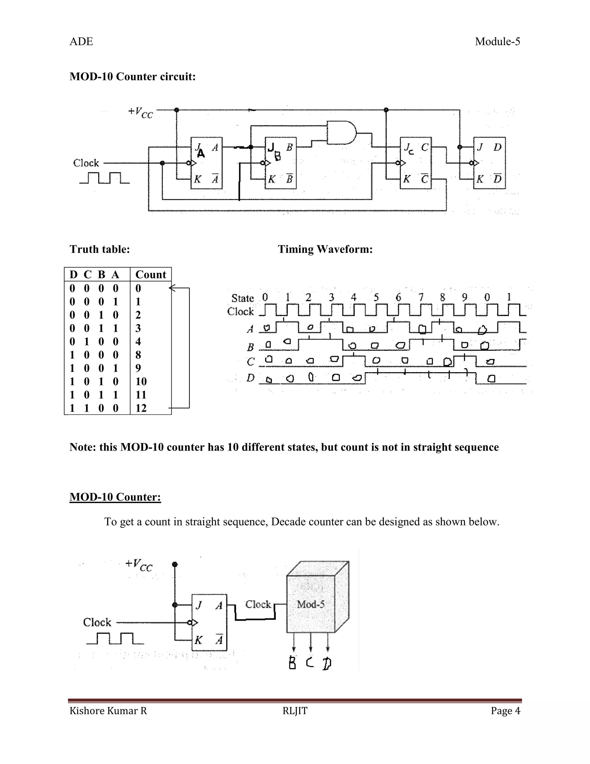
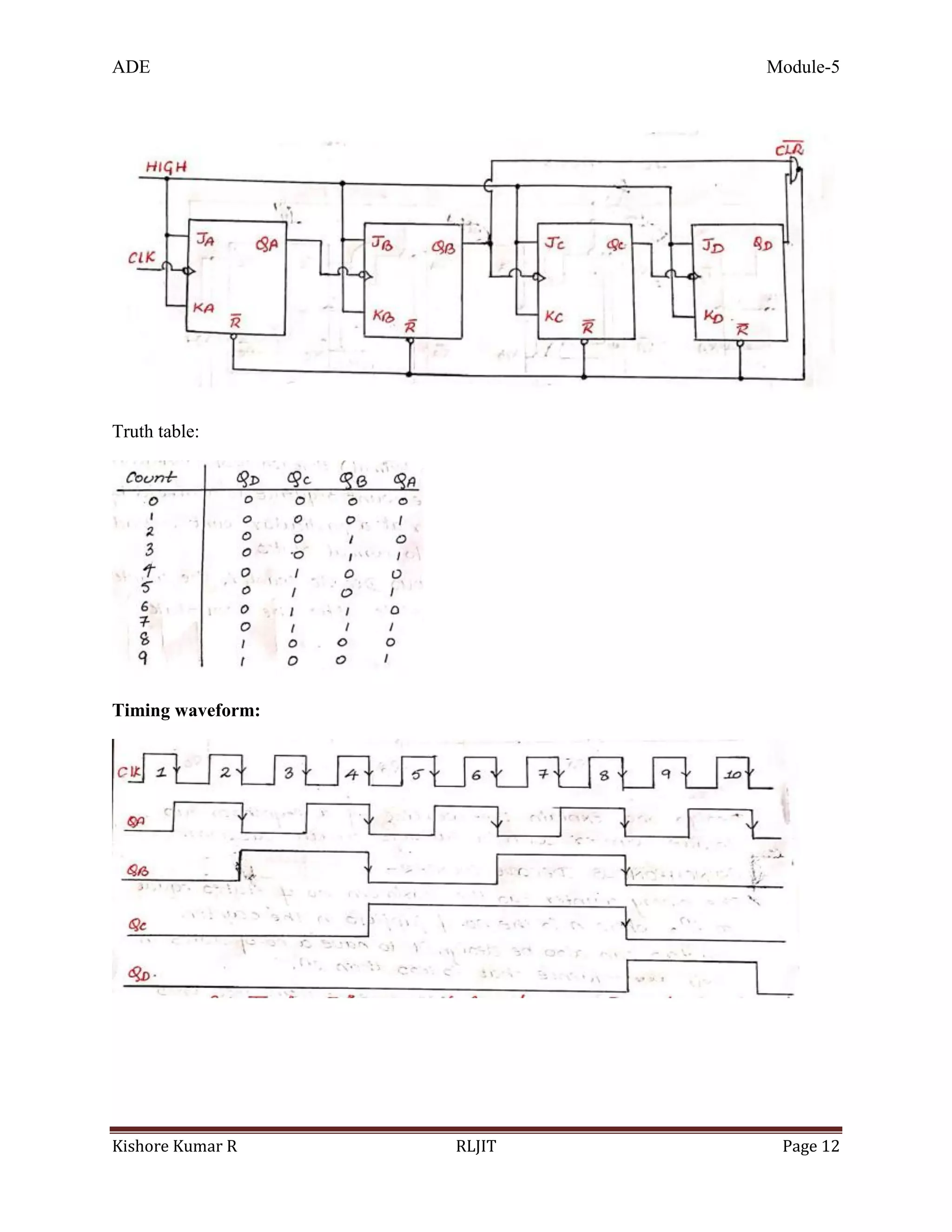
6. Design and explain working of Decade counter
7. Write Verilog code for MOD-8 Up counter
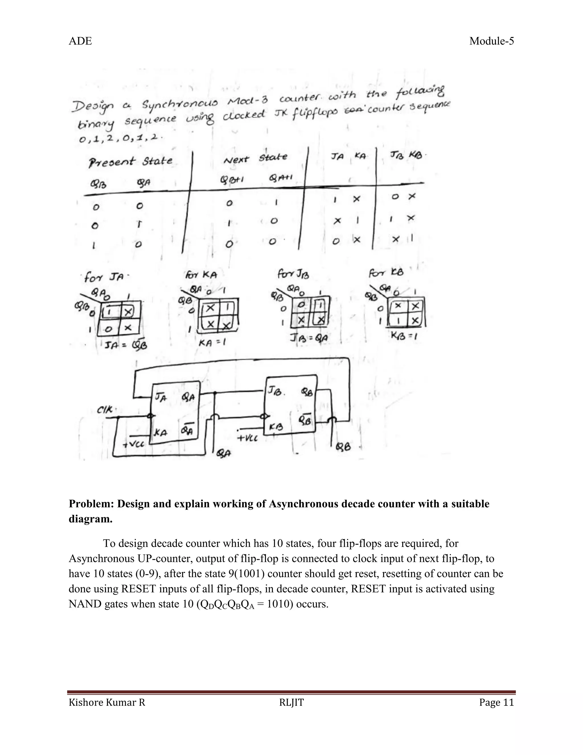
8. Design MOD-3 counter
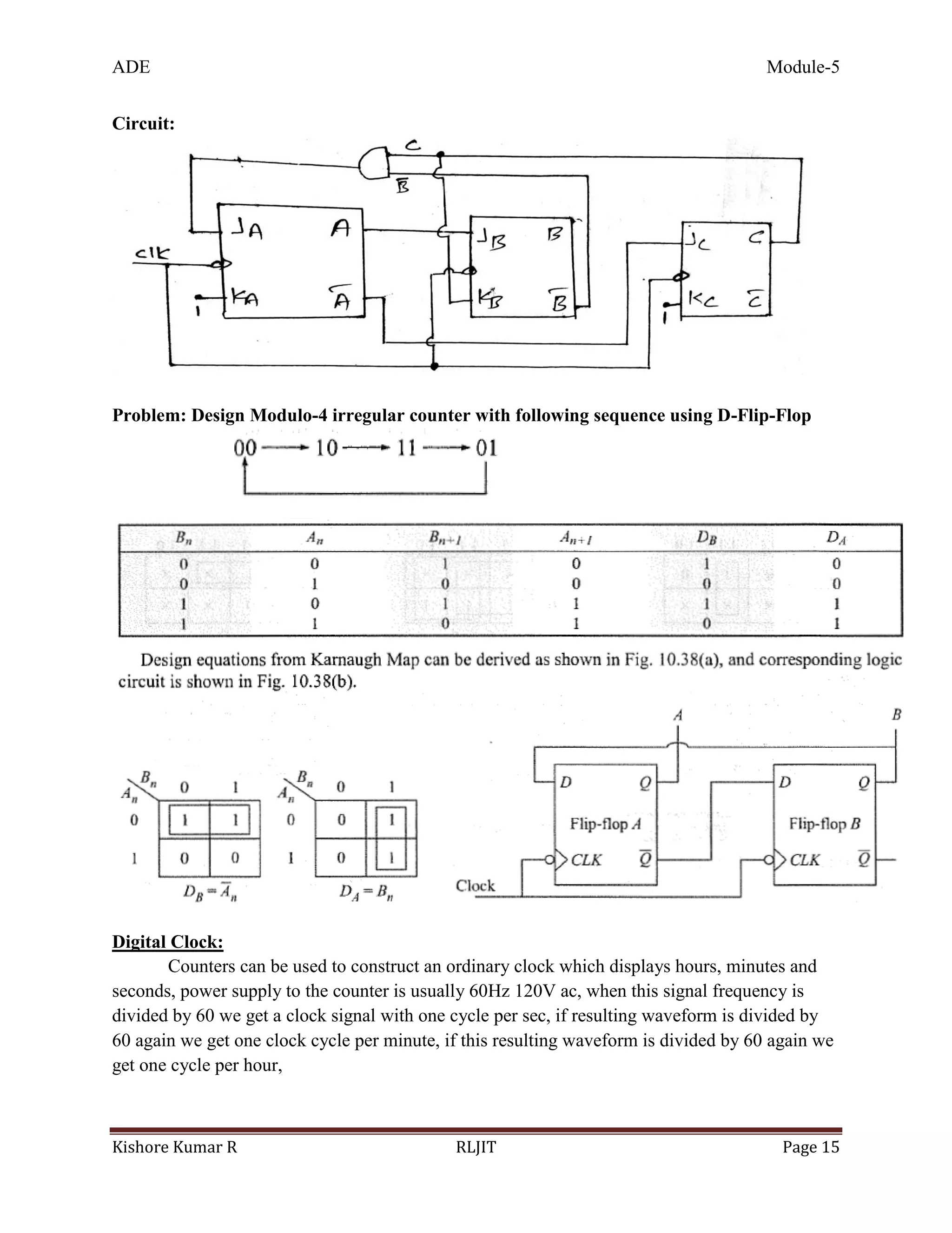
9. Design Modulo-4 irregular counter with following sequence using D-Flip-Flop](https://image.slidesharecdn.com/module-5-171226101633/75/15CS32-ADE-Module-5-17-2048.jpg)

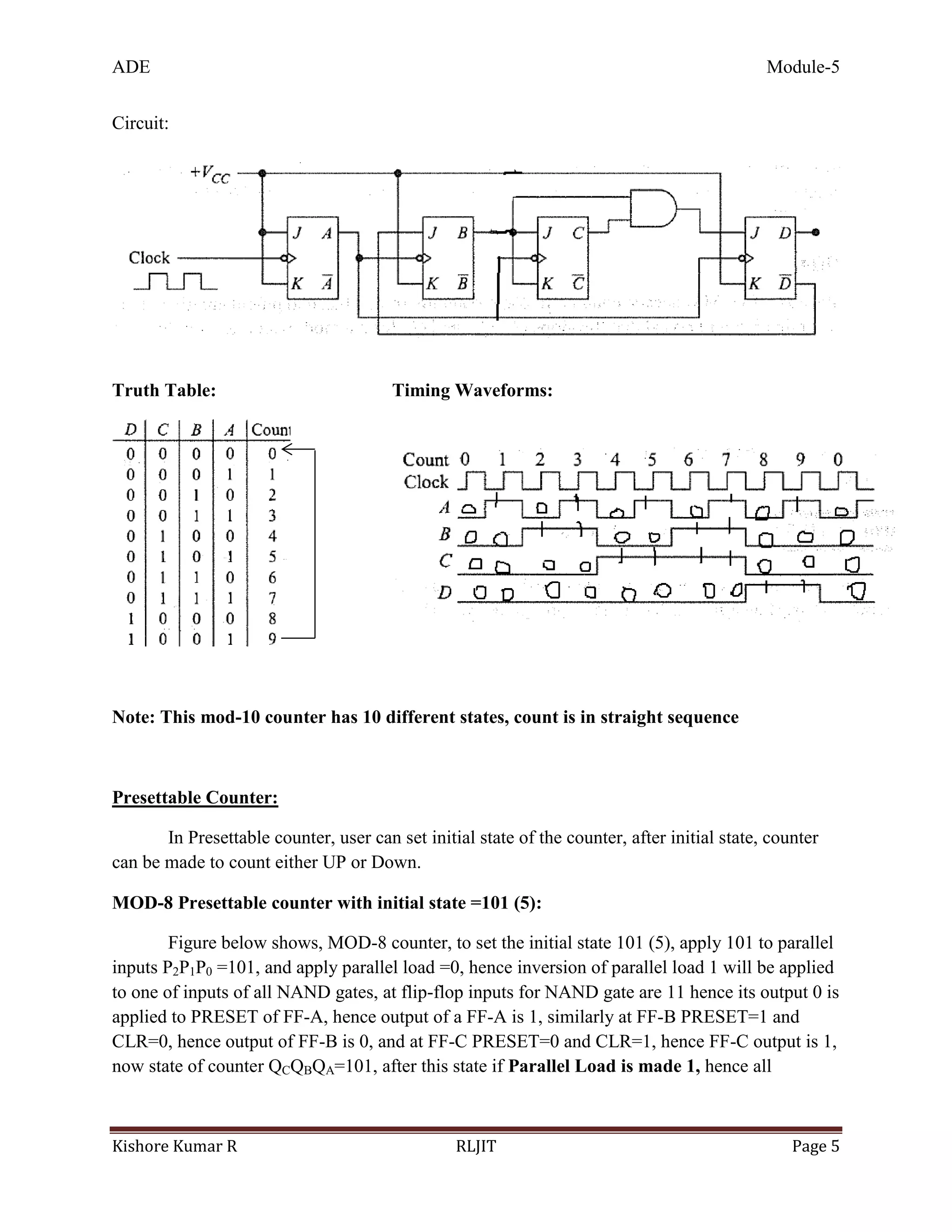
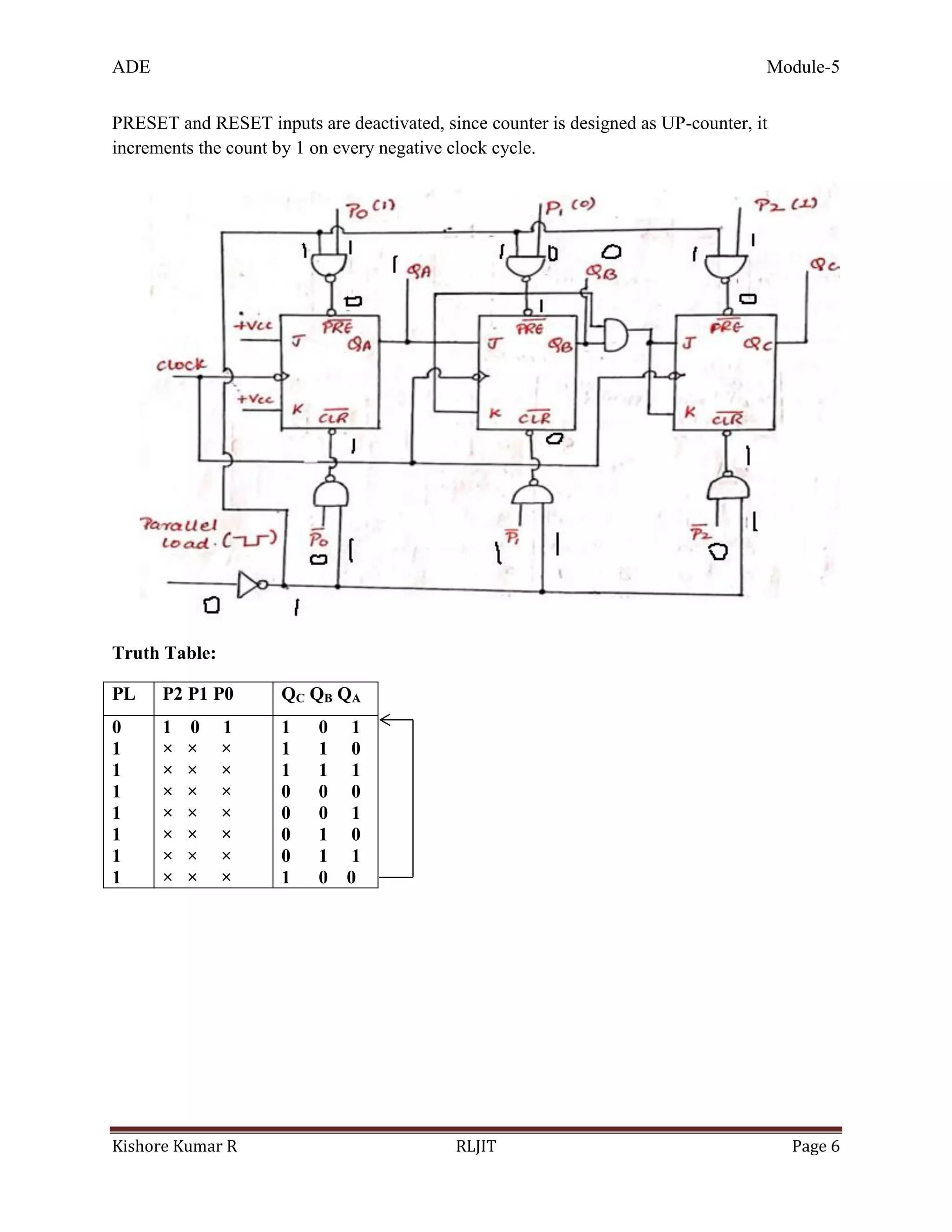
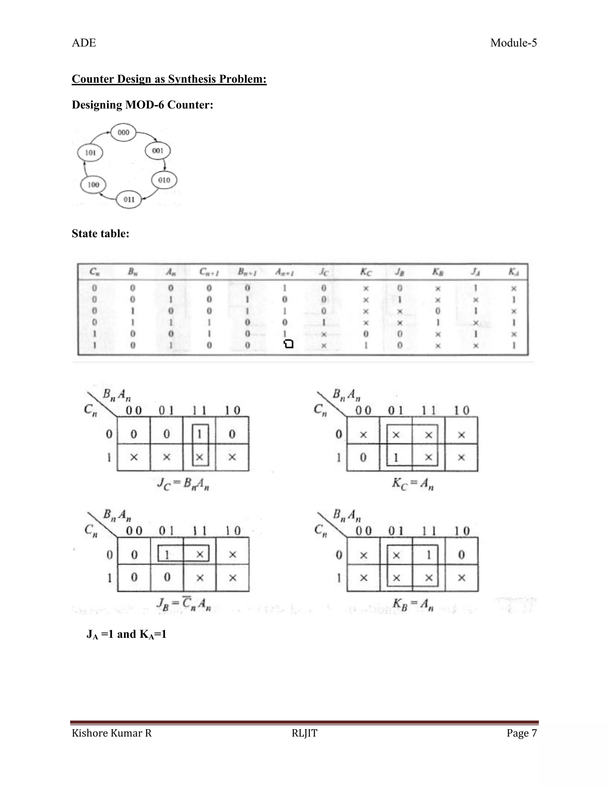
This document discusses various counter circuits including decade counters, presettable counters, and counter design using hardware description languages. It provides state tables and circuit diagrams for a decade counter, MOD-5 counter, presettable MOD-8 counter, and asynchronous decade counter. It also discusses using counters to build a digital clock and provides a block diagram. Verilog code is given for a MOD-8 up counter and down counter. The last pages cover important questions on designing various counters.