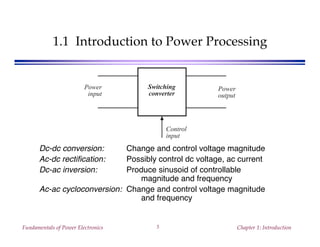
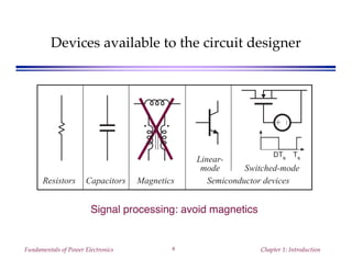
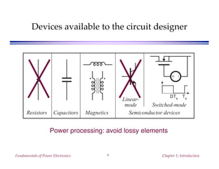
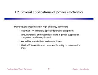
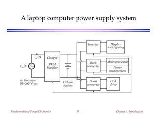
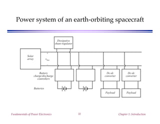
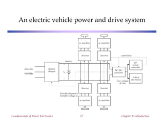
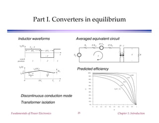
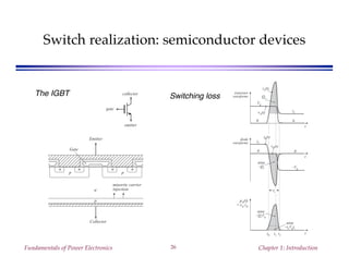
This document provides an introduction to power electronics. It discusses various power electronic applications including power supplies, motor drives, and utility transmission systems. It also covers common power electronic components like switches, capacitors, inductors, and semiconductor devices. The document outlines the topics that will be covered in the course, including converter circuit operation, control systems, magnetics design, rectifiers, and resonant converters.
A dual active bridge dc-dc converter for application in a smart user networkAlessandro Burgio
Abstract—The paper presents a dual active bridge converter, i.e. an isolated bidirectional DC/DC converter composed of two full-bridge DC/AC converters and an isolation high frequency (HF) transformer, useful for application in a DC-powered microgrid. The dual active bridge converter connects a battery energy storage system to a DC bus so to provide a high level of reliability and resilience to grid disturbances. In particular, the proposed converter ensures a stable DC bus voltage when the microgrid is operated in islanded mode. Numerical results demonstrate the good dynamic response of the converter under transient condition of
This ppt provides a brief overview on thyristors commonly known as SCRs. V- I characteristics curve, triggering methods, protection methods, series and parallel operations of SCRs, applications are discussed in this slide.
Seminor on resonant and soft switching converterAnup Kumar
Soft Switching Techniques Are Highly Recommended To Reduce Switching Losses And Conduction Losses, During Each Turning On & Turning Off of Power Electronics Devices.
Nowadays, it is very important to maintain voltage level. Controlling of that voltage is also important. This Presentation contains methods of voltage control.
Introduction to Power Electronics, Power Diodes, Thyristors and Power Transistors. Different types of Power Converters, Applications of Power Electronics and Peripheral effects.
The complete list of thyristor family members include diac (bidirectional diode thyristor), triac (bidirectional triode thyristor), SCR (silicon controlled rectifier), Shockley diode, SCS (silicon controlled switch), SBS (silicon bilateral switch), SUS (silicon unilateral switch) also known as complementary SCR or CSCR, LASCR (light activated SCR), LAS (light activated switch) and LASCS (light activated SCS).
Steady-state Analysis for Switched Electronic Systems Trough ComplementarityGianluca Angelone
A synthesis of my Ph.D. defense. It's about modeling and steady state analysis of switched electronic power converters, both in open and closed loop, by using the complementarity framework. Application examples: Buck, Boost, Resonant and Modular Multilevel Converters
In an electrical circuit the impedance of a component is defined as the ratio of the voltage phasor v, across the component over the current phasor I , through the component.
We looked at the data. Here’s a breakdown of some key statistics about the nation’s incoming presidents’ addresses, how long they spoke, how well, and more.
International Journal of Engineering Research and Development (IJERD)IJERD Editor
journal publishing, how to publish research paper, Call For research paper, international journal, publishing a paper, IJERD, journal of science and technology, how to get a research paper published, publishing a paper, publishing of journal, publishing of research paper, reserach and review articles, IJERD Journal, How to publish your research paper, publish research paper, open access engineering journal, Engineering journal, Mathemetics journal, Physics journal, Chemistry journal, Computer Engineering, Computer Science journal, how to submit your paper, peer reviw journal, indexed journal, reserach and review articles, engineering journal, www.ijerd.com, research journals,
yahoo journals, bing journals, International Journal of Engineering Research and Development, google journals, hard copy of journal
Extremely high duty cycle of boost converter may result in higher conduction losses. To achieve a high
conversion ratio without operating at extremely high duty ratio, some converters based on transformers or coupled
inductors or tapped inductors have been provided. However, the leakage inductance in the transformer, coupled
inductor or tapped inductor will cause high voltage spikes in the switches and reduce system efficiency. A novel
single switch cascaded dc-dc converter of boost and buck boost converters have extended voltage conversion ratio
to d/(1-d)2. The features of the converter are high voltage gain; only one switch for realizing the converter, the
number of magnetic components is small etc. So comparing with other topologies cascaded converter is more
effective. Simulation of the converter for a dc input voltage and fixed duty cycle was done, and the same was
verified experimentally for a low input voltage. The software used for simulation was MatlabR2014a
State of ICS and IoT Cyber Threat Landscape Report 2024 previewPrayukth K V
The IoT and OT threat landscape report has been prepared by the Threat Research Team at Sectrio using data from Sectrio, cyber threat intelligence farming facilities spread across over 85 cities around the world. In addition, Sectrio also runs AI-based advanced threat and payload engagement facilities that serve as sinks to attract and engage sophisticated threat actors, and newer malware including new variants and latent threats that are at an earlier stage of development.
The latest edition of the OT/ICS and IoT security Threat Landscape Report 2024 also covers:
State of global ICS asset and network exposure
Sectoral targets and attacks as well as the cost of ransom
Global APT activity, AI usage, actor and tactic profiles, and implications
Rise in volumes of AI-powered cyberattacks
Major cyber events in 2024
Malware and malicious payload trends
Cyberattack types and targets
Vulnerability exploit attempts on CVEs
Attacks on counties – USA
Expansion of bot farms – how, where, and why
In-depth analysis of the cyber threat landscape across North America, South America, Europe, APAC, and the Middle East
Why are attacks on smart factories rising?
Cyber risk predictions
Axis of attacks – Europe
Systemic attacks in the Middle East
Download the full report from here:
https://sectrio.com/resources/ot-threat-landscape-reports/sectrio-releases-ot-ics-and-iot-security-threat-landscape-report-2024/
GDG Cloud Southlake #33: Boule & Rebala: Effective AppSec in SDLC using Deplo...James Anderson
Effective Application Security in Software Delivery lifecycle using Deployment Firewall and DBOM
The modern software delivery process (or the CI/CD process) includes many tools, distributed teams, open-source code, and cloud platforms. Constant focus on speed to release software to market, along with the traditional slow and manual security checks has caused gaps in continuous security as an important piece in the software supply chain. Today organizations feel more susceptible to external and internal cyber threats due to the vast attack surface in their applications supply chain and the lack of end-to-end governance and risk management.
The software team must secure its software delivery process to avoid vulnerability and security breaches. This needs to be achieved with existing tool chains and without extensive rework of the delivery processes. This talk will present strategies and techniques for providing visibility into the true risk of the existing vulnerabilities, preventing the introduction of security issues in the software, resolving vulnerabilities in production environments quickly, and capturing the deployment bill of materials (DBOM).
Speakers:
Bob Boule
Robert Boule is a technology enthusiast with PASSION for technology and making things work along with a knack for helping others understand how things work. He comes with around 20 years of solution engineering experience in application security, software continuous delivery, and SaaS platforms. He is known for his dynamic presentations in CI/CD and application security integrated in software delivery lifecycle.
Gopinath Rebala
Gopinath Rebala is the CTO of OpsMx, where he has overall responsibility for the machine learning and data processing architectures for Secure Software Delivery. Gopi also has a strong connection with our customers, leading design and architecture for strategic implementations. Gopi is a frequent speaker and well-known leader in continuous delivery and integrating security into software delivery.
The Art of the Pitch: WordPress Relationships and SalesLaura Byrne
Clients don’t know what they don’t know. What web solutions are right for them? How does WordPress come into the picture? How do you make sure you understand scope and timeline? What do you do if sometime changes?
All these questions and more will be explored as we talk about matching clients’ needs with what your agency offers without pulling teeth or pulling your hair out. Practical tips, and strategies for successful relationship building that leads to closing the deal.
UiPath Test Automation using UiPath Test Suite series, part 4DianaGray10
Welcome to UiPath Test Automation using UiPath Test Suite series part 4. In this session, we will cover Test Manager overview along with SAP heatmap.
The UiPath Test Manager overview with SAP heatmap webinar offers a concise yet comprehensive exploration of the role of a Test Manager within SAP environments, coupled with the utilization of heatmaps for effective testing strategies.
Participants will gain insights into the responsibilities, challenges, and best practices associated with test management in SAP projects. Additionally, the webinar delves into the significance of heatmaps as a visual aid for identifying testing priorities, areas of risk, and resource allocation within SAP landscapes. Through this session, attendees can expect to enhance their understanding of test management principles while learning practical approaches to optimize testing processes in SAP environments using heatmap visualization techniques
What will you get from this session?
1. Insights into SAP testing best practices
2. Heatmap utilization for testing
3. Optimization of testing processes
4. Demo
Topics covered:
Execution from the test manager
Orchestrator execution result
Defect reporting
SAP heatmap example with demo
Speaker:
Deepak Rai, Automation Practice Lead, Boundaryless Group and UiPath MVP
Dev Dives: Train smarter, not harder – active learning and UiPath LLMs for do...UiPathCommunity
💥 Speed, accuracy, and scaling – discover the superpowers of GenAI in action with UiPath Document Understanding and Communications Mining™:
See how to accelerate model training and optimize model performance with active learning
Learn about the latest enhancements to out-of-the-box document processing – with little to no training required
Get an exclusive demo of the new family of UiPath LLMs – GenAI models specialized for processing different types of documents and messages
This is a hands-on session specifically designed for automation developers and AI enthusiasts seeking to enhance their knowledge in leveraging the latest intelligent document processing capabilities offered by UiPath.
Speakers:
👨🏫 Andras Palfi, Senior Product Manager, UiPath
👩🏫 Lenka Dulovicova, Product Program Manager, UiPath
UiPath Test Automation using UiPath Test Suite series, part 3DianaGray10
Welcome to UiPath Test Automation using UiPath Test Suite series part 3. In this session, we will cover desktop automation along with UI automation.
Topics covered:
UI automation Introduction,
UI automation Sample
Desktop automation flow
Pradeep Chinnala, Senior Consultant Automation Developer @WonderBotz and UiPath MVP
Deepak Rai, Automation Practice Lead, Boundaryless Group and UiPath MVP
Connector Corner: Automate dynamic content and events by pushing a buttonDianaGray10
Here is something new! In our next Connector Corner webinar, we will demonstrate how you can use a single workflow to:
Create a campaign using Mailchimp with merge tags/fields
Send an interactive Slack channel message (using buttons)
Have the message received by managers and peers along with a test email for review
But there’s more:
In a second workflow supporting the same use case, you’ll see:
Your campaign sent to target colleagues for approval
If the “Approve” button is clicked, a Jira/Zendesk ticket is created for the marketing design team
But—if the “Reject” button is pushed, colleagues will be alerted via Slack message
Join us to learn more about this new, human-in-the-loop capability, brought to you by Integration Service connectors.
And...
Speakers:
Akshay Agnihotri, Product Manager
Charlie Greenberg, Host
Neuro-symbolic is not enough, we need neuro-*semantic*Frank van Harmelen
Neuro-symbolic (NeSy) AI is on the rise. However, simply machine learning on just any symbolic structure is not sufficient to really harvest the gains of NeSy. These will only be gained when the symbolic structures have an actual semantics. I give an operational definition of semantics as “predictable inference”.
All of this illustrated with link prediction over knowledge graphs, but the argument is general.
Epistemic Interaction - tuning interfaces to provide information for AI supportAlan Dix
Paper presented at SYNERGY workshop at AVI 2024, Genoa, Italy. 3rd June 2024
https://alandix.com/academic/papers/synergy2024-epistemic/
As machine learning integrates deeper into human-computer interactions, the concept of epistemic interaction emerges, aiming to refine these interactions to enhance system adaptability. This approach encourages minor, intentional adjustments in user behaviour to enrich the data available for system learning. This paper introduces epistemic interaction within the context of human-system communication, illustrating how deliberate interaction design can improve system understanding and adaptation. Through concrete examples, we demonstrate the potential of epistemic interaction to significantly advance human-computer interaction by leveraging intuitive human communication strategies to inform system design and functionality, offering a novel pathway for enriching user-system engagements.
Essentials of Automations: Optimizing FME Workflows with ParametersSafe Software
Are you looking to streamline your workflows and boost your projects’ efficiency? Do you find yourself searching for ways to add flexibility and control over your FME workflows? If so, you’re in the right place.
Join us for an insightful dive into the world of FME parameters, a critical element in optimizing workflow efficiency. This webinar marks the beginning of our three-part “Essentials of Automation” series. This first webinar is designed to equip you with the knowledge and skills to utilize parameters effectively: enhancing the flexibility, maintainability, and user control of your FME projects.
Here’s what you’ll gain:
- Essentials of FME Parameters: Understand the pivotal role of parameters, including Reader/Writer, Transformer, User, and FME Flow categories. Discover how they are the key to unlocking automation and optimization within your workflows.
- Practical Applications in FME Form: Delve into key user parameter types including choice, connections, and file URLs. Allow users to control how a workflow runs, making your workflows more reusable. Learn to import values and deliver the best user experience for your workflows while enhancing accuracy.
- Optimization Strategies in FME Flow: Explore the creation and strategic deployment of parameters in FME Flow, including the use of deployment and geometry parameters, to maximize workflow efficiency.
- Pro Tips for Success: Gain insights on parameterizing connections and leveraging new features like Conditional Visibility for clarity and simplicity.
We’ll wrap up with a glimpse into future webinars, followed by a Q&A session to address your specific questions surrounding this topic.
Don’t miss this opportunity to elevate your FME expertise and drive your projects to new heights of efficiency.
Securing your Kubernetes cluster_ a step-by-step guide to success !KatiaHIMEUR1
Today, after several years of existence, an extremely active community and an ultra-dynamic ecosystem, Kubernetes has established itself as the de facto standard in container orchestration. Thanks to a wide range of managed services, it has never been so easy to set up a ready-to-use Kubernetes cluster.
However, this ease of use means that the subject of security in Kubernetes is often left for later, or even neglected. This exposes companies to significant risks.
In this talk, I'll show you step-by-step how to secure your Kubernetes cluster for greater peace of mind and reliability.
Key Trends Shaping the Future of Infrastructure.pdfCheryl Hung
Keynote at DIGIT West Expo, Glasgow on 29 May 2024.
Cheryl Hung, ochery.com
Sr Director, Infrastructure Ecosystem, Arm.
The key trends across hardware, cloud and open-source; exploring how these areas are likely to mature and develop over the short and long-term, and then considering how organisations can position themselves to adapt and thrive.
Key Trends Shaping the Future of Infrastructure.pdf
Chapter 01
1. Fundamentals of Power Electronics Chapter 1: Introduction1
Fundamentals of Power Electronics
Second edition
Robert W. Erickson
Dragan Maksimovic
University of Colorado, Boulder
2. Fundamentals of Power Electronics Chapter 1: Introduction2
Chapter 1: Introduction
1.1. Introduction to power processing
1.2. Some applications of power electronics
1.3. Elements of power electronics
Summary of the course
3. Fundamentals of Power Electronics Chapter 1: Introduction3
1.1 Introduction to Power Processing
Dc-dc conversion: Change and control voltage magnitude
Ac-dc rectification: Possibly control dc voltage, ac current
Dc-ac inversion: Produce sinusoid of controllable
magnitude and frequency
Ac-ac cycloconversion: Change and control voltage magnitude
and frequency
Switching
converter
Power
input
Power
output
Control
input
4. Fundamentals of Power Electronics Chapter 1: Introduction4
Control is invariably required
Switching
converter
Power
input
Power
output
Control
input
Controller
reference
feedbackfeedforward
5. Fundamentals of Power Electronics Chapter 1: Introduction5
High efficiency is essential
High efficiency leads to low
power loss within converter
Small size and reliable operation
is then feasible
Efficiency is a good measure of
converter performance
0 0.5 1 1.5
0.2
0.4
0.6
0.8
1
Ploss / Pout
ηη =
Pout
Pin
Ploss = Pin – Pout = Pout
1
η – 1
6. Fundamentals of Power Electronics Chapter 1: Introduction6
A high-efficiency converter
A goal of current converter technology is to construct converters of small
size and weight, which process substantial power at high efficiency
Converter
Pin Pout
7. Fundamentals of Power Electronics Chapter 1: Introduction7
Devices available to the circuit designer
DTs Ts
Resistors Capacitors Magnetics Semiconductor devices
Linear-
mode
+
–
Switched-mode
8. Fundamentals of Power Electronics Chapter 1: Introduction8
Devices available to the circuit designer
Signal processing: avoid magnetics
DTs Ts
Resistors Capacitors Magnetics Semiconductor devices
Linear-
mode
+
–
Switched-mode
9. Fundamentals of Power Electronics Chapter 1: Introduction9
Devices available to the circuit designer
Power processing: avoid lossy elements
DTs Ts
Resistors Capacitors Magnetics Semiconductor devices
Linear-
mode
+
–
Switched-mode
10. Fundamentals of Power Electronics Chapter 1: Introduction10
Power loss in an ideal switch
Switch closed: v(t) = 0
Switch open: i(t) = 0
In either event: p(t) = v(t) i(t) = 0
Ideal switch consumes zero power
+
v(t)
–
i(t)
11. Fundamentals of Power Electronics Chapter 1: Introduction11
A simple dc-dc converter example
Input source: 100V
Output load: 50V, 10A, 500W
How can this converter be realized?
+
–
R
5Ω
+
V
50V
–
Vg
100V
I
10A
Dc-dc
converter
12. Fundamentals of Power Electronics Chapter 1: Introduction12
Dissipative realization
Resistive voltage divider
+
–
R
5Ω
+
V
50V
–
Vg
100V
I
10A
+ 50V –
Ploss = 500W
Pout = 500WPin = 1000W
13. Fundamentals of Power Electronics Chapter 1: Introduction13
Dissipative realization
Series pass regulator: transistor operates in
active region
+
–
R
5Ω
+
V
50V
–
Vg
100V
I
10A+ 50V –
Ploss ≈ 500W
Pout = 500WPin ≈ 1000W
+–linear amplifier
and base driver
Vref
14. Fundamentals of Power Electronics Chapter 1: Introduction14
Use of a SPDT switch
+
–
R
+
v(t)
50 V
–
1
2
+
vs(t)
–
Vg
100 V
I
10 A
vs(t)
Vg
DTs
(1 – D) Ts
0
t
switch
position: 1 2 1
Vs = DVg
15. Fundamentals of Power Electronics Chapter 1: Introduction15
The switch changes the dc voltage level
D = switch duty cycle
0 ≤ D ≤ 1
Ts = switching period
fs = switching frequency
= 1 / Ts
Vs = 1
Ts
vs(t) dt
0
Ts
= DVg
DC component of vs(t) = average value:
vs(t)
Vg
DTs
(1 – D) Ts
0
t
switch
position: 1 2 1
Vs = DVg
16. Fundamentals of Power Electronics Chapter 1: Introduction16
Addition of low pass filter
Addition of (ideally lossless) L-C low-pass filter, for
removal of switching harmonics:
• Choose filter cutoff frequency f0 much smaller than switching
frequency fs
• This circuit is known as the “buck converter”
+
–
R
+
v(t)
–
1
2
+
vs(t)
–
Vg
100 V
i(t)
L
C
Ploss small
Pout = 500 WPin ≈ 500 W
17. Fundamentals of Power Electronics Chapter 1: Introduction17
Addition of control system
for regulation of output voltage
δ(t)
TsdTs t
+
–
+
v
–
vg
Switching converterPower
input
Load
–+
Compensator
vref
Reference
input
HvPulse-width
modulator
vc
Transistor
gate driver
δ Gc(s)
H(s)
ve
Error
signal
Sensor
gain
i
18. Fundamentals of Power Electronics Chapter 1: Introduction18
The boost converter
+
–
L
C R
+
V
–
1
2
Vg
D
0 0.2 0.4 0.6 0.8 1
V
5Vg
4Vg
3Vg
2Vg
Vg
0
19. Fundamentals of Power Electronics Chapter 1: Introduction19
A single-phase inverter
1
2
+
–
load
+ v(t) –
2
1
Vg
vs(t)
+ –
t
vs(t) “H-bridge”
Modulate switch
duty cycles to
obtain sinusoidal
low-frequency
component
20. Fundamentals of Power Electronics Chapter 1: Introduction20
1.2 Several applications of power electronics
Power levels encountered in high-efficiency converters
• less than 1 W in battery-operated portable equipment
• tens, hundreds, or thousands of watts in power supplies for
computers or office equipment
• kW to MW in variable-speed motor drives
• 1000 MW in rectifiers and inverters for utility dc transmission
lines
21. Fundamentals of Power Electronics Chapter 1: Introduction21
A laptop computer power supply system
vac(t)
iac(t) Charger
PWM
Rectifier
Lithium
battery
ac line input
85–265 Vrms
Inverter
Buck
converter
Boost
converter
Display
backlighting
Microprocessor
Power
management
Disk
drive
22. Fundamentals of Power Electronics Chapter 1: Introduction22
Power system of an earth-orbiting spacecraft
Solar
array
+
vbus
–
Batteries
Battery
charge/discharge
controllers
Dc-dc
converter
Payload
Dc-dc
converter
Payload
Dissipative
shunt regulator
23. Fundamentals of Power Electronics Chapter 1: Introduction23
An electric vehicle power and drive system
3øac line
50/60 Hz
Battery
charger
battery
+
vb
–
Variable-frequency
Variable-voltage ac
Inverter
ac machine
Inverter
Inverter
ac machine
DC-DC
converter
µP
system
controller
Vehicle
electronicsLow-voltage
dc bus
control bus
ac machine ac machine
Inverter
24. Fundamentals of Power Electronics Chapter 1: Introduction24
1.3 Elements of power electronics
Power electronics incorporates concepts from the fields of
analog circuits
electronic devices
control systems
power systems
magnetics
electric machines
numerical simulation
25. Fundamentals of Power Electronics Chapter 1: Introduction25
Part I. Converters in equilibrium
iL(t)
t0 DTs
Ts
I
iL(0) Vg – V
L
iL(DTs)
∆iL
– V
L
vL(t) Vg – V
t
– V
D'TsDTs
switch
position: 1 2 1
RL
+
–Vg
D' RD
+
–
D' VDD Ron
R
+
V
–
I
D' : 1
Inductor waveforms Averaged equivalent circuit
D
η RL/R = 0.1
0.02
0.01
0.05
0.002
0 0.1 0.2 0.3 0.4 0.5 0.6 0.7 0.8 0.9 1
0%
10%
20%
30%
40%
50%
60%
70%
80%
90%
100%
Predicted efficiency
Discontinuous conduction mode
Transformer isolation
26. Fundamentals of Power Electronics Chapter 1: Introduction26
Switch realization: semiconductor devices
Collector
p
n-
n n
p p
Emitter
Gate
nn
minority carrier
injection
collector
emitter
gate
The IGBT
t
iL
–Vg
0
iB(t)
vB(t)
area
–Qr
0
tr
t
iL
Vg
0
iA(t)
vA(t)
Qr
0
t
area
~QrVg
area
~iLVgtr
t0 t1 t2
transistor
waveforms
diode
waveforms
pA(t)
= vA iA
Switching loss
27. Fundamentals of Power Electronics Chapter 1: Introduction27
Part I. Converters in equilibrium
2. Principles of steady state converter analysis
3. Steady-state equivalent circuit modeling, losses, and efficiency
4. Switch realization
5. The discontinuous conduction mode
6. Converter circuits
28. Fundamentals of Power Electronics Chapter 1: Introduction28
Part II. Converter dynamics and control
+
–
+
v(t)
–
vg(t)
Switching converterPower
input
Load
–+
R
compensator
Gc(s)
vref
voltage
reference
v
feedback
connection
pulse-width
modulator
vc
transistor
gate driver
δ(t)
δ(t)
TsdTs t t
vc(t)
Controller
t
t
gate
drive
actual waveform v(t)
including ripple
averaged waveform <v(t)>Ts
with ripple neglected
+
– I d(t)vg(t)
+
–
L
Vg – V d(t)
+
v(t)
–
RCI d(t)
1 : D D' : 1
Closed-loop converter system Averaging the waveforms
Small-signal
averaged
equivalent circuit
29. Fundamentals of Power Electronics Chapter 1: Introduction29
Part II. Converter dynamics and control
7. Ac modeling
8. Converter transfer functions
9. Controller design
10. Input filter design
11. Ac and dc equivalent circuit modeling of the discontinuous
conduction mode
12. Current-programmed control
30. Fundamentals of Power Electronics Chapter 1: Introduction30
Part III. Magnetics
Φ
i
–i
3i
–2i
2i
2Φ
current
density
J
dlayer
1
layer
2
layer
3
0
0.02
0.04
0.06
0.08
0.1
Switching frequency
Bmax(T)
25kHz 50kHz 100kHz 200kHz 250kHz 400kHz 500kHz 1000kHz
Potcoresize
4226
3622
2616
2213
1811 1811
2213
2616
n1 : n2
: nk
R1 R2
Rk
i1(t) i2(t)
ik(t)
LM
iM(t)transformer
design
transformer
size vs.
switching
frequency
the
proximity
effect
31. Fundamentals of Power Electronics Chapter 1: Introduction31
Part III. Magnetics
13. Basic magnetics theory
14. Inductor design
15. Transformer design
32. Fundamentals of Power Electronics Chapter 1: Introduction32
Part IV. Modern rectifiers,
and power system harmonics
100%
91%
73%
52%
32%
19% 15% 15% 13% 9%
0%
20%
40%
60%
80%
100%
1 3 5 7 9 11 13 15 17 19
Harmonic number
Harmonicamplitude,
percentoffundamental
THD = 136%
Distortion factor = 59%
Pollution of power system by
rectifier current harmonics
Re(vcontrol)
+
–
vac(t)
iac(t)
vcontrol
v(t)
i(t)
+
–
p(t) = vac
2
/ Re
Ideal rectifier (LFR)
ac
input
dc
output
boost converter
controller
Rvac(t)
iac(t) +
vg(t)
–
ig(t)
ig(t)vg(t)
+
v(t)
–
i(t)
Q1
L
C
D1
vcontrol(t)
multiplier X
+–
vref(t)
= kx vg(t) vcontrol(t)
Rs
va(t)
Gc(s)
PWM
compensator
verr(t)
A low-harmonic rectifier system
Model of
the ideal
rectifier
33. Fundamentals of Power Electronics Chapter 1: Introduction33
Part IV. Modern rectifiers,
and power system harmonics
16. Power and harmonics in nonsinusoidal systems
17. Line-commutated rectifiers
18. Pulse-width modulated rectifiers
34. Fundamentals of Power Electronics Chapter 1: Introduction34
Part V. Resonant converters
L
+
–
Vg
CQ1
Q2
Q3
Q4
D1
D2
D3
D4
1 : n
R
+
V
–
0
0.1
0.2
0.3
0.4
0.5
0.6
0.7
0.8
0.9
1
0 0.2 0.4 0.6 0.8 1 1.2 1.4 1.6 1.8 2
M=V/Vg
F = fs / f0
Q = 20
10
5
3.5
2
1.5
1
0.75
0.5
0.35
Q = 0.2
Q = 20
10
5
3.5
2
1.5
1
0.75
0.5
0.35
Q = 0.2
The series resonant converter
Dc
characteristics
conducting
devices:
t
Vg
vds1(t)
Q1
Q4
D2
D3
turn off
Q1
, Q4
commutation
interval
X
Zero voltage
switching
35. Fundamentals of Power Electronics Chapter 1: Introduction35
Part V. Resonant converters
19. Resonant conversion
20. Soft switching
36. Fundamentals of Power Electronics Chapter 1: Introduction36
Appendices
A. RMS values of commonly-observed converter waveforms
B. Simulation of converters
C. Middlebrook’s extra element theorem
D. Magnetics design tables
2
1
3
4
5
CCM-DCM1
+
–
+
–
+
–
C2
50 µH
11 kΩ
500 µF
Vg
28 V
L
C
R
vref
5 V
+12 V
LM324
R1
R2
R3 C3
R4
85 kΩ
1.1 nF2.7 nF
47 kΩ
120 kΩ
vz
–vyvx
Epwm
VM = 4 V
value = {LIMIT(0.25 vx, 0.1, 0.9)}
+
v
–
iLOAD1 2 3
4
5678
.nodeset v(3)=15 v(5)=5 v(6)=4.144 v(8)=0.536
Xswitch
L = 50 µΗ
fs = 100 kΗz
f
|| Gvg ||
–60 dB
–80 dB
0 dB
20 dB
5 Hz 50 Hz 5 kHz 50 kHz500 Hz
R = 3 Ω
R = 25 Ω
–40 dB
–20 dB
Open loop, d(t) = constant
Closed loop