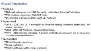
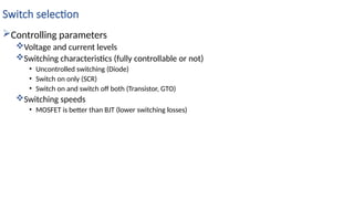
Introduction to Power Electronics
Source: Daniel Hart
Electrical Engineering
Muhammad Jafar
Personal Introduction
Academic
PhD electrical engineering, 2013, Norwegian University of Science & Technology
MSc electrical engineering, 2008, UET Taxila
BSc electrical engineering, 1998, NWFP UET Peshawar
Professional
2012 – 2018, DNV GL, A Norwegian multinational testing, inspection, certification, and
advisory company
2004 – 2008, CIIT Wah Cantt., Educational institution
1999 – 2004, Siemens Islamabad, A German multinational working in the electric power
products and projects business
Specialization
Electrical power engineering
Power electronics
HVDC, FACTS, renewable energy, microgrids
Course Information
Grading
Quiz (20%), sessinals (30%), and final (50%)
Absolute grading (means below 50% will fail)
Class rules
Mobiles switched off
Please be on time
Behavior
Please cooperate
Tolerate my tantrums! (I will try to be nice)
Provide feedback
Power engineering careers
Time/space Designer Supplier User
Pre-feasibility   
Feasibility   
Engineering   
Construction   
Operation   
De-commissioning   
Overview of applications of power electronics
Wikipedia article
Electrical4u article
Introduction to power Electronics
Power Electronics
Converter Classification
Power Electronics Concepts
Electronic Switches
Switch Selection
The Voltage-Controlled Switch
Transistors
Diodes
Thyristors (SCRs)
What we will discuss
What is Power Electronics?
The need for Power Conversion
Power Electronic Systems
Classification of Power Converter Circuits
Power Semiconductor Devices
Converter Modeling and Control
Applications of Power Electronics
Future Trends
Power Electronics
Power electronics?
Circuits that convert electric power from one form to another (AC/DC, DC/AC, DC/DC,
AC/AC).
Power electronics circuit function?
using semiconductor devices as switches
thereby controlling or modifying a voltage or current.
Electronics deals with
The semiconductor devices and circuits used in signal
processing to implement the control functions
Power deals with
Both static and rotating equipment that use electric
power
Control deals with
The steady-state stability of the closed-loop system
during the power conversion process
Convertor classification
The objective of a power electronics circuit
match the voltage and current requirements of the
load to those of the source.
Power electronics circuits convert one type or
level of a voltage or current to another
hence called converters.
Typical applications of power electronics
include
Rectification - Conversion of AC to DC
Inversion - Conversion of DC to AC
Conversion - Conversion of an unregulated DC
voltage to a regulated DC voltage
Cycloconversion - Conversion of an AC power
source from one amplitude and frequency to
another amplitude and frequency
Bidirectional converter
Power can go both ways
Multistep conversion
When just one converter cannot do the job
Power Electronics Concepts
Need 3-V DC voltage level across from a 9-V
battery
Simple solution using voltage divider ( and )
Issues
Power absorbed and lost by the resistor
Efficiency 33%
If changes and fixed, changes
Power Electronics Concepts
Possible solution
Using a transistor instead of to maintain 6V across
it and 3V across
Efficiency is low
Power Electronics Concepts
Solution: Fig (a)
Periodic opening and closing of the switch Fig (b)
Output: not a constant dc voltage
the average value is 1/3 of the source voltage
Power absorbed by switch
When closed ,
When opened ,
Efficiency=100%
Power Electronics Concepts
 Contains a DC term but is pulsating
To create a 3-V DC voltage, is applied to a low-pass (LP) filter
An ideal LP filter blocks pulsations and allows DC to pass
through
If the filter is lossless, the converter will be 100 percent
efficient
Power Electronics Concepts
System control
Outputs such as voltage and current are
measured, and operating parameters are
adjusted to maintain the desired output.
For example, if the 9-V battery output
decreases to 6 V, the switch would have to be
closed 50 percent of the time to maintain an
average value of 3 V for .
A feedback control system would detect if the
average output voltage is not 3 V and adjust
the closing and opening of the switch
accordingly
Electronic Switches
Two state device: On or off (ideally short-circuit or open circuit)
Short-circuit or on:
Switch voltage is zero
Zero power loss
Open-circuit or off
Switch current is zero
Zero power loss
Real switches are not ideal, but power loss is small
The Diode
Uncontrolled switch
Voltage and current dictate when it turns
on and when it turns off
Current reverses momentarily when
the diode switches off
Time associated is called reverse
recovery time (<1us)
Schottky diode: metal silicon barrier
instead of p-n junction
Faster
Smaller voltage drop
Reverse recovery transients absent
Thyristor
Controllable diode
Turn-on control
Turn-off not controlled externally
GTO is fully controllable
Also called silicon controlled
rectifier (SCR)
Can handle large voltage and
current
Relatively low frequency application
GTO needs significant current (1/3
of anode current) to switch off
Triac conducts current in either
direction (dimmer application)
MCT is similar to GTO but needs
smaller turn-off gate current
Transistors
Fully controllable
Several types
MOSFET
BJT
IGBT
MOSFET
Higher switching frequencies
than BJT
Turns on with gate voltage
Transistors
BJT
Turns on with base current
Needs sufficient base current
Power hungry
Darlington is a solution to high
base current requirement
Transistors
IGBT
Combination of MOSFET and BJT
Low power to switch on
Low on-state resistance
Have replaced BJTs in most applications
Switch selection
Controlling parameters
Voltage and current levels
Switching characteristics (fully controllable or not)
• Uncontrolled switching (Diode)
• Switch on only (SCR)
• Switch on and switch off both (Transistor, GTO)
Switching speeds
• MOSFET is better than BJT (lower switching losses)

LecturesPEChapter01IntroductionToPowerElectronics.pptx

  • 1.
    Introduction to PowerElectronics Source: Daniel Hart Electrical Engineering Muhammad Jafar
  • 2.
    Personal Introduction Academic PhD electricalengineering, 2013, Norwegian University of Science & Technology MSc electrical engineering, 2008, UET Taxila BSc electrical engineering, 1998, NWFP UET Peshawar Professional 2012 – 2018, DNV GL, A Norwegian multinational testing, inspection, certification, and advisory company 2004 – 2008, CIIT Wah Cantt., Educational institution 1999 – 2004, Siemens Islamabad, A German multinational working in the electric power products and projects business Specialization Electrical power engineering Power electronics HVDC, FACTS, renewable energy, microgrids
  • 3.
    Course Information Grading Quiz (20%),sessinals (30%), and final (50%) Absolute grading (means below 50% will fail) Class rules Mobiles switched off Please be on time Behavior Please cooperate Tolerate my tantrums! (I will try to be nice) Provide feedback
  • 4.
    Power engineering careers Time/spaceDesigner Supplier User Pre-feasibility    Feasibility    Engineering    Construction    Operation    De-commissioning   
  • 5.
    Overview of applicationsof power electronics Wikipedia article Electrical4u article
  • 6.
    Introduction to powerElectronics Power Electronics Converter Classification Power Electronics Concepts Electronic Switches Switch Selection The Voltage-Controlled Switch Transistors Diodes Thyristors (SCRs)
  • 7.
    What we willdiscuss What is Power Electronics? The need for Power Conversion Power Electronic Systems Classification of Power Converter Circuits Power Semiconductor Devices Converter Modeling and Control Applications of Power Electronics Future Trends
  • 8.
    Power Electronics Power electronics? Circuitsthat convert electric power from one form to another (AC/DC, DC/AC, DC/DC, AC/AC). Power electronics circuit function? using semiconductor devices as switches thereby controlling or modifying a voltage or current.
  • 9.
    Electronics deals with Thesemiconductor devices and circuits used in signal processing to implement the control functions Power deals with Both static and rotating equipment that use electric power Control deals with The steady-state stability of the closed-loop system during the power conversion process
  • 10.
    Convertor classification The objectiveof a power electronics circuit match the voltage and current requirements of the load to those of the source. Power electronics circuits convert one type or level of a voltage or current to another hence called converters. Typical applications of power electronics include Rectification - Conversion of AC to DC Inversion - Conversion of DC to AC Conversion - Conversion of an unregulated DC voltage to a regulated DC voltage Cycloconversion - Conversion of an AC power source from one amplitude and frequency to another amplitude and frequency
  • 11.
    Bidirectional converter Power cango both ways Multistep conversion When just one converter cannot do the job
  • 12.
    Power Electronics Concepts Need3-V DC voltage level across from a 9-V battery Simple solution using voltage divider ( and ) Issues Power absorbed and lost by the resistor Efficiency 33% If changes and fixed, changes
  • 13.
    Power Electronics Concepts Possiblesolution Using a transistor instead of to maintain 6V across it and 3V across Efficiency is low
  • 14.
    Power Electronics Concepts Solution:Fig (a) Periodic opening and closing of the switch Fig (b) Output: not a constant dc voltage the average value is 1/3 of the source voltage Power absorbed by switch When closed , When opened , Efficiency=100%
  • 15.
    Power Electronics Concepts Contains a DC term but is pulsating To create a 3-V DC voltage, is applied to a low-pass (LP) filter An ideal LP filter blocks pulsations and allows DC to pass through If the filter is lossless, the converter will be 100 percent efficient
  • 16.
    Power Electronics Concepts Systemcontrol Outputs such as voltage and current are measured, and operating parameters are adjusted to maintain the desired output. For example, if the 9-V battery output decreases to 6 V, the switch would have to be closed 50 percent of the time to maintain an average value of 3 V for . A feedback control system would detect if the average output voltage is not 3 V and adjust the closing and opening of the switch accordingly
  • 17.
    Electronic Switches Two statedevice: On or off (ideally short-circuit or open circuit) Short-circuit or on: Switch voltage is zero Zero power loss Open-circuit or off Switch current is zero Zero power loss Real switches are not ideal, but power loss is small
  • 18.
    The Diode Uncontrolled switch Voltageand current dictate when it turns on and when it turns off Current reverses momentarily when the diode switches off Time associated is called reverse recovery time (<1us) Schottky diode: metal silicon barrier instead of p-n junction Faster Smaller voltage drop Reverse recovery transients absent
  • 19.
    Thyristor Controllable diode Turn-on control Turn-offnot controlled externally GTO is fully controllable Also called silicon controlled rectifier (SCR) Can handle large voltage and current Relatively low frequency application GTO needs significant current (1/3 of anode current) to switch off Triac conducts current in either direction (dimmer application) MCT is similar to GTO but needs smaller turn-off gate current
  • 20.
  • 21.
    Transistors BJT Turns on withbase current Needs sufficient base current Power hungry Darlington is a solution to high base current requirement
  • 22.
    Transistors IGBT Combination of MOSFETand BJT Low power to switch on Low on-state resistance Have replaced BJTs in most applications
  • 23.
    Switch selection Controlling parameters Voltageand current levels Switching characteristics (fully controllable or not) • Uncontrolled switching (Diode) • Switch on only (SCR) • Switch on and switch off both (Transistor, GTO) Switching speeds • MOSFET is better than BJT (lower switching losses)