Downloaded 155 times

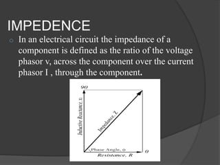
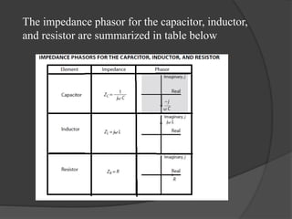


The document discusses the concept of impedance in electrical circuits, defined as the ratio of voltage phasor to current phasor. It explains how positive and negative phase angles correspond to specific positions of the phasor and describes the behavior of capacitors and inductors regarding voltage and current timing. Additionally, it highlights the mathematical differentiation of sinusoidal functions and the representation of component impedance.


