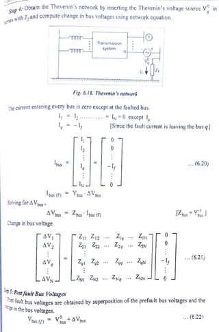
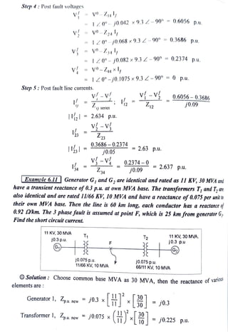
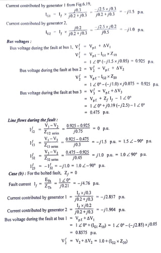
(1) A symmetrical fault occurs on bus 3 of a 3-bus system.
(2) The Thevenin equivalent impedance is calculated to be j0.21 p.u.
(3) For a fault impedance of j0.19 p.u., the fault current is calculated to be -j2.5 p.u. and the post-fault bus voltages are determined.
(4) For a bolted fault with zero impedance, the fault current is -j4.76 p.u. and the post-fault bus voltages and line currents are found.
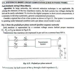
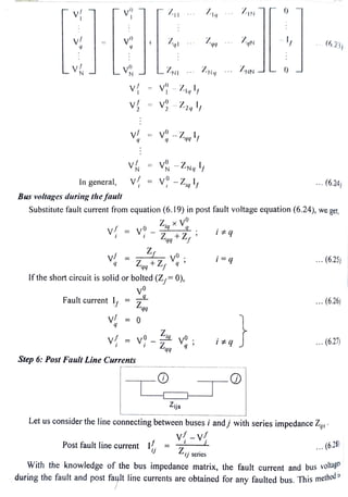
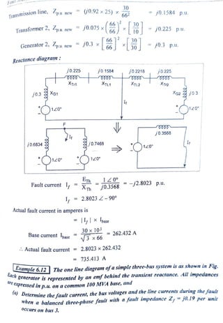
![Example 6.10 A symmetrical fault occurs on bus 4 of system shown in Fig.
Determine the fuult current, postfault voltages and line crrents.
Lous
Zyus
Transformer : Xteak
G, G, : 100 MVA, 20KV, X* 15%
1
Ly, L, : Xt= 10%
OSolution: Step l: Draw reactance diagram.
j0.15
= I[j0.15]
j0.09
120°
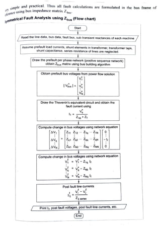
Step 2:Form Z-bus using bus building algorithm.
j0.15
2
9%
[j0.15 0.15
2Lj0.15 j0.24.
L
j0.09
Ly
j0.15
j0.1
j0.1
j0.05
3
j0.09
j0.09
-
1
j0.15
120°
4
j0.09
0000
j0.15
j0.15](https://image.slidesharecdn.com/faultanalysisusingzbus-231005161855-d335542e/85/Fault-Analysis-using-Z-Bus-pdf-6-320.jpg)
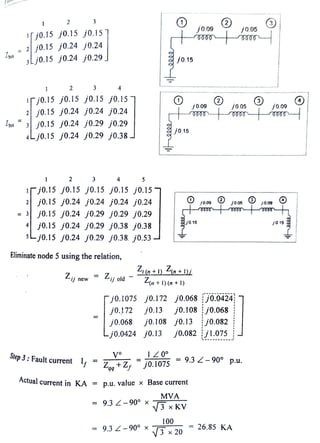
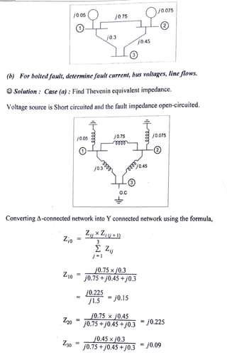
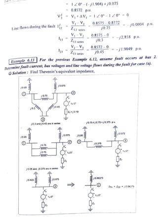
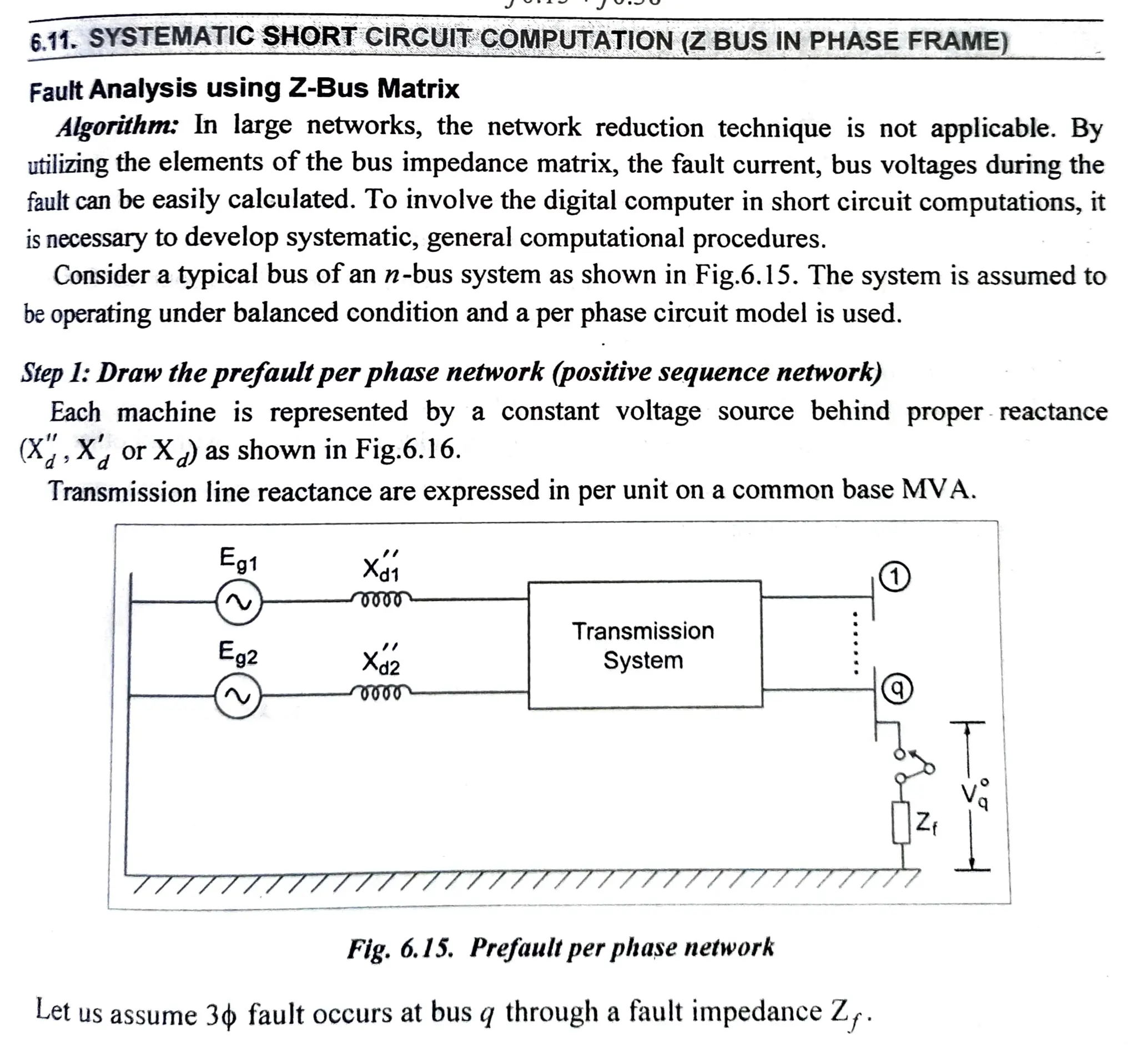
![Faultcurrent I,
Current contribution by generators:
Bus voltages & Line flows :
From Fig.1,
V
Current contribution by generator 1, lG =
=
I3 =
V.
10°
j0.06375 +
j0.19
jO.05 +j0.375]
Current contributed by generator 2, IG2 = (-j3.94) x j0.05 +j0.375 +j0.075
L3=
j0 05
VË-V2
j0.375
= Vpt t AV, = 120°-lGË xZi0
Z=j1,9|I
Z12 series
= 120° -(-j0.591) xj0.05 = 0.97 p.u.
V;-V,
-j3.94 p.u.
Z3 serics
2
p.rtAV = l20°- I XZn
I,xj0.075
j0.05 +j0.375 +j0.075
-j3.94xj0.03 - -j0.591 p.u.
=
j0.5
= -j3.349 p.u.
= |20°-(-j3.349) xj0.075 = 0.7488 p.u.
0.97-0.7488
j0.75
lG-I2 = -j0.591 -(-j0.295) = -j0.296 p.u.
Vi3 = I3x Z13 series =-j0.296 xj0.3 = 0.089 p.u.
j0075
0.7488-0.881
j0.45
v{ = V-Vi3 = 0.97-0.089 = 0.881 p.u.
-j0.295 p.u.
= j0.294 p.u.](https://image.slidesharecdn.com/faultanalysisusingzbus-231005161855-d335542e/85/Fault-Analysis-using-Z-Bus-pdf-14-320.jpg)