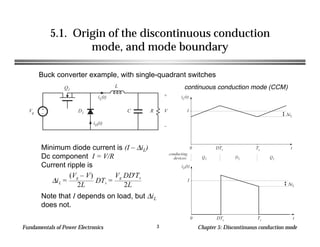
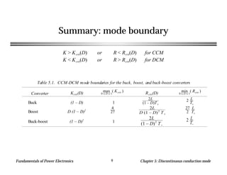
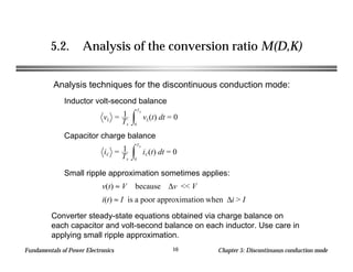
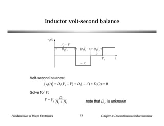
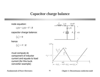
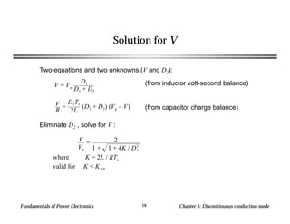
Fundamentals of Power Electronics Chapter 5: Discontinuous conduction mode1
Chapter 5. The Discontinuous Conduction Mode
5.1. Origin of the discontinuous conduction mode, and
mode boundary
5.2. Analysis of the conversion ratio M(D,K)
5.3. Boost converter example
5.4. Summary of results and key points
Fundamentals of Power Electronics Chapter 5: Discontinuous conduction mode2
Introduction to
Discontinuous Conduction Mode (DCM)
q Occurs because switching ripple in inductor current or capacitor voltage
causes polarity of applied switch current or voltage to reverse, such
that the current- or voltage-unidirectional assumptions made in realizing
the switch are violated.
q Commonly occurs in dc-dc converters and rectifiers, having single-
quadrant switches. May also occur in converters having two-quadrant
switches.
q Typical example: dc-dc converter operating at light load (small load
current). Sometimes, dc-dc converters and rectifiers are purposely
designed to operate in DCM at all loads.
q Properties of converters change radically when DCM is entered:
M becomes load-dependent
Output impedance is increased
Dynamics are altered
Control of output voltage may be lost when load is removed
Fundamentals of Power Electronics Chapter 5: Discontinuous conduction mode3
5.1. Origin of the discontinuous conduction
mode, and mode boundary
Buck converter example, with single-quadrant switches
+
–
Q1
L
C R
+
V
–
D1Vg
iL(t)
iD(t)
iL(t)
t
∆iL
I
0 DTs Ts
conducting
devices: Q1 D1 Q1
iD(t)
t0 DTs Ts
∆iL
I∆iL =
(Vg – V)
2L
DTs =
Vg DD'Ts
2L
continuous conduction mode (CCM)
Minimum diode current is (I – ∆iL)
Dc component I = V/R
Current ripple is
Note that I depends on load, but ∆iL
does not.
Fundamentals of Power Electronics Chapter 5: Discontinuous conduction mode4
Reduction of load current
Increase R, until I = ∆iL
+
–
Q1
L
C R
+
V
–
D1Vg
iL(t)
iD(t)
∆iL =
(Vg – V)
2L
DTs =
Vg DD'Ts
2L
CCM-DCM boundary
Minimum diode current is (I – ∆iL)
Dc component I = V/R
Current ripple is
Note that I depends on load, but ∆iL
does not.
iL(t)
t0 DTs Ts
conducting
devices: Q1 D1 Q1
∆iL
I
iD(t)
t0 DTs Ts
I
∆iL
Fundamentals of Power Electronics Chapter 5: Discontinuous conduction mode5
Further reduce load current
Increase R some more, such that I < ∆iL
+
–
Q1
L
C R
+
V
–
D1Vg
iL(t)
iD(t)
∆iL =
(Vg – V)
2L
DTs =
Vg DD'Ts
2L
Discontinuous conduction mode
Minimum diode current is (I – ∆iL)
Dc component I = V/R
Current ripple is
Note that I depends on load, but ∆iL
does not.
The load current continues to be
positive and non-zero.
iL(t)
t0 DTs Ts
conducting
devices: Q1 D1
Q1
I
X
D1Ts D2Ts D3Ts
iD(t)
t0 DTs Ts
D2Ts
Fundamentals of Power Electronics Chapter 5: Discontinuous conduction mode6
Mode boundary
I > ∆iL for CCM
I < ∆iL for DCM
Insert buck converter expressions for I and ∆iL :
DVg
R
<
DD'TsVg
2L
2L
RTs
< D'
Simplify:
This expression is of the form
K < Kcrit(D) for DCM
where K = 2L
RTs
and Kcrit(D) = D'
Fundamentals of Power Electronics Chapter 5: Discontinuous conduction mode7
K and Kcrit vs. D
Kcrit(D) = 1 – D
0 D1
0
1
2
K = 2L/RTs
K < Kcrit:
DCM
K > Kcrit:
CCM
Kcrit(D) = 1 – D
0 D1
0
1
2
K = 2L/RTs
K > Kcrit:
CCM
for K < 1: for K > 1:
Fundamentals of Power Electronics Chapter 5: Discontinuous conduction mode8
Critical load resistance Rcrit
R < Rcrit(D) for CCM
R > Rcrit(D) for DCM
where Rcrit(D) = 2L
D'Ts
Solve Kcrit equation for load resistance R:
Fundamentals of Power Electronics Chapter 5: Discontinuous conduction mode9
Summary: mode boundary
K > Kcrit(D) or R < Rcrit(D) for CCM
K < Kcrit(D) or R > Rcrit(D) for DCM
Table 5.1. CCM-DCM mode boundaries for the buck, boost, and buck-boost converters
Converter Kcrit(D) max
0 ≤ D ≤ 1
( Kcrit )
Rcrit(D) min
0 ≤ D ≤ 1
( Rcrit )
Buck (1 – D) 1
2L
(1 – D)T s
2 L
Ts
Boost D (1 – D)2
4
27
2L
D (1 – D)2
T s
27
2
L
Ts
Buck-boost (1 – D)2
1
2L
(1 – D)2
T s
2 L
Ts
Fundamentals of Power Electronics Chapter 5: Discontinuous conduction mode10
5.2. Analysis of the conversion ratio M(D,K)
Inductor volt-second balance
Analysis techniques for the discontinuous conduction mode:
vL = 1
Ts
vL(t) dt
0
Ts
= 0
Capacitor charge balance
iC = 1
Ts
iC(t) dt
0
Ts
= 0
Small ripple approximation sometimes applies:
v(t) ≈ V because ∆v << V
i(t) ≈ I is a poor approximation when ∆i > I
Converter steady-state equations obtained via charge balance on
each capacitor and volt-second balance on each inductor. Use care in
applying small ripple approximation.
Fundamentals of Power Electronics Chapter 5: Discontinuous conduction mode11
Example: Analysis of
DCM buck converter M(D,K)
+
–
Q1
L
C R
+
V
–
D1Vg
iL(t)
iD(t)
+
–
Vg
L
C R
+
v(t)
–
iC(t)+ vL(t) –
iL(t)
+
–
Vg
L
C R
+
v(t)
–
iC(t)+ vL(t) –
iL(t)
+
–
Vg
L
C R
+
v(t)
–
iC(t)+ vL(t) –
iL(t)
subinterval 1
subinterval 2
subinterval 3
Fundamentals of Power Electronics Chapter 5: Discontinuous conduction mode12
Subinterval 1
+
–
Vg
L
C R
+
v(t)
–
iC(t)+ vL(t) –
iL(t)
vL(t) = Vg – v(t)
iC(t) = iL(t) – v(t) / R
vL(t) ≈ Vg – V
iC(t) ≈ iL(t) – V / R
Small ripple approximation
for v(t) (but not for i(t)!):
Fundamentals of Power Electronics Chapter 5: Discontinuous conduction mode13
Subinterval 2
Small ripple approximation
for v(t) but not for i(t):
+
–
Vg
L
C R
+
v(t)
–
iC(t)+ vL(t) –
iL(t)
vL(t) = – v(t)
iC(t) = iL(t) – v(t) / R
vL(t) ≈ – V
iC(t) ≈ iL(t) – V / R
Fundamentals of Power Electronics Chapter 5: Discontinuous conduction mode14
Subinterval 3
+
–
Vg
L
C R
+
v(t)
–
iC(t)+ vL(t) –
iL(t)
vL = 0, iL = 0
iC(t) = iL(t) – v(t) / R
Small ripple approximation:
vL(t) = 0
iC(t) = – V / R
Fundamentals of Power Electronics Chapter 5: Discontinuous conduction mode15
Inductor volt-second balance
vL(t)
0
Ts t
D1Ts D2Ts D3Ts
Vg – V
– V
Volt-second balance:
Solve for V:
vL(t) = D1(Vg – V) + D2( – V) + D3(0) = 0
V = Vg
D1
D1 + D2
note that D2 is unknown
Fundamentals of Power Electronics Chapter 5: Discontinuous conduction mode16
Capacitor charge balance
iL(t)
t0 DTs Ts
D1Ts D2Ts D3Ts
<iL> = I
ipk
Vg – V
L – V
L
L
C R
+
v(t)
–
iC(t)
iL(t) v(t)/Rnode equation:
iL(t) = iC(t) + V / R
capacitor charge balance:
iC = 0
hence
iL = V / R
must compute dc
component of inductor
current and equate to load
current (for this buck
converter example)
Fundamentals of Power Electronics Chapter 5: Discontinuous conduction mode17
Inductor current waveform
iL(t)
t0 DTs Ts
D1Ts D2Ts D3Ts
<iL> = I
ipk
Vg – V
L – V
L
peak current:
iL(D1Ts) = ipk =
Vg – V
L
D1Ts
average current:
iL = 1
Ts
iL(t) dt
0
Ts
triangle area formula:
iL(t) dt
0
Ts
= 1
2
ipk (D1 + D2)Ts
iL = (Vg – V)
D1Ts
2L
(D1 + D2)
equate dc component to dc load current:
V
R
=
D1Ts
2L
(D1 + D2) (Vg – V)
Fundamentals of Power Electronics Chapter 5: Discontinuous conduction mode18
Solution for V
Two equations and two unknowns (V and D2):
V = Vg
D1
D1 + D2
V
R
=
D1Ts
2L
(D1 + D2) (Vg – V)
(from inductor volt-second balance)
(from capacitor charge balance)
Eliminate D2 , solve for V :
V
Vg
= 2
1 + 1 + 4K / D1
2
where K = 2L / RTs
valid for K < Kcrit
Fundamentals of Power Electronics Chapter 5: Discontinuous conduction mode19
Buck converter M(D,K)
0.0
0.2
0.4
0.6
0.8
1.0
M(D,K)
0.0 0.2 0.4 0.6 0.8 1.0
D
K = 0.01
K = 0.1
K = 0.5
K ≥ 1
M =
D for K > Kcrit
2
1 + 1 + 4K / D2
for K < Kcrit
Fundamentals of Power Electronics Chapter 5: Discontinuous conduction mode20
5.3. Boost converter example
+
–
Q1
L
C R
+
v(t)
–
D1
Vg
i(t)
+ vL(t) –
iD(t)
iC(t)
I > ∆iL for CCM
I < ∆iL for DCM
I =
Vg
D'2
R
∆iL =
Vg
2L
DTs
Previous CCM soln:Mode boundary:
Fundamentals of Power Electronics Chapter 5: Discontinuous conduction mode21
Mode boundary
Vg
D'2
R
>
DTsVg
2L
for CCM
2L
RTs
> DD'2
for CCM
0
0.05
0.1
0.15
Kcrit(D)
0 0.2 0.4 0.6 0.8 1
D
Kcrit(1
3) = 4
27
K > Kcrit(D) for CCM
K < Kcrit(D) for DCM
where K = 2L
RTs
and Kcrit(D) = DD'2
Fundamentals of Power Electronics Chapter 5: Discontinuous conduction mode22
Mode boundary
0
0.05
0.1
0.15
Kcrit
(D)
0 0.2 0.4 0.6 0.8 1
D
K
K < Kcrit
DCM CCM
K > Kcrit
CCM
K > Kcrit(D) for CCM
K < Kcrit(D) for DCM
where K = 2L
RTs
and Kcrit(D) = DD'2
Fundamentals of Power Electronics Chapter 5: Discontinuous conduction mode23
Conversion ratio: DCM boost
subinterval 1
subinterval 2
subinterval 3
+
–
Q1
L
C R
+
v(t)
–
D1
Vg
i(t)
+ vL(t) –
iD(t)
iC(t)
C R
+
v(t)
–
iC(t)
+
–
L
Vg
i(t)
+ vL(t) –
C R
+
v(t)
–
iC(t)
+
–
L
Vg
i(t)
+ vL(t) –
C R
+
v(t)
–
iC(t)
+
–
L
Vg
i(t)
+ vL(t) –
Fundamentals of Power Electronics Chapter 5: Discontinuous conduction mode24
Subinterval 1
Small ripple approximation
for v(t) (but not for i(t)!):
C R
+
v(t)
–
iC(t)
+
–
L
Vg
i(t)
+ vL(t) –
vL(t) = Vg
iC(t) = – v(t) / R
vL(t) ≈ Vg
iC(t) ≈ – V / R 0 < t < D1Ts
Fundamentals of Power Electronics Chapter 5: Discontinuous conduction mode25
Subinterval 2
Small ripple approximation
for v(t) but not for i(t):
D1Ts < t < (D1 +D2)Ts
C R
+
v(t)
–
iC(t)
+
–
L
Vg
i(t)
+ vL(t) –
vL(t) = Vg – v(t)
iC(t) = i(t) – v(t) / R
vL(t) ≈ Vg – V
iC(t) ≈ i(t) – V / R
Fundamentals of Power Electronics Chapter 5: Discontinuous conduction mode26
Subinterval 3
Small ripple approximation:
(D1 +D2)Ts < t < Ts
C R
+
v(t)
–
iC(t)
+
–
L
Vg
i(t)
+ vL(t) –
vL = 0, i = 0
iC(t) = – v(t) / R
vL(t) = 0
iC(t) = – V / R
Fundamentals of Power Electronics Chapter 5: Discontinuous conduction mode27
Inductor volt-second balance
Volt-second balance:
Solve for V:
note that D2 is unknown
vL(t)
0
Ts t
D1Ts D2Ts D3Ts
Vg
Vg – V
D1Vg + D2(Vg – V) + D3(0) = 0
V =
D1 + D2
D2
Vg
Fundamentals of Power Electronics Chapter 5: Discontinuous conduction mode28
Capacitor charge balance
node equation:
capacitor charge balance:
iC = 0
hence
must compute dc component of diode
current and equate to load current
(for this boost converter example)
C R
+
v(t)
–
D1 iD(t)
iC(t)
iD(t) = iC(t) + v(t) / R
iD = V / R
Fundamentals of Power Electronics Chapter 5: Discontinuous conduction mode29
Inductor and diode current waveforms
peak current:
average diode current:
triangle area formula:
i(t)
t0 DTs Ts
D1Ts D2Ts D3Ts
ipk
Vg – V
L
Vg
L
iD(t)
t0 DTs Ts
D1Ts D2Ts D3Ts
ipk
Vg – V
L
<iD>
ipk =
Vg
L
D1Ts
iD = 1
Ts
iD(t) dt
0
Ts
iD(t) dt
0
Ts
= 1
2
ipk D2Ts
Fundamentals of Power Electronics Chapter 5: Discontinuous conduction mode30
Equate diode current to load current
iD = 1
Ts
1
2
ipk D2Ts =
VgD1D2Ts
2L
average diode current:
equate to dc load current:
VgD1D2Ts
2L
= V
R
Fundamentals of Power Electronics Chapter 5: Discontinuous conduction mode31
Solution for V
Two equations and two unknowns (V and D2):
(from inductor volt-second balance)
(from capacitor charge balance)
Eliminate D2 , solve for V. From volt-sec balance eqn:
V =
D1 + D2
D2
Vg
VgD1D2Ts
2L
= V
R
D2 = D1
Vg
V – Vg
Substitute into charge balance eqn, rearrange terms:
V2
– VVg –
Vg
2
D1
2
K
= 0
Fundamentals of Power Electronics Chapter 5: Discontinuous conduction mode32
Solution for V
V2
– VVg –
Vg
2
D1
2
K
= 0
Use quadratic formula:
V
Vg
=
1 ± 1 + 4D1
2
/ K
2
Note that one root leads to positive V, while other leads to
negative V. Select positive root:
V
Vg
= M(D1,K) =
1 + 1 + 4D1
2
/ K
2
where K = 2L / RTs
valid for K < Kcrit(D)
Transistor duty cycle D = interval 1 duty cycle D1
Fundamentals of Power Electronics Chapter 5: Discontinuous conduction mode33
Boost converter characteristics
M ≈ 1
2
+ D
K
0
1
2
3
4
5
M(D,K)
0 0.25 0.5 0.75 1
D
K=0.01
K
=
0.05
K = 0.1
K ≥ 4/27
Approximate M in DCM:
M =
1
1 – D
for K > Kcrit
1 + 1 + 4D2
/ K
2
for K < Kcrit
Fundamentals of Power Electronics Chapter 5: Discontinuous conduction mode34
Summary of DCM characteristics
Table 5.2. Summary of CCM-DCM characteristics for the buck, boost, and buck-boost converters
Converter Kcrit(D) DCM M(D,K) DCM D2(D,K) CCM M(D)
Buck (1 – D)
2
1 + 1 + 4K / D2
K
D
M(D,K) D
Boost D (1 – D)2 1 + 1 + 4D2
/ K
2
K
D
M(D,K) 1
1 – D
Buck-boost (1 – D)2 – D
K K – D
1 – D
with K = 2L / RTs. DCM occurs for K < Kcrit.
Fundamentals of Power Electronics Chapter 5: Discontinuous conduction mode35
Summary of DCM characteristics
0
1
0 0.2 0.4 0.6 0.8 1
D
Boost
Buck
Buck-boost (× –1)
DCM
M(D,K)
1
K
• DCM buck and boost
characteristics are
asymptotic to M = 1 and to
the DCM buck-boost
characteristic
• DCM buck-boost
characteristic is linear
• CCM and DCM
characteristics intersect at
mode boundary. Actual M
follows characteristic
having larger magnitude
• DCM boost characteristic is
nearly linear
Fundamentals of Power Electronics Chapter 5: Discontinuous conduction mode36
Summary of key points
1. The discontinuous conduction mode occurs in converters
containing current- or voltage-unidirectional switches, when the
inductor current or capacitor voltage ripple is large enough to
cause the switch current or voltage to reverse polarity.
2. Conditions for operation in the discontinuous conduction mode
can be found by determining when the inductor current or
capacitor voltage ripples and dc components cause the switch
on-state current or off-state voltage to reverse polarity.
3. The dc conversion ratio M of converters operating in the
discontinuous conduction mode can be found by application of
the principles of inductor volt-second and capacitor charge
balance.
Fundamentals of Power Electronics Chapter 5: Discontinuous conduction mode37
Summary of key points
4. Extra care is required when applying the small-ripple
approximation. Some waveforms, such as the output voltage,
should have small ripple which can be neglected. Other
waveforms, such as one or more inductor currents, may have
large ripple that cannot be ignored.
5. The characteristics of a converter changes significantly when
the converter enters DCM. The output voltage becomes load-
dependent, resulting in an increase in the converter output
impedance.

Chapter 05

  • 1.
    Fundamentals of PowerElectronics Chapter 5: Discontinuous conduction mode1 Chapter 5. The Discontinuous Conduction Mode 5.1. Origin of the discontinuous conduction mode, and mode boundary 5.2. Analysis of the conversion ratio M(D,K) 5.3. Boost converter example 5.4. Summary of results and key points
  • 2.
    Fundamentals of PowerElectronics Chapter 5: Discontinuous conduction mode2 Introduction to Discontinuous Conduction Mode (DCM) q Occurs because switching ripple in inductor current or capacitor voltage causes polarity of applied switch current or voltage to reverse, such that the current- or voltage-unidirectional assumptions made in realizing the switch are violated. q Commonly occurs in dc-dc converters and rectifiers, having single- quadrant switches. May also occur in converters having two-quadrant switches. q Typical example: dc-dc converter operating at light load (small load current). Sometimes, dc-dc converters and rectifiers are purposely designed to operate in DCM at all loads. q Properties of converters change radically when DCM is entered: M becomes load-dependent Output impedance is increased Dynamics are altered Control of output voltage may be lost when load is removed
  • 3.
    Fundamentals of PowerElectronics Chapter 5: Discontinuous conduction mode3 5.1. Origin of the discontinuous conduction mode, and mode boundary Buck converter example, with single-quadrant switches + – Q1 L C R + V – D1Vg iL(t) iD(t) iL(t) t ∆iL I 0 DTs Ts conducting devices: Q1 D1 Q1 iD(t) t0 DTs Ts ∆iL I∆iL = (Vg – V) 2L DTs = Vg DD'Ts 2L continuous conduction mode (CCM) Minimum diode current is (I – ∆iL) Dc component I = V/R Current ripple is Note that I depends on load, but ∆iL does not.
  • 4.
    Fundamentals of PowerElectronics Chapter 5: Discontinuous conduction mode4 Reduction of load current Increase R, until I = ∆iL + – Q1 L C R + V – D1Vg iL(t) iD(t) ∆iL = (Vg – V) 2L DTs = Vg DD'Ts 2L CCM-DCM boundary Minimum diode current is (I – ∆iL) Dc component I = V/R Current ripple is Note that I depends on load, but ∆iL does not. iL(t) t0 DTs Ts conducting devices: Q1 D1 Q1 ∆iL I iD(t) t0 DTs Ts I ∆iL
  • 5.
    Fundamentals of PowerElectronics Chapter 5: Discontinuous conduction mode5 Further reduce load current Increase R some more, such that I < ∆iL + – Q1 L C R + V – D1Vg iL(t) iD(t) ∆iL = (Vg – V) 2L DTs = Vg DD'Ts 2L Discontinuous conduction mode Minimum diode current is (I – ∆iL) Dc component I = V/R Current ripple is Note that I depends on load, but ∆iL does not. The load current continues to be positive and non-zero. iL(t) t0 DTs Ts conducting devices: Q1 D1 Q1 I X D1Ts D2Ts D3Ts iD(t) t0 DTs Ts D2Ts
  • 6.
    Fundamentals of PowerElectronics Chapter 5: Discontinuous conduction mode6 Mode boundary I > ∆iL for CCM I < ∆iL for DCM Insert buck converter expressions for I and ∆iL : DVg R < DD'TsVg 2L 2L RTs < D' Simplify: This expression is of the form K < Kcrit(D) for DCM where K = 2L RTs and Kcrit(D) = D'
  • 7.
    Fundamentals of PowerElectronics Chapter 5: Discontinuous conduction mode7 K and Kcrit vs. D Kcrit(D) = 1 – D 0 D1 0 1 2 K = 2L/RTs K < Kcrit: DCM K > Kcrit: CCM Kcrit(D) = 1 – D 0 D1 0 1 2 K = 2L/RTs K > Kcrit: CCM for K < 1: for K > 1:
  • 8.
    Fundamentals of PowerElectronics Chapter 5: Discontinuous conduction mode8 Critical load resistance Rcrit R < Rcrit(D) for CCM R > Rcrit(D) for DCM where Rcrit(D) = 2L D'Ts Solve Kcrit equation for load resistance R:
  • 9.
    Fundamentals of PowerElectronics Chapter 5: Discontinuous conduction mode9 Summary: mode boundary K > Kcrit(D) or R < Rcrit(D) for CCM K < Kcrit(D) or R > Rcrit(D) for DCM Table 5.1. CCM-DCM mode boundaries for the buck, boost, and buck-boost converters Converter Kcrit(D) max 0 ≤ D ≤ 1 ( Kcrit ) Rcrit(D) min 0 ≤ D ≤ 1 ( Rcrit ) Buck (1 – D) 1 2L (1 – D)T s 2 L Ts Boost D (1 – D)2 4 27 2L D (1 – D)2 T s 27 2 L Ts Buck-boost (1 – D)2 1 2L (1 – D)2 T s 2 L Ts
  • 10.
    Fundamentals of PowerElectronics Chapter 5: Discontinuous conduction mode10 5.2. Analysis of the conversion ratio M(D,K) Inductor volt-second balance Analysis techniques for the discontinuous conduction mode: vL = 1 Ts vL(t) dt 0 Ts = 0 Capacitor charge balance iC = 1 Ts iC(t) dt 0 Ts = 0 Small ripple approximation sometimes applies: v(t) ≈ V because ∆v << V i(t) ≈ I is a poor approximation when ∆i > I Converter steady-state equations obtained via charge balance on each capacitor and volt-second balance on each inductor. Use care in applying small ripple approximation.
  • 11.
    Fundamentals of PowerElectronics Chapter 5: Discontinuous conduction mode11 Example: Analysis of DCM buck converter M(D,K) + – Q1 L C R + V – D1Vg iL(t) iD(t) + – Vg L C R + v(t) – iC(t)+ vL(t) – iL(t) + – Vg L C R + v(t) – iC(t)+ vL(t) – iL(t) + – Vg L C R + v(t) – iC(t)+ vL(t) – iL(t) subinterval 1 subinterval 2 subinterval 3
  • 12.
    Fundamentals of PowerElectronics Chapter 5: Discontinuous conduction mode12 Subinterval 1 + – Vg L C R + v(t) – iC(t)+ vL(t) – iL(t) vL(t) = Vg – v(t) iC(t) = iL(t) – v(t) / R vL(t) ≈ Vg – V iC(t) ≈ iL(t) – V / R Small ripple approximation for v(t) (but not for i(t)!):
  • 13.
    Fundamentals of PowerElectronics Chapter 5: Discontinuous conduction mode13 Subinterval 2 Small ripple approximation for v(t) but not for i(t): + – Vg L C R + v(t) – iC(t)+ vL(t) – iL(t) vL(t) = – v(t) iC(t) = iL(t) – v(t) / R vL(t) ≈ – V iC(t) ≈ iL(t) – V / R
  • 14.
    Fundamentals of PowerElectronics Chapter 5: Discontinuous conduction mode14 Subinterval 3 + – Vg L C R + v(t) – iC(t)+ vL(t) – iL(t) vL = 0, iL = 0 iC(t) = iL(t) – v(t) / R Small ripple approximation: vL(t) = 0 iC(t) = – V / R
  • 15.
    Fundamentals of PowerElectronics Chapter 5: Discontinuous conduction mode15 Inductor volt-second balance vL(t) 0 Ts t D1Ts D2Ts D3Ts Vg – V – V Volt-second balance: Solve for V: vL(t) = D1(Vg – V) + D2( – V) + D3(0) = 0 V = Vg D1 D1 + D2 note that D2 is unknown
  • 16.
    Fundamentals of PowerElectronics Chapter 5: Discontinuous conduction mode16 Capacitor charge balance iL(t) t0 DTs Ts D1Ts D2Ts D3Ts <iL> = I ipk Vg – V L – V L L C R + v(t) – iC(t) iL(t) v(t)/Rnode equation: iL(t) = iC(t) + V / R capacitor charge balance: iC = 0 hence iL = V / R must compute dc component of inductor current and equate to load current (for this buck converter example)
  • 17.
    Fundamentals of PowerElectronics Chapter 5: Discontinuous conduction mode17 Inductor current waveform iL(t) t0 DTs Ts D1Ts D2Ts D3Ts <iL> = I ipk Vg – V L – V L peak current: iL(D1Ts) = ipk = Vg – V L D1Ts average current: iL = 1 Ts iL(t) dt 0 Ts triangle area formula: iL(t) dt 0 Ts = 1 2 ipk (D1 + D2)Ts iL = (Vg – V) D1Ts 2L (D1 + D2) equate dc component to dc load current: V R = D1Ts 2L (D1 + D2) (Vg – V)
  • 18.
    Fundamentals of PowerElectronics Chapter 5: Discontinuous conduction mode18 Solution for V Two equations and two unknowns (V and D2): V = Vg D1 D1 + D2 V R = D1Ts 2L (D1 + D2) (Vg – V) (from inductor volt-second balance) (from capacitor charge balance) Eliminate D2 , solve for V : V Vg = 2 1 + 1 + 4K / D1 2 where K = 2L / RTs valid for K < Kcrit
  • 19.
    Fundamentals of PowerElectronics Chapter 5: Discontinuous conduction mode19 Buck converter M(D,K) 0.0 0.2 0.4 0.6 0.8 1.0 M(D,K) 0.0 0.2 0.4 0.6 0.8 1.0 D K = 0.01 K = 0.1 K = 0.5 K ≥ 1 M = D for K > Kcrit 2 1 + 1 + 4K / D2 for K < Kcrit
  • 20.
    Fundamentals of PowerElectronics Chapter 5: Discontinuous conduction mode20 5.3. Boost converter example + – Q1 L C R + v(t) – D1 Vg i(t) + vL(t) – iD(t) iC(t) I > ∆iL for CCM I < ∆iL for DCM I = Vg D'2 R ∆iL = Vg 2L DTs Previous CCM soln:Mode boundary:
  • 21.
    Fundamentals of PowerElectronics Chapter 5: Discontinuous conduction mode21 Mode boundary Vg D'2 R > DTsVg 2L for CCM 2L RTs > DD'2 for CCM 0 0.05 0.1 0.15 Kcrit(D) 0 0.2 0.4 0.6 0.8 1 D Kcrit(1 3) = 4 27 K > Kcrit(D) for CCM K < Kcrit(D) for DCM where K = 2L RTs and Kcrit(D) = DD'2
  • 22.
    Fundamentals of PowerElectronics Chapter 5: Discontinuous conduction mode22 Mode boundary 0 0.05 0.1 0.15 Kcrit (D) 0 0.2 0.4 0.6 0.8 1 D K K < Kcrit DCM CCM K > Kcrit CCM K > Kcrit(D) for CCM K < Kcrit(D) for DCM where K = 2L RTs and Kcrit(D) = DD'2
  • 23.
    Fundamentals of PowerElectronics Chapter 5: Discontinuous conduction mode23 Conversion ratio: DCM boost subinterval 1 subinterval 2 subinterval 3 + – Q1 L C R + v(t) – D1 Vg i(t) + vL(t) – iD(t) iC(t) C R + v(t) – iC(t) + – L Vg i(t) + vL(t) – C R + v(t) – iC(t) + – L Vg i(t) + vL(t) – C R + v(t) – iC(t) + – L Vg i(t) + vL(t) –
  • 24.
    Fundamentals of PowerElectronics Chapter 5: Discontinuous conduction mode24 Subinterval 1 Small ripple approximation for v(t) (but not for i(t)!): C R + v(t) – iC(t) + – L Vg i(t) + vL(t) – vL(t) = Vg iC(t) = – v(t) / R vL(t) ≈ Vg iC(t) ≈ – V / R 0 < t < D1Ts
  • 25.
    Fundamentals of PowerElectronics Chapter 5: Discontinuous conduction mode25 Subinterval 2 Small ripple approximation for v(t) but not for i(t): D1Ts < t < (D1 +D2)Ts C R + v(t) – iC(t) + – L Vg i(t) + vL(t) – vL(t) = Vg – v(t) iC(t) = i(t) – v(t) / R vL(t) ≈ Vg – V iC(t) ≈ i(t) – V / R
  • 26.
    Fundamentals of PowerElectronics Chapter 5: Discontinuous conduction mode26 Subinterval 3 Small ripple approximation: (D1 +D2)Ts < t < Ts C R + v(t) – iC(t) + – L Vg i(t) + vL(t) – vL = 0, i = 0 iC(t) = – v(t) / R vL(t) = 0 iC(t) = – V / R
  • 27.
    Fundamentals of PowerElectronics Chapter 5: Discontinuous conduction mode27 Inductor volt-second balance Volt-second balance: Solve for V: note that D2 is unknown vL(t) 0 Ts t D1Ts D2Ts D3Ts Vg Vg – V D1Vg + D2(Vg – V) + D3(0) = 0 V = D1 + D2 D2 Vg
  • 28.
    Fundamentals of PowerElectronics Chapter 5: Discontinuous conduction mode28 Capacitor charge balance node equation: capacitor charge balance: iC = 0 hence must compute dc component of diode current and equate to load current (for this boost converter example) C R + v(t) – D1 iD(t) iC(t) iD(t) = iC(t) + v(t) / R iD = V / R
  • 29.
    Fundamentals of PowerElectronics Chapter 5: Discontinuous conduction mode29 Inductor and diode current waveforms peak current: average diode current: triangle area formula: i(t) t0 DTs Ts D1Ts D2Ts D3Ts ipk Vg – V L Vg L iD(t) t0 DTs Ts D1Ts D2Ts D3Ts ipk Vg – V L <iD> ipk = Vg L D1Ts iD = 1 Ts iD(t) dt 0 Ts iD(t) dt 0 Ts = 1 2 ipk D2Ts
  • 30.
    Fundamentals of PowerElectronics Chapter 5: Discontinuous conduction mode30 Equate diode current to load current iD = 1 Ts 1 2 ipk D2Ts = VgD1D2Ts 2L average diode current: equate to dc load current: VgD1D2Ts 2L = V R
  • 31.
    Fundamentals of PowerElectronics Chapter 5: Discontinuous conduction mode31 Solution for V Two equations and two unknowns (V and D2): (from inductor volt-second balance) (from capacitor charge balance) Eliminate D2 , solve for V. From volt-sec balance eqn: V = D1 + D2 D2 Vg VgD1D2Ts 2L = V R D2 = D1 Vg V – Vg Substitute into charge balance eqn, rearrange terms: V2 – VVg – Vg 2 D1 2 K = 0
  • 32.
    Fundamentals of PowerElectronics Chapter 5: Discontinuous conduction mode32 Solution for V V2 – VVg – Vg 2 D1 2 K = 0 Use quadratic formula: V Vg = 1 ± 1 + 4D1 2 / K 2 Note that one root leads to positive V, while other leads to negative V. Select positive root: V Vg = M(D1,K) = 1 + 1 + 4D1 2 / K 2 where K = 2L / RTs valid for K < Kcrit(D) Transistor duty cycle D = interval 1 duty cycle D1
  • 33.
    Fundamentals of PowerElectronics Chapter 5: Discontinuous conduction mode33 Boost converter characteristics M ≈ 1 2 + D K 0 1 2 3 4 5 M(D,K) 0 0.25 0.5 0.75 1 D K=0.01 K = 0.05 K = 0.1 K ≥ 4/27 Approximate M in DCM: M = 1 1 – D for K > Kcrit 1 + 1 + 4D2 / K 2 for K < Kcrit
  • 34.
    Fundamentals of PowerElectronics Chapter 5: Discontinuous conduction mode34 Summary of DCM characteristics Table 5.2. Summary of CCM-DCM characteristics for the buck, boost, and buck-boost converters Converter Kcrit(D) DCM M(D,K) DCM D2(D,K) CCM M(D) Buck (1 – D) 2 1 + 1 + 4K / D2 K D M(D,K) D Boost D (1 – D)2 1 + 1 + 4D2 / K 2 K D M(D,K) 1 1 – D Buck-boost (1 – D)2 – D K K – D 1 – D with K = 2L / RTs. DCM occurs for K < Kcrit.
  • 35.
    Fundamentals of PowerElectronics Chapter 5: Discontinuous conduction mode35 Summary of DCM characteristics 0 1 0 0.2 0.4 0.6 0.8 1 D Boost Buck Buck-boost (× –1) DCM M(D,K) 1 K • DCM buck and boost characteristics are asymptotic to M = 1 and to the DCM buck-boost characteristic • DCM buck-boost characteristic is linear • CCM and DCM characteristics intersect at mode boundary. Actual M follows characteristic having larger magnitude • DCM boost characteristic is nearly linear
  • 36.
    Fundamentals of PowerElectronics Chapter 5: Discontinuous conduction mode36 Summary of key points 1. The discontinuous conduction mode occurs in converters containing current- or voltage-unidirectional switches, when the inductor current or capacitor voltage ripple is large enough to cause the switch current or voltage to reverse polarity. 2. Conditions for operation in the discontinuous conduction mode can be found by determining when the inductor current or capacitor voltage ripples and dc components cause the switch on-state current or off-state voltage to reverse polarity. 3. The dc conversion ratio M of converters operating in the discontinuous conduction mode can be found by application of the principles of inductor volt-second and capacitor charge balance.
  • 37.
    Fundamentals of PowerElectronics Chapter 5: Discontinuous conduction mode37 Summary of key points 4. Extra care is required when applying the small-ripple approximation. Some waveforms, such as the output voltage, should have small ripple which can be neglected. Other waveforms, such as one or more inductor currents, may have large ripple that cannot be ignored. 5. The characteristics of a converter changes significantly when the converter enters DCM. The output voltage becomes load- dependent, resulting in an increase in the converter output impedance.