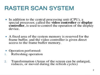
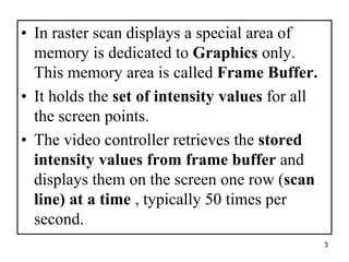
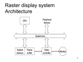
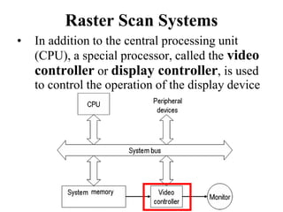
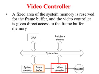
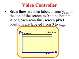
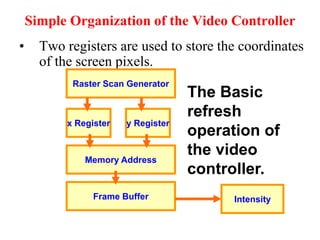
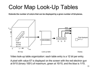
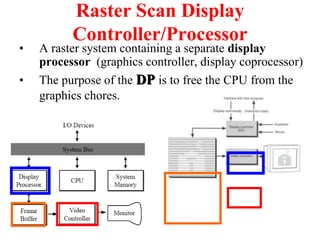
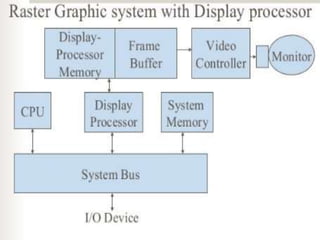
RASTER SCAN
DISPLAY SYSTEM
WITH
VIDEO CONTOLLER
1
2
• In raster scan displays a special area of
memory is dedicated to Graphics only.
This memory area is called Frame Buffer.
• It holds the set of intensity values for all
the screen points.
• The video controller retrieves the stored
intensity values from frame buffer and
displays them on the screen one row (scan
line) at a time , typically 50 times per
second.
3
Raster display system
Architecture
4
Raster Scan Systems
• In addition to the central processing unit
(CPU), a special processor, called the video
controller or display controller, is used
to control the operation of the display device.
Video Controller
• A fixed area of the system memory is reserved
for the frame buffer, and the video controller
is given direct access to the frame buffer
memory.
Video Controller
• Frame buffer location, and the
corresponding screen positions, are
referenced in Cartesian coordinates.
x
y
Video Controller
• Scan lines are then labeled from ymax at
the top of the screen to 0 at the bottom.
Along each scan line, screen pixel
positions are labeled from 0 to xmax.
Line Scan
y max
x max x
y Line Scan
y max
x max
Simple Organization of the Video Controller
• Two registers are used to store the coordinates
of the screen pixels.
Raster Scan Generator
x Register y Register
Memory Address
Frame Buffer Intensity
The Basic
refresh
operation of
the video
controller.
• In color displays, 24 bits per pixel are commonly used,
where 8 bits represent 256 levels for each color.
• It is necessary to read 24-bits for each pixel from frame
buffer. This is very time consuming.
• To avoid this video controller uses Look Up Table (LUT)
to store many entries of pixel values in RGB format.
• With this facility , now it is necessary to only read index
to the Look Up Table from the frame buffer for each
pixel.
• The specified entry in the Look Up Table is then used to
control the intensity or color of the CRT.
10
11
Color Map Look-Up Tables
Extends the number of colors that can be displayed by a given number of bit-planes.
0
1
0
0
0
0
1
1
67
100110100001
0
67
255
1001 1010 0001
R G B
RED
GREEN
BLUE
Pixel displayed
at x', y'
Pixel in
bit map
at x', y'
0 x
0
y
x
max
max
y
Bit map Look-up table Display
Video look-up table organization: each table entry is a 12 bit per entry.
A pixel with value 67 is displayed on the screen with the red electron gun
at 9/15 (binary 1001) of maximum, green at 10/15, and the blue is 1/15.
Raster Scan Display
System
with
Display Controller
Raster Scan Display
Controller/Processor
• A raster system containing a separate display
processor (graphics controller, display coprocessor)
• The purpose of the DP is to free the CPU from the
graphics chores.
Display processor
• Generation various line styles
(dashed, dotted, or solid)
• Displaying color areas
• Performing certain transformation
and manipulation on display
objects.
15
Random Scan Systems
Random Scan System
• Graphic commands are translated by the
graphics package into a display file stored in
the system memory.
• This file is then accessed by the display
processor unit (DPU)(graphic controller) to
refresh the screen.

Raster scan systems with video controller and display processor

  • 1.
  • 2.
  • 3.
    • In rasterscan displays a special area of memory is dedicated to Graphics only. This memory area is called Frame Buffer. • It holds the set of intensity values for all the screen points. • The video controller retrieves the stored intensity values from frame buffer and displays them on the screen one row (scan line) at a time , typically 50 times per second. 3
  • 4.
  • 5.
    Raster Scan Systems •In addition to the central processing unit (CPU), a special processor, called the video controller or display controller, is used to control the operation of the display device.
  • 6.
    Video Controller • Afixed area of the system memory is reserved for the frame buffer, and the video controller is given direct access to the frame buffer memory.
  • 7.
    Video Controller • Framebuffer location, and the corresponding screen positions, are referenced in Cartesian coordinates. x y
  • 8.
    Video Controller • Scanlines are then labeled from ymax at the top of the screen to 0 at the bottom. Along each scan line, screen pixel positions are labeled from 0 to xmax. Line Scan y max x max x y Line Scan y max x max
  • 9.
    Simple Organization ofthe Video Controller • Two registers are used to store the coordinates of the screen pixels. Raster Scan Generator x Register y Register Memory Address Frame Buffer Intensity The Basic refresh operation of the video controller.
  • 10.
    • In colordisplays, 24 bits per pixel are commonly used, where 8 bits represent 256 levels for each color. • It is necessary to read 24-bits for each pixel from frame buffer. This is very time consuming. • To avoid this video controller uses Look Up Table (LUT) to store many entries of pixel values in RGB format. • With this facility , now it is necessary to only read index to the Look Up Table from the frame buffer for each pixel. • The specified entry in the Look Up Table is then used to control the intensity or color of the CRT. 10
  • 11.
    11 Color Map Look-UpTables Extends the number of colors that can be displayed by a given number of bit-planes. 0 1 0 0 0 0 1 1 67 100110100001 0 67 255 1001 1010 0001 R G B RED GREEN BLUE Pixel displayed at x', y' Pixel in bit map at x', y' 0 x 0 y x max max y Bit map Look-up table Display Video look-up table organization: each table entry is a 12 bit per entry. A pixel with value 67 is displayed on the screen with the red electron gun at 9/15 (binary 1001) of maximum, green at 10/15, and the blue is 1/15.
  • 12.
  • 13.
    Raster Scan Display Controller/Processor •A raster system containing a separate display processor (graphics controller, display coprocessor) • The purpose of the DP is to free the CPU from the graphics chores.
  • 14.
    Display processor • Generationvarious line styles (dashed, dotted, or solid) • Displaying color areas • Performing certain transformation and manipulation on display objects.
  • 15.
  • 16.
  • 17.
    Random Scan System •Graphic commands are translated by the graphics package into a display file stored in the system memory. • This file is then accessed by the display processor unit (DPU)(graphic controller) to refresh the screen.