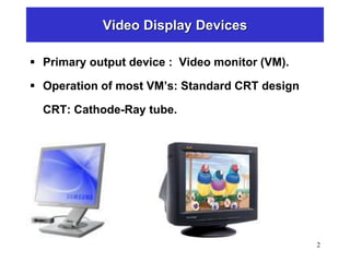
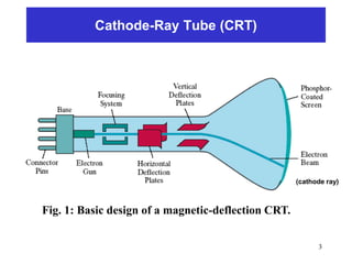
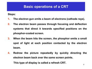
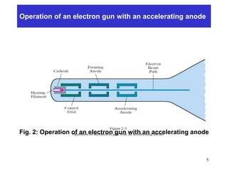
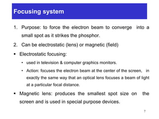
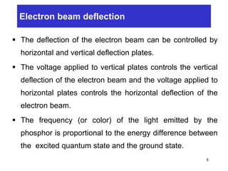
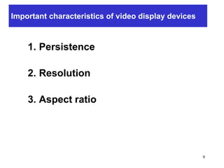
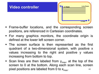
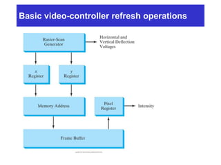
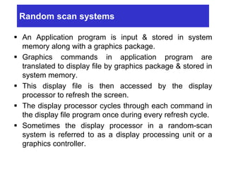
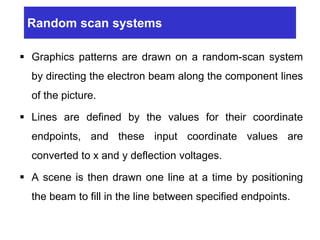
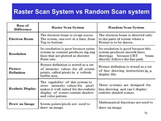
This document provides an overview of graphics display systems. It discusses the basic components and operation of cathode ray tube (CRT) displays, including the electron gun, focusing and deflection systems. It describes the refresh process of raster-scan CRTs and how random-scan CRTs work. Color CRT monitors are discussed, specifically the beam penetration and shadow mask methods. Key characteristics like resolution, persistence and aspect ratio are also summarized.


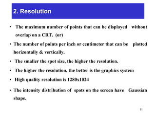


![제 23회 보아즈(BOAZ) 빅데이터 컨퍼런스 - [MBOAX] : ABSA를 활용한 소비자 반응 분석 기반 운영 효율화 대시보드 설계](https://cdn.slidesharecdn.com/ss_thumbnails/3-1boaz23rdconferencemboax-260203102709-9d519923-thumbnail.jpg?width=640&height=640&fit=bounds)


