Download to read offline

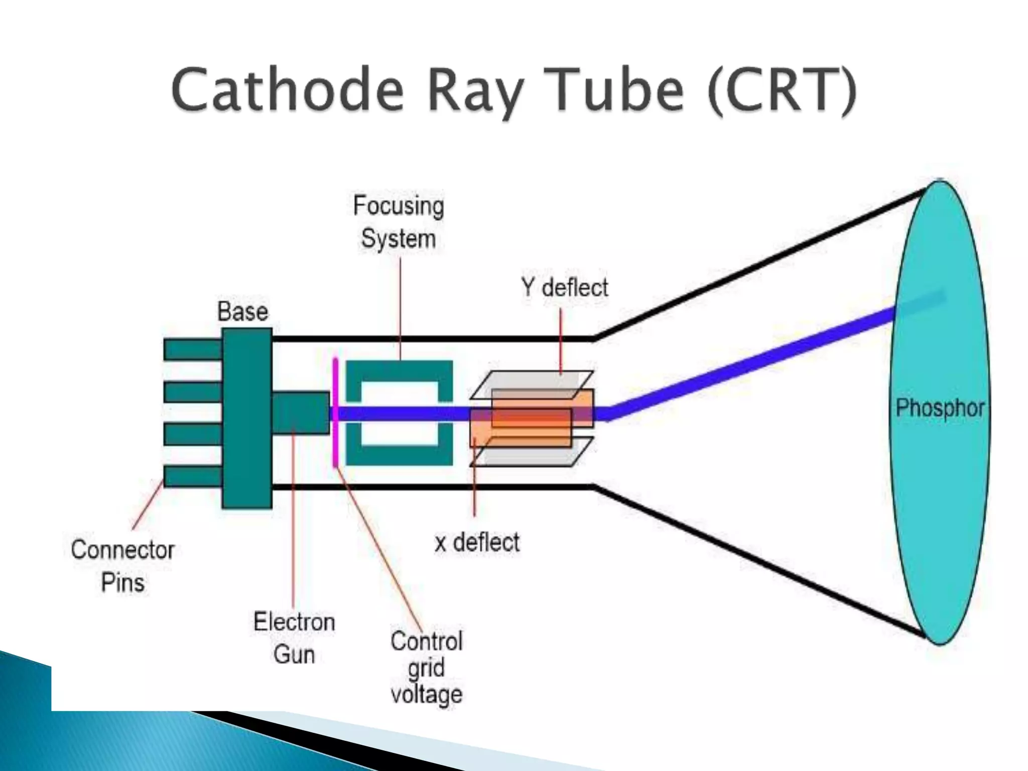

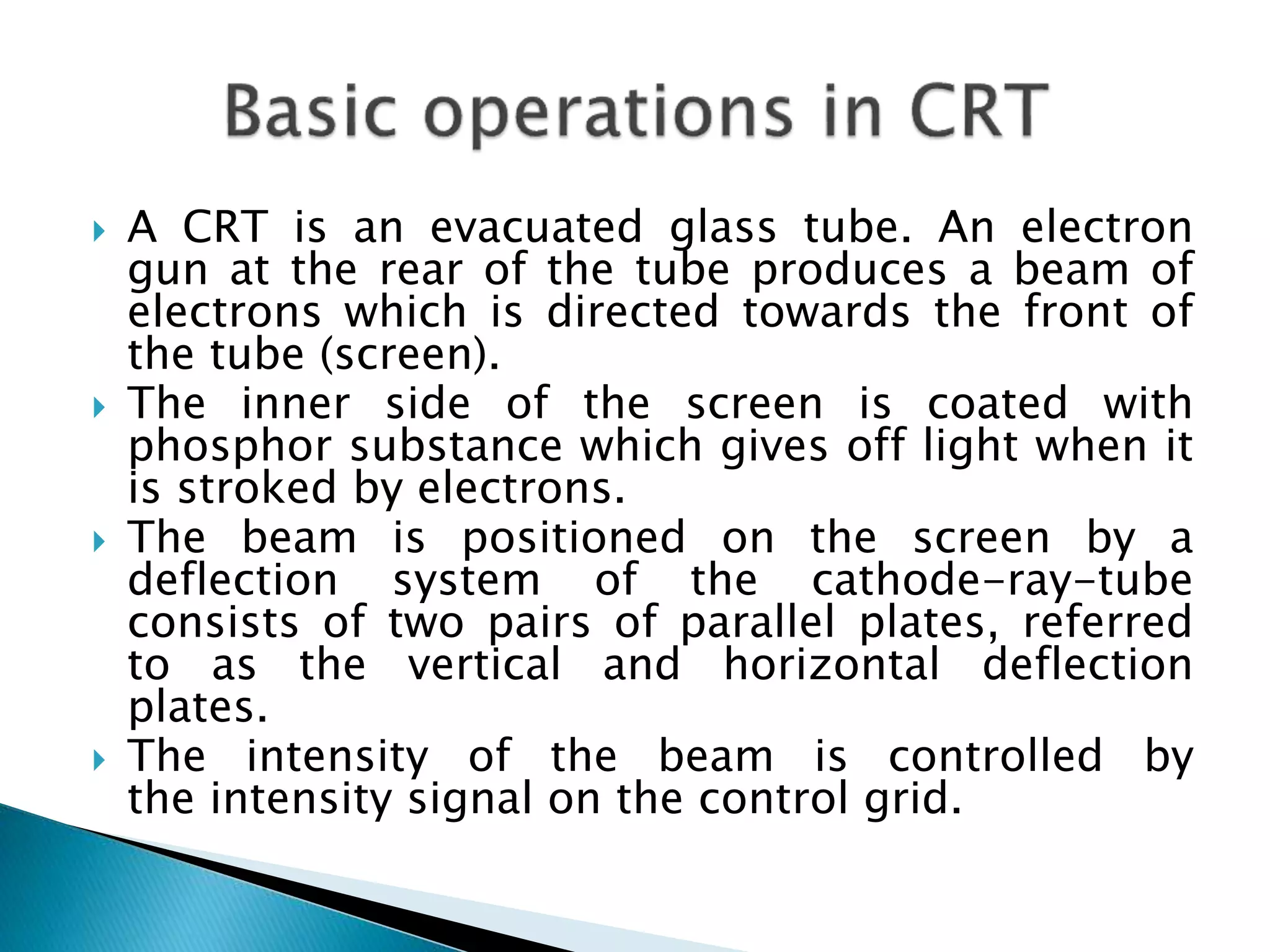
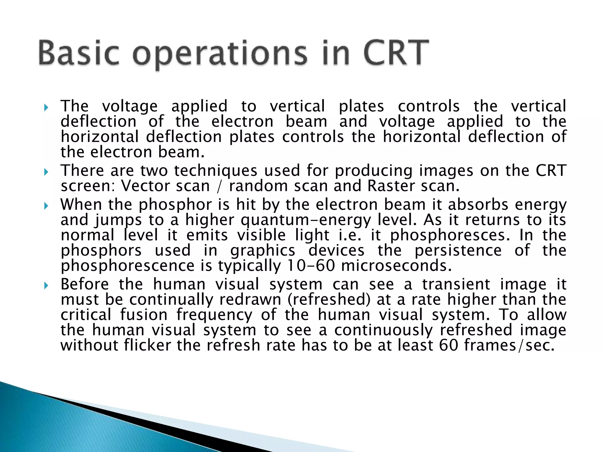


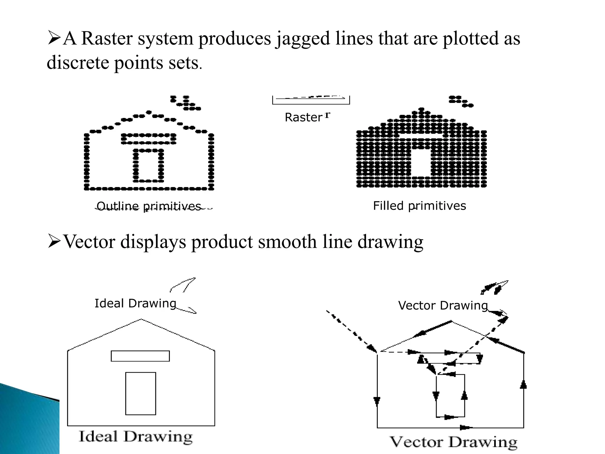


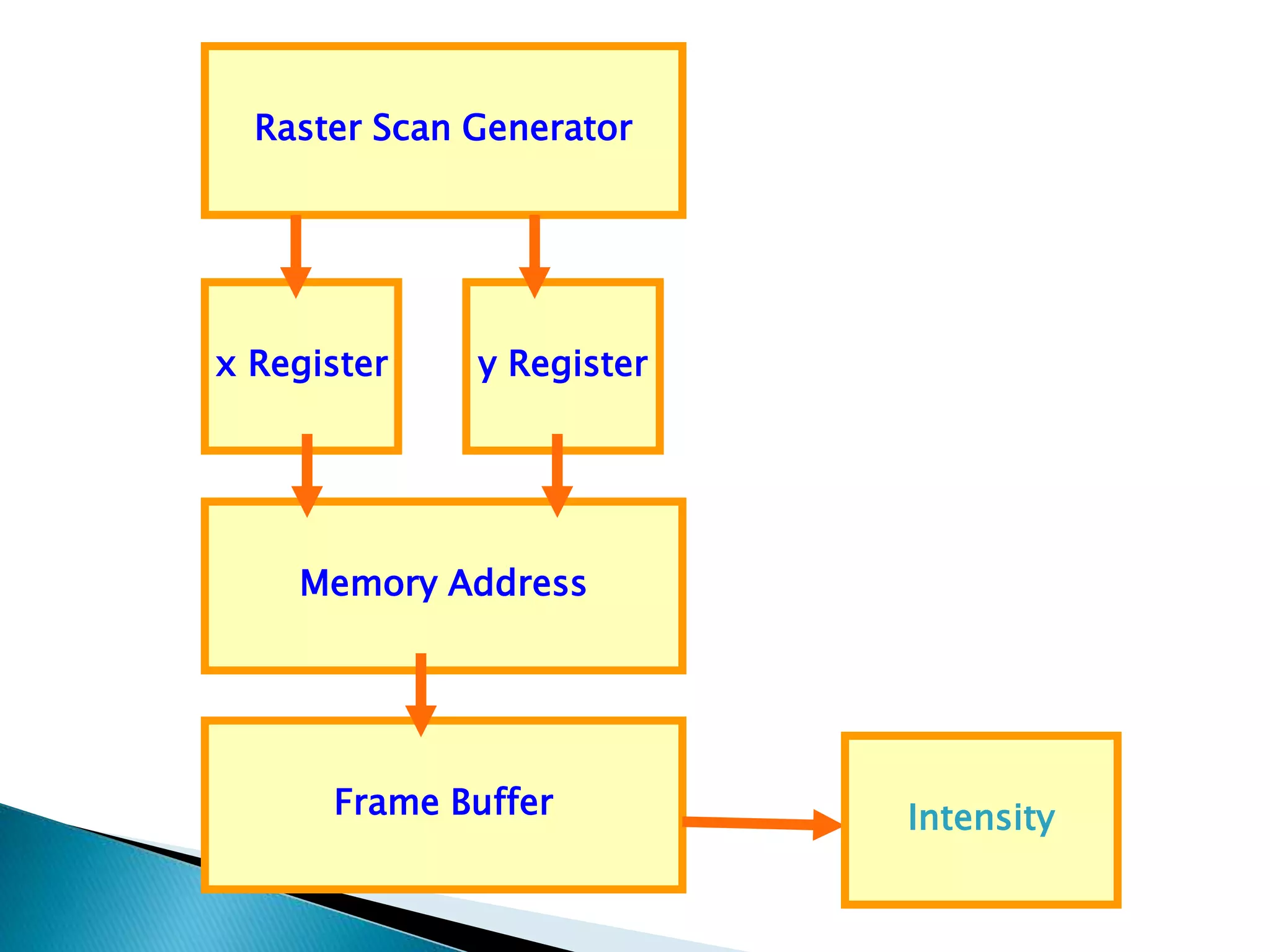

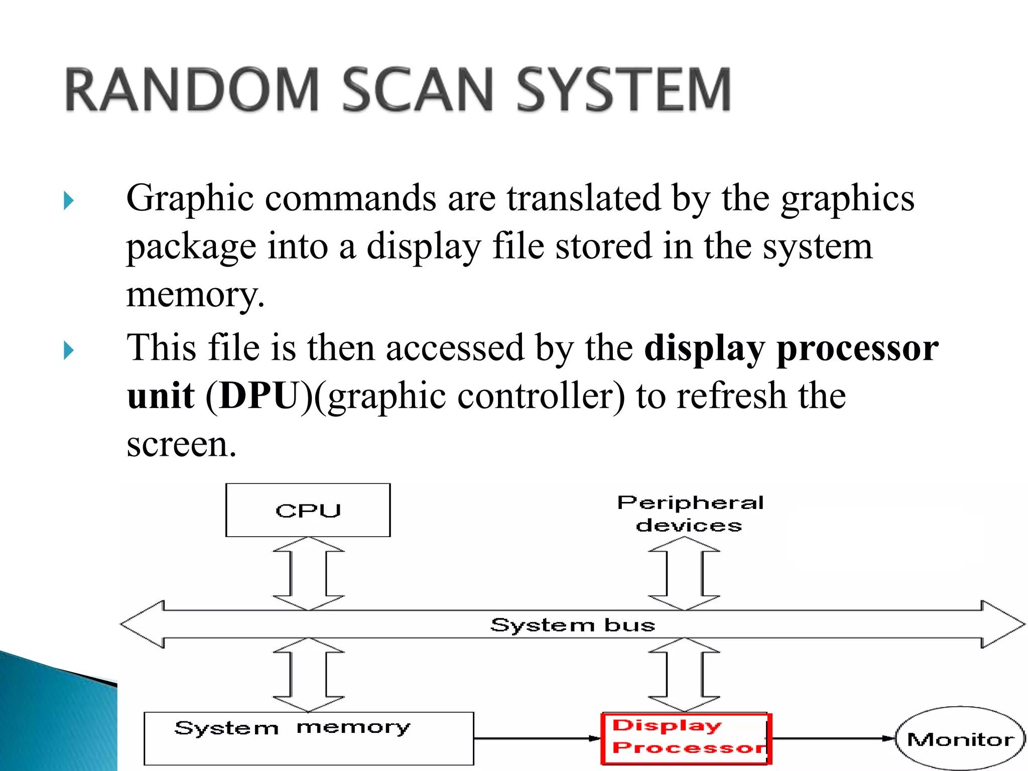
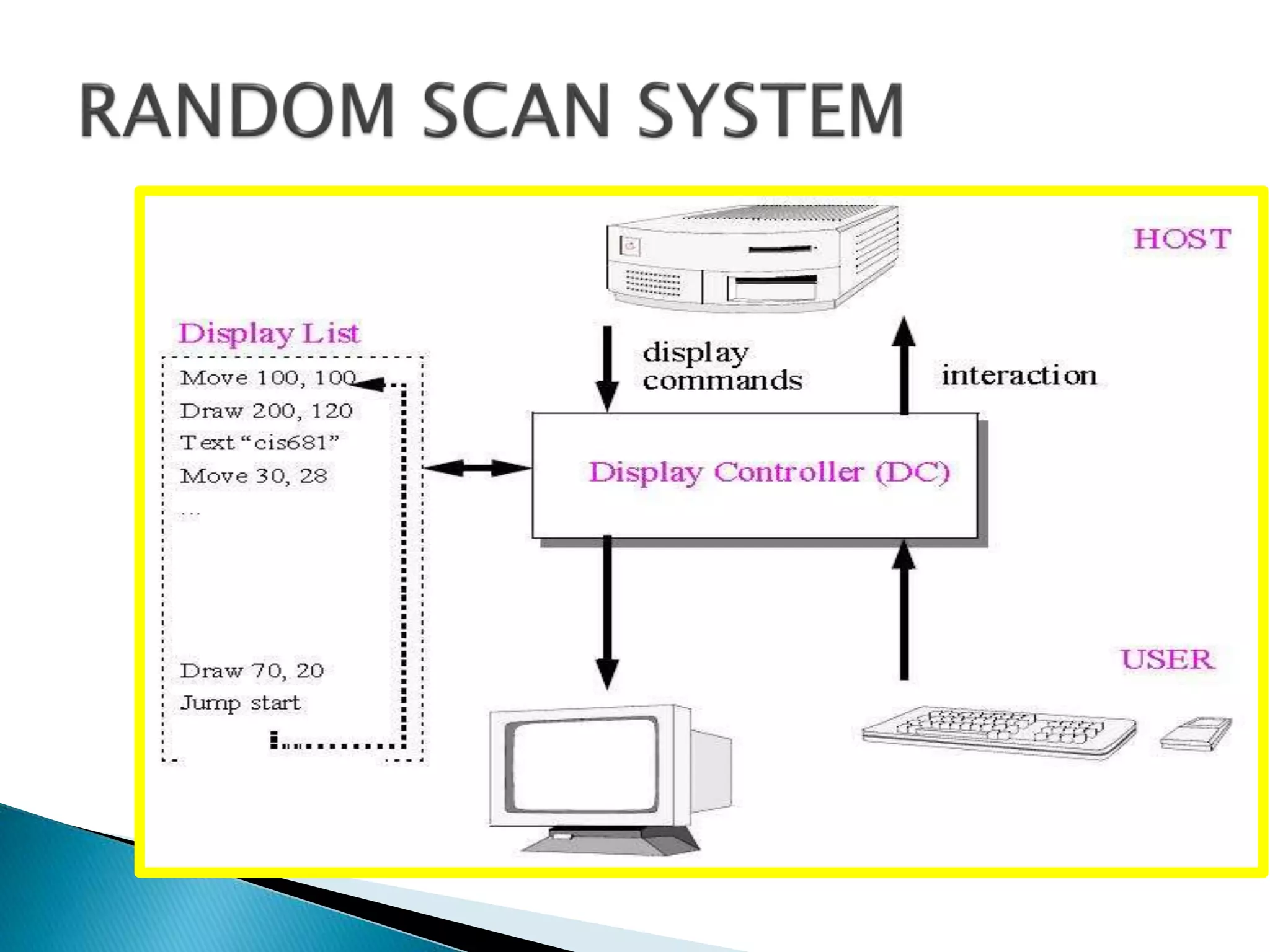
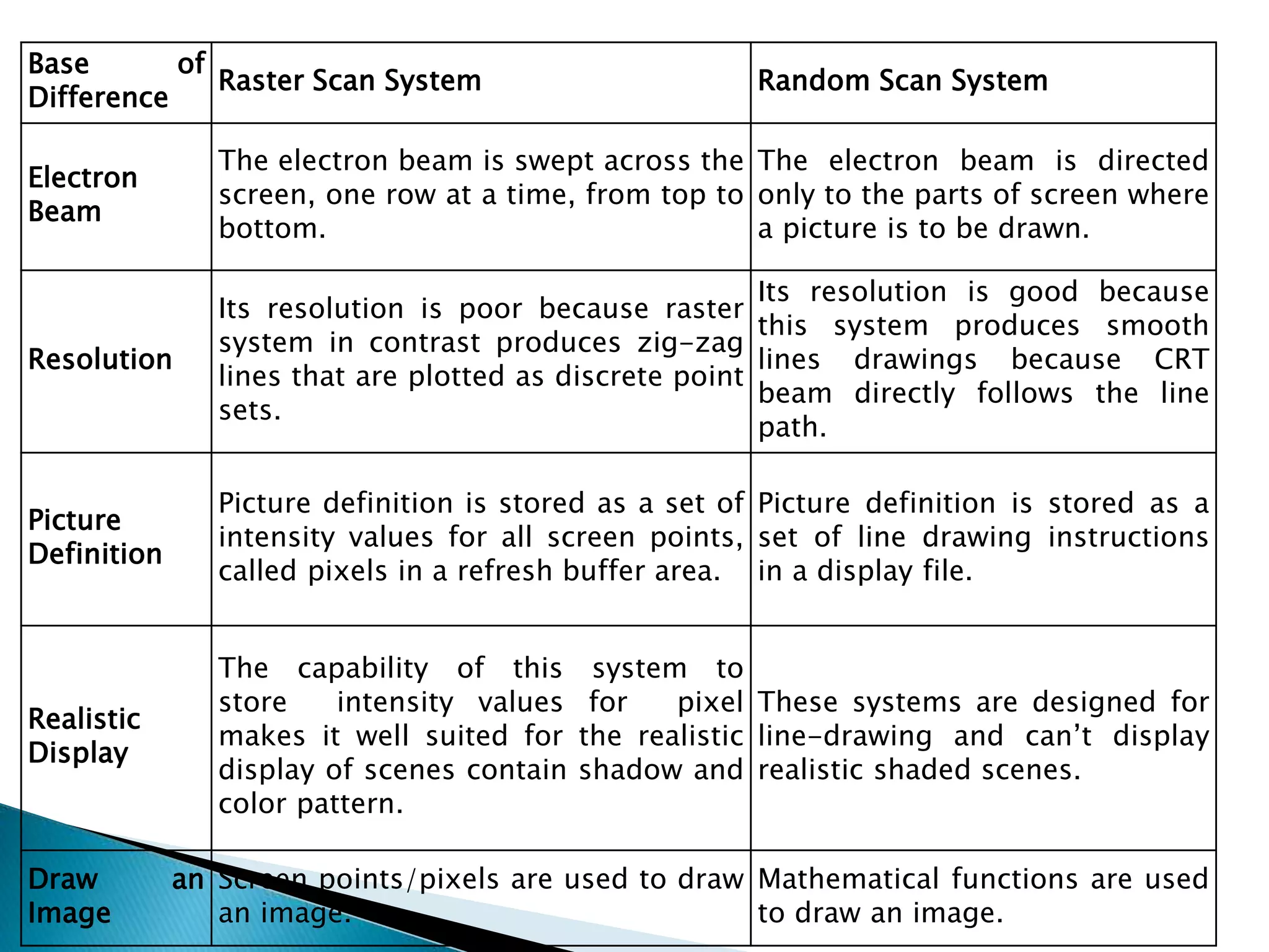

The document explains the functioning of cathode-ray tubes (CRTs) in computer graphics, detailing how electron beams create images on screens through raster and random scan techniques. It discusses the importance of refresh rates for flicker-free images, the generation of raster images as collections of pixels, and the differences between raster and random scan displays in terms of resolution and image quality. Additionally, it covers the role of display processors in managing graphics operations and the storage of image definitions in frame buffers and display files.