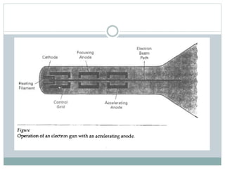
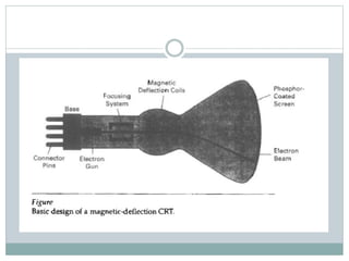
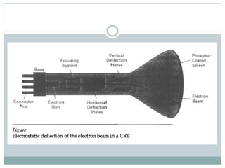
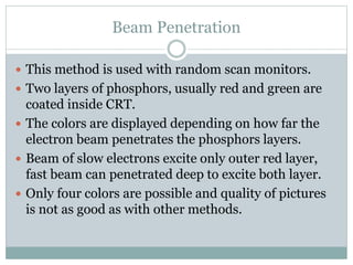
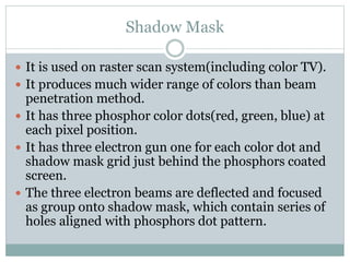
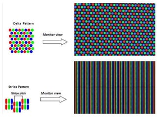
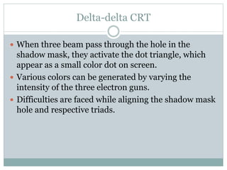
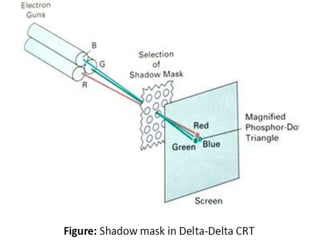
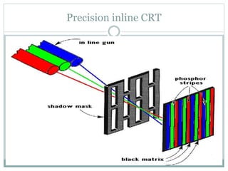
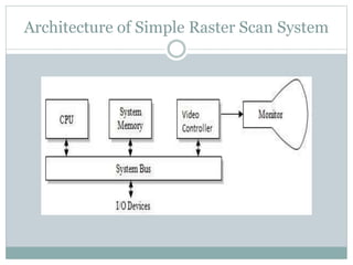
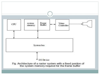
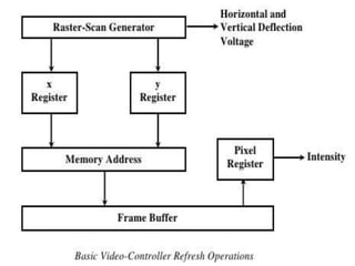
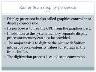
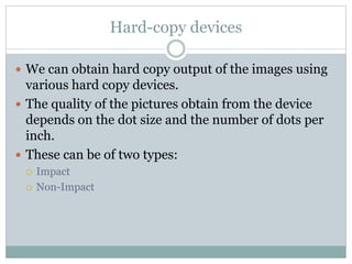
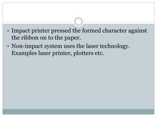
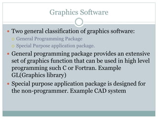
DISPLAY TECHNOLOGIES
RASTER SCAN SYSTEM
RANDOM SCAN SYSTEM
HARD COPY DEVICES
GRAPHICS SOFTWARE
Overview of the Graphics
System
Video Display Devices
 The primary output device in a graphics system is a
video monitor.
 The operation of most video monitor is based on the
standard Cathode Ray Tube(CRT)
Refresh Cathode Ray Tubes
 Electron are “boiled off” the surface of cathode by
heating it with the help of the heating filament.
 The accelerating voltage is generated with the help of
positively charged metal coating on the inside of CRT
envelope or an accelerating anode can be used.
 The intensity of the electron beam is controlled by
setting the negative voltage of the control grid.
 Focusing system is needed to force the electron beam
to converge into small spot as it strikes the
phosphorous.
 Focusing can be implemented with the help of
electric field or the magnetic field.
 As in the case of focusing of the electron, the
deflection of the electron can be controlled by using
either magnetic or the electric field.
 Different kind of Phosphors are available for use in
CRT. Beside color major difference between
phosphors is their persistence.
 Persistence is defined as the time it takes for the
emitted light on the screen to decay one-tenth of its
original intensity.
 A phosphors with low persistence is used in
animation while the other one is useful in displaying
highly complex, static pictures.
 The maximum number of points that can be
displayed on the screen without overlap is referred to
as the resolution.
 High resolution system are referred to as high-
definition system.
 The physical size of the graphical monitor is given as
the length of the screen diagonal.
 Aspect ratio is the ratio of vertical points to
horizontal points required to produce equal length
lines in both direction on the screen.
Raster Scan Display
 The electron beam is swept across the screen one
row at a time top to bottom.
 As the electron beam moves across each row, beam
intensity is turned ON and OFF to create the pattern
of illuminated spots.
 Picture definition is stored in the memory area called
refresh buffer or frame buffer.
 Each screen point is referred to as pixel or
pel(picture element)
 On a black white system with one bit per pixel, the
frame buffer is commonly called bitmap.
 For a system with multiple bits per pixel, the frame
buffer is often referred to as pixmap.
 Refreshing on raster scan display is carried out at the
rate of 60 to 80 frames per second.
 On some rater scan system, each frame is displayed
in two passes using an interlaced refresh procedure.
Interlaced vs Non-Interlaced Scan
 In interlaced scan, each frame is displayed in two
passes. First pass for odd scan lines and second for
the even.
 In non-interlaced scan, electron beam sweep over all
the scan lines.
Question
 Consider a RGB raster system is to be designed using 8
inch by 10 inch screen with a resolution of 100 pixels
per inch in each direction. If we want to store 8 bits per
pixel in the frame buffer, how much storage (in bytes)
do we need for the frame buffer?
Question
 Consider 512 pixels X 512 scan lines image with 24-bit
true color. If 5 minutes video is required to capture,
calculate the total memory required?
Random scan display
 Electron beam is directed only to part of the screen
where a picture is to be drawn.
 It is also referred to as vector display or stroke-
writing or calligraphic displays.
 The components lines of a picture can be drawn and
refreshed in any specified order.
 Refresh rate depends on the number of lines to be
displayed.
 Picture set is stored as the line drawing commands in
memory called refresh display file or display list or
display program or simply refresh buffer.
 It is suited for line drawing application and cannot
display realistic shaded scenes.
 Vector display has higher resolution than raster scan
display.
 Vector display produce smooth line drawing as beam
directly follow the line path.
Color CRT Monitors
 Color pictures can be displayed by using a
combination of phosphors that emit different colored
light.
 By combining these different light, range of colors
can be generated.
 Two basic techniques used are:
 Beam Penetration
 Shadow Mask
Beam Penetration
 This method is used with random scan monitors.
 Two layers of phosphors, usually red and green are
coated inside CRT.
 The colors are displayed depending on how far the
electron beam penetrates the phosphors layers.
 Beam of slow electrons excite only outer red layer,
fast beam can penetrated deep to excite both layer.
 Only four colors are possible and quality of pictures
is not as good as with other methods.
Shadow Mask
 It is used on raster scan system(including color TV).
 It produces much wider range of colors than beam
penetration method.
 It has three phosphor color dots(red, green, blue) at
each pixel position.
 It has three electron gun one for each color dot and
shadow mask grid just behind the phosphors coated
screen.
 The three electron beams are deflected and focused
as group onto shadow mask, which contain series of
holes aligned with phosphors dot pattern.
 There are two primary variations
 Stripe Pattern
 Delta Pattern
Delta-delta CRT
 When three beam pass through the hole in the
shadow mask, they activate the dot triangle, which
appear as a small color dot on screen.
 Various colors can be generated by varying the
intensity of the three electron guns.
 Difficulties are faced while aligning the shadow mask
hole and respective triads.
Precision inline CRT
Direct View Storage Tubes(DVST)
 It store the picture information as a charge
distribution just behind the phosphors coated
screen.
 Two electrons gun are used. Primary gun to store
picture pattern and the second flood gun, maintains
the picture display.
 Because no refreshing is needed, very complex
pictures can be displayed at very high resolution
without any flicker.
 Disadvantage is that they ordinarily do not display
color and selected part of the pictures can not be
displayed.
 To eliminate the picture section, the entire screen
must be erased and modified picture is redrawn.
Flat Panel display
 Flat panel display refers to class of video devices that
have reduced volume, weight and power
requirements compared to CRT.
 They are used in calculators, pocket video games,
laptops, Tv monitors etc.
 We can separate flat panel displays into two
categories:
 Emissive displays
 Non-emissive displays
 Emissive display are the devices that convert the
electrical energy into light. Examples are plasma
panel, LED etc.
 Non-emissive display use optical effects to convert
sunlight or light from some other source into
graphical patterns. Example LCD
Architecture of Simple Raster Scan System
Raster Scan display processor
 Display processor is also called graphics controller or
display coprocessor.
 Its purpose is to free the CPU from the graphics part.
 In addition to the system memory separate display
processor memory can also be provided.
 The major task is to digitize the picture definition
into set of pixel-intensity values for storage in the
frame buffer.
 The digitization process is called scan conversion.
Architecture of Raster Scan Display Processor
Random Scan System
 An application program is input and store in the
system memory along with graphics package.
 Graphics command in application program are
translated by graphics package and stored in the
display file in the system memory.
 This display file is accessed by the processor to
refresh screen.
 Graphics pattern are drawn by directing electron
beam along components line of the picture.
Architecture of Random Scan System
Hard-copy devices
 We can obtain hard copy output of the images using
various hard copy devices.
 The quality of the pictures obtain from the device
depends on the dot size and the number of dots per
inch.
 These can be of two types:
 Impact
 Non-Impact
 Impact printer pressed the formed character against
the ribbon on to the paper.
 Non-impact system uses the laser technology.
Examples laser printer, plotters etc.
Graphics Software
 Two general classification of graphics software:
 General Programming Package
 Special Purpose application package.
 General programming package provides an extensive
set of graphics function that can be used in high level
programming such C or Fortran. Example
GL(Graphics library)
 Special purpose application package is designed for
the non-programmer. Example CAD system

Overview of the graphics system

  • 1.
    DISPLAY TECHNOLOGIES RASTER SCANSYSTEM RANDOM SCAN SYSTEM HARD COPY DEVICES GRAPHICS SOFTWARE Overview of the Graphics System
  • 2.
    Video Display Devices The primary output device in a graphics system is a video monitor.  The operation of most video monitor is based on the standard Cathode Ray Tube(CRT)
  • 3.
    Refresh Cathode RayTubes  Electron are “boiled off” the surface of cathode by heating it with the help of the heating filament.  The accelerating voltage is generated with the help of positively charged metal coating on the inside of CRT envelope or an accelerating anode can be used.  The intensity of the electron beam is controlled by setting the negative voltage of the control grid.  Focusing system is needed to force the electron beam to converge into small spot as it strikes the phosphorous.
  • 4.
     Focusing canbe implemented with the help of electric field or the magnetic field.  As in the case of focusing of the electron, the deflection of the electron can be controlled by using either magnetic or the electric field.
  • 8.
     Different kindof Phosphors are available for use in CRT. Beside color major difference between phosphors is their persistence.  Persistence is defined as the time it takes for the emitted light on the screen to decay one-tenth of its original intensity.  A phosphors with low persistence is used in animation while the other one is useful in displaying highly complex, static pictures.
  • 9.
     The maximumnumber of points that can be displayed on the screen without overlap is referred to as the resolution.  High resolution system are referred to as high- definition system.  The physical size of the graphical monitor is given as the length of the screen diagonal.  Aspect ratio is the ratio of vertical points to horizontal points required to produce equal length lines in both direction on the screen.
  • 10.
    Raster Scan Display The electron beam is swept across the screen one row at a time top to bottom.  As the electron beam moves across each row, beam intensity is turned ON and OFF to create the pattern of illuminated spots.  Picture definition is stored in the memory area called refresh buffer or frame buffer.  Each screen point is referred to as pixel or pel(picture element)
  • 11.
     On ablack white system with one bit per pixel, the frame buffer is commonly called bitmap.  For a system with multiple bits per pixel, the frame buffer is often referred to as pixmap.  Refreshing on raster scan display is carried out at the rate of 60 to 80 frames per second.  On some rater scan system, each frame is displayed in two passes using an interlaced refresh procedure.
  • 14.
    Interlaced vs Non-InterlacedScan  In interlaced scan, each frame is displayed in two passes. First pass for odd scan lines and second for the even.  In non-interlaced scan, electron beam sweep over all the scan lines.
  • 15.
    Question  Consider aRGB raster system is to be designed using 8 inch by 10 inch screen with a resolution of 100 pixels per inch in each direction. If we want to store 8 bits per pixel in the frame buffer, how much storage (in bytes) do we need for the frame buffer?
  • 16.
    Question  Consider 512pixels X 512 scan lines image with 24-bit true color. If 5 minutes video is required to capture, calculate the total memory required?
  • 17.
    Random scan display Electron beam is directed only to part of the screen where a picture is to be drawn.  It is also referred to as vector display or stroke- writing or calligraphic displays.  The components lines of a picture can be drawn and refreshed in any specified order.  Refresh rate depends on the number of lines to be displayed.  Picture set is stored as the line drawing commands in memory called refresh display file or display list or display program or simply refresh buffer.
  • 18.
     It issuited for line drawing application and cannot display realistic shaded scenes.  Vector display has higher resolution than raster scan display.  Vector display produce smooth line drawing as beam directly follow the line path.
  • 20.
    Color CRT Monitors Color pictures can be displayed by using a combination of phosphors that emit different colored light.  By combining these different light, range of colors can be generated.  Two basic techniques used are:  Beam Penetration  Shadow Mask
  • 21.
    Beam Penetration  Thismethod is used with random scan monitors.  Two layers of phosphors, usually red and green are coated inside CRT.  The colors are displayed depending on how far the electron beam penetrates the phosphors layers.  Beam of slow electrons excite only outer red layer, fast beam can penetrated deep to excite both layer.  Only four colors are possible and quality of pictures is not as good as with other methods.
  • 22.
    Shadow Mask  Itis used on raster scan system(including color TV).  It produces much wider range of colors than beam penetration method.  It has three phosphor color dots(red, green, blue) at each pixel position.  It has three electron gun one for each color dot and shadow mask grid just behind the phosphors coated screen.  The three electron beams are deflected and focused as group onto shadow mask, which contain series of holes aligned with phosphors dot pattern.
  • 23.
     There aretwo primary variations  Stripe Pattern  Delta Pattern
  • 25.
    Delta-delta CRT  Whenthree beam pass through the hole in the shadow mask, they activate the dot triangle, which appear as a small color dot on screen.  Various colors can be generated by varying the intensity of the three electron guns.  Difficulties are faced while aligning the shadow mask hole and respective triads.
  • 27.
  • 28.
    Direct View StorageTubes(DVST)  It store the picture information as a charge distribution just behind the phosphors coated screen.  Two electrons gun are used. Primary gun to store picture pattern and the second flood gun, maintains the picture display.  Because no refreshing is needed, very complex pictures can be displayed at very high resolution without any flicker.
  • 29.
     Disadvantage isthat they ordinarily do not display color and selected part of the pictures can not be displayed.  To eliminate the picture section, the entire screen must be erased and modified picture is redrawn.
  • 30.
    Flat Panel display Flat panel display refers to class of video devices that have reduced volume, weight and power requirements compared to CRT.  They are used in calculators, pocket video games, laptops, Tv monitors etc.  We can separate flat panel displays into two categories:  Emissive displays  Non-emissive displays
  • 31.
     Emissive displayare the devices that convert the electrical energy into light. Examples are plasma panel, LED etc.  Non-emissive display use optical effects to convert sunlight or light from some other source into graphical patterns. Example LCD
  • 32.
    Architecture of SimpleRaster Scan System
  • 35.
    Raster Scan displayprocessor  Display processor is also called graphics controller or display coprocessor.  Its purpose is to free the CPU from the graphics part.  In addition to the system memory separate display processor memory can also be provided.  The major task is to digitize the picture definition into set of pixel-intensity values for storage in the frame buffer.  The digitization process is called scan conversion.
  • 36.
    Architecture of RasterScan Display Processor
  • 37.
    Random Scan System An application program is input and store in the system memory along with graphics package.  Graphics command in application program are translated by graphics package and stored in the display file in the system memory.  This display file is accessed by the processor to refresh screen.  Graphics pattern are drawn by directing electron beam along components line of the picture.
  • 38.
  • 40.
    Hard-copy devices  Wecan obtain hard copy output of the images using various hard copy devices.  The quality of the pictures obtain from the device depends on the dot size and the number of dots per inch.  These can be of two types:  Impact  Non-Impact
  • 41.
     Impact printerpressed the formed character against the ribbon on to the paper.  Non-impact system uses the laser technology. Examples laser printer, plotters etc.
  • 42.
    Graphics Software  Twogeneral classification of graphics software:  General Programming Package  Special Purpose application package.  General programming package provides an extensive set of graphics function that can be used in high level programming such C or Fortran. Example GL(Graphics library)  Special purpose application package is designed for the non-programmer. Example CAD system