Downloaded 128 times

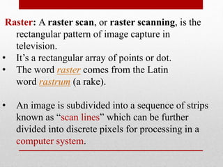
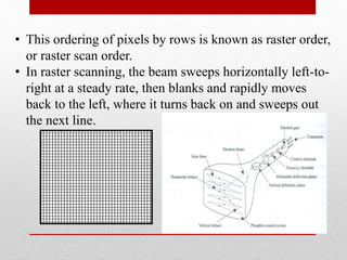
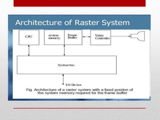

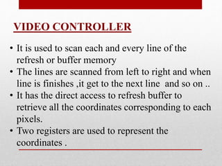
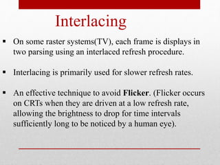
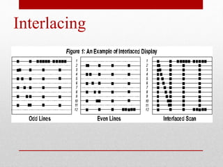

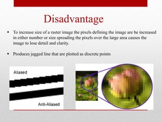


Raster scanning is used in television and involves scanning an image by rows from left to right using a beam. Each point is called a pixel and pixels are stored in a frame buffer along with their color. A video controller scans each line from left to right and then moves to the next line, accessing the frame buffer to retrieve pixel coordinates and colors. Interlacing was used in older TVs and involved scanning alternating lines to reduce flicker at lower refresh rates. The quality of a raster image depends on its resolution and color depth. Raster scanning requires little memory and is less costly than alternatives but images can lose detail when scaled up due to fixed pixel sizes.