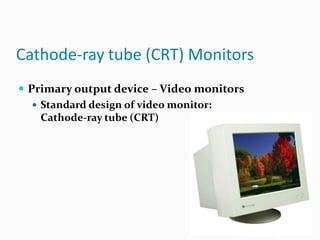
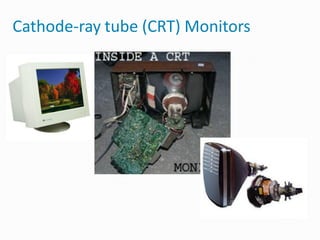
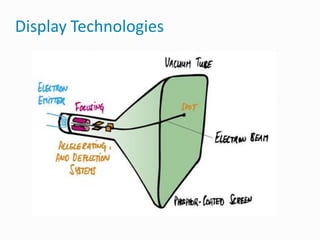
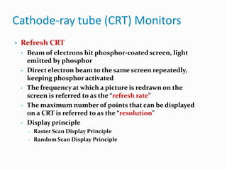
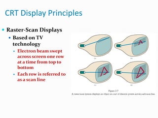
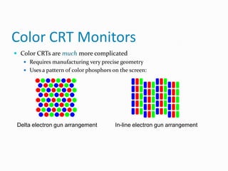
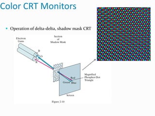
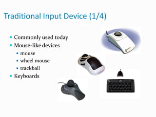
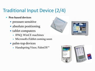
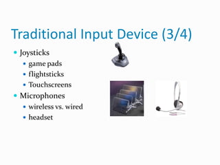
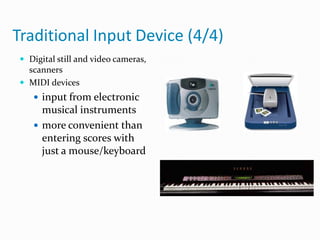
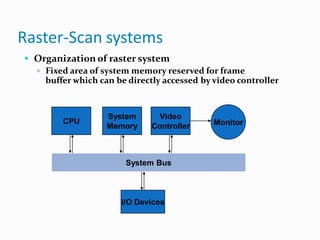
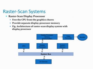
Overview of Graphics Systems
 Video Display Devices
 Input Devices
 Raster-Scan Systems
Video Display Devices
 Cathode-ray tube (CRT) Monitor
 Rater-Scan Displays
 Random-Scan Displays
 Color CRT Monitors
 Flat-Panel Displays
Cathode-ray tube (CRT) Monitors
 Primary output device – Video monitors
 Standard design of video monitor:
Cathode-ray tube (CRT)
Cathode-ray tube (CRT) Monitors
Display Technologies
Cathode-ray tube (CRT) Monitors
 Refresh CRT
 Beam of electrons hit phosphor-coated screen, light
emitted by phosphor
 Direct electron beam to the same screen repeatedly,
keeping phosphor activated
 The frequency at which a picture is redrawn on the
screen is referred to as the “refresh rate”
 The maximum number of points that can be displayed
on a CRT is referred to as the “resolution”
 Display principle
 Raster Scan Display Principle
 Random Scan Display Principle
CRT Display Principles
 Raster-Scan Displays
 Based on TV
technology
 Electron beam swept
across screen one row
at a time from top to
bottom
 Each row is referred to
as a scan line
CRT Display Principles
 Raster-Scan Displays
 Picture elements: screen point referred as “Pixel”
 Picture information stored in refresh (frame)
buffer
CRT Display Principles
 Raster-Scan Displays
 Picture information stored in refresh (frame)
buffer
 The numberof bits per pixel in the frame buffer is called
depth or bit planes
 Buffer with 1 bit per pixel – Bitmap
 Buffer with multiple bits per pixel – Pixmap
 Interlaced refresh procedure
 Beams sweeps across every other scan line
Frame Buffer
 A frame buffer is
characterized by size, x, y,
and pixel depth.
 the resolution of a frame
buffer is the number of
pixels in the display. e.g.
1024x1024 pixels.
 Bit Planes or Bit Depth is
the number of bits
corresponding to each
pixel. This determines the
color resolution of the
buffer.
Refresh Rates and Bandwidth
 Frames per second (FPS)
Interlaced Scanning
 Scan frame 30 times per second
 To reduce flicker, divide frame into two fields—one
consisting of the even scan lines and the other of the
odd scan lines.
 Even and odd fields are scanned out alternately to
produce an interlaced image.
Aspect Ratio
Frame aspect ratio (FAR) = horizontal/vertical size
TV 4:3
HDTV 16:9
Pixel aspect ratio (PAR) = FAR vres/hres
CRT Display Principles
 Random-Scan Display Principles
 Calligraphic Displays also called vector, stroke or line
drawing graphics
 Electron beam directed only to the points of picture
to be displayed.
 Vector displays, electron beams trace out lines to
generate pictures
 Picture stores as a set of line-drawing commands
 Storage referred as display list, refresh display file, vector file
or display program
CRT Display Principles
 Sample of Random-Scan displays principles
Pros and Cons
 Advantages to Raster Displays
 lower cost
 filled regions/shaded images
 Disadvantages to Raster Displays
 a discrete representation, continuous primitives must be
scan-converted (i.e. fill in the appropriate scan lines)
 Aliasing or "jaggies" Arises due to sampling error when
converting from a continuous to a discrete
representation
Color CRT Monitors
 Using a combination of phosphors that emit
different-colored light
 Beam-penetration
 Used in random-scan monitors
 Use red and green phosphors layers
 Color depends on the penetrated length of
electrons
 Shadow mask
 Used in raster-scan systems
 Produce wide range of color with RGB color model
Color CRT Monitors
 Color CRTs are much more complicated
 Requires manufacturing very precise geometry
 Uses a pattern of color phosphors on the screen:
Delta electron gun arrangement In-line electron gun arrangement
Color CRT Monitors
 Operation of delta-delta, shadow mask CRT
Flat-Panel Displays
 A class of video devices that have reduced volume,
weight and power requirement compared with CRT
 Two main categories
 Emissive Displays
 Convert electrical energy to light energy
 e.g. Plasma panels
 Non-emissive Displays
 Use optical effects to convert light from other sources
into graphics patterns
 e.g. LCD monitors
Plasma Panel Display
 Plasma panels (gas-discharge display)
 Contracted by filling the region between two glass
plates
with a mixture of gases
 Refresh buffer used to store picture information
 Firing voltages applied to refresh the pixel
positions
Liquid-crystal Displays
 Liquid-crystal displays (LCD) commonly used in
small systems
 Liquid crystal, compounds have a crystalline
arrangement
of molecules, flow like a liquid
 Passive-matrix LCD
To control light twisting, voltage applied to
intersecting conductors to align the molecules
 Active-matrix LCD
Using thin-film transistor technology, place a
transistor at
each pixel location
Traditional Input Device (1/4)
 Commonly used today
 Mouse-like devices
 mouse
 wheel mouse
 trackball
 Keyboards
Traditional Input Device (2/4)
 Pen-based devices
 pressure sensitive
 absolute positioning
 tablet computers
 IPAQ, WinCE machines
 Microsoft eTablet coming soon
 palm-top devices
 Handspring Visor, PalmOS™
Traditional Input Device (3/4)
 Joysticks
 game pads
 flightsticks
 Touchscreens
 Microphones
 wireless vs. wired
 headset
Traditional Input Device (4/4)
 Digital still and video cameras,
scanners
 MIDI devices
 input from electronic
musical instruments
 more convenient than
entering scores with
just a mouse/keyboard
Raster-Scan systems
 Organization of raster system
 Fixed area of system memory reserved for frame
buffer which can be directly accessed by video controller
CPU
System
Memory
Video
Controller Monitor
System Bus
I/O Devices
Raster-Scan systems
 Video Controller
 Refresh operations
 X, Y register used to indicate pixel position
 Fix Y register and increment X register to generate
scan line
 Double buffering
 Pixel value can be loaded in buffer while
 Providea fast mechanism for real-time animation
generation
Raster-Scan Systems
 Raster-Scan Display Processor
 Free the CPU from the graphics chores
 Provide separate display-processor memory
 Fig. Architecture of raster-scan display system with
display processor
CPU
System
Memory
Display
Processor
System Bus
I/O Devices
Display Processor
memory
(Frame Buffer)
Video
Controller Monitor

Cgmm introduction

  • 2.
    Overview of GraphicsSystems  Video Display Devices  Input Devices  Raster-Scan Systems
  • 3.
    Video Display Devices Cathode-ray tube (CRT) Monitor  Rater-Scan Displays  Random-Scan Displays  Color CRT Monitors  Flat-Panel Displays
  • 4.
    Cathode-ray tube (CRT)Monitors  Primary output device – Video monitors  Standard design of video monitor: Cathode-ray tube (CRT)
  • 5.
  • 6.
  • 7.
    Cathode-ray tube (CRT)Monitors  Refresh CRT  Beam of electrons hit phosphor-coated screen, light emitted by phosphor  Direct electron beam to the same screen repeatedly, keeping phosphor activated  The frequency at which a picture is redrawn on the screen is referred to as the “refresh rate”  The maximum number of points that can be displayed on a CRT is referred to as the “resolution”  Display principle  Raster Scan Display Principle  Random Scan Display Principle
  • 8.
    CRT Display Principles Raster-Scan Displays  Based on TV technology  Electron beam swept across screen one row at a time from top to bottom  Each row is referred to as a scan line
  • 9.
    CRT Display Principles Raster-Scan Displays  Picture elements: screen point referred as “Pixel”  Picture information stored in refresh (frame) buffer
  • 10.
    CRT Display Principles Raster-Scan Displays  Picture information stored in refresh (frame) buffer  The numberof bits per pixel in the frame buffer is called depth or bit planes  Buffer with 1 bit per pixel – Bitmap  Buffer with multiple bits per pixel – Pixmap  Interlaced refresh procedure  Beams sweeps across every other scan line
  • 11.
    Frame Buffer  Aframe buffer is characterized by size, x, y, and pixel depth.  the resolution of a frame buffer is the number of pixels in the display. e.g. 1024x1024 pixels.  Bit Planes or Bit Depth is the number of bits corresponding to each pixel. This determines the color resolution of the buffer.
  • 12.
    Refresh Rates andBandwidth  Frames per second (FPS)
  • 13.
    Interlaced Scanning  Scanframe 30 times per second  To reduce flicker, divide frame into two fields—one consisting of the even scan lines and the other of the odd scan lines.  Even and odd fields are scanned out alternately to produce an interlaced image.
  • 15.
    Aspect Ratio Frame aspectratio (FAR) = horizontal/vertical size TV 4:3 HDTV 16:9 Pixel aspect ratio (PAR) = FAR vres/hres
  • 16.
    CRT Display Principles Random-Scan Display Principles  Calligraphic Displays also called vector, stroke or line drawing graphics  Electron beam directed only to the points of picture to be displayed.  Vector displays, electron beams trace out lines to generate pictures  Picture stores as a set of line-drawing commands  Storage referred as display list, refresh display file, vector file or display program
  • 17.
    CRT Display Principles Sample of Random-Scan displays principles
  • 18.
    Pros and Cons Advantages to Raster Displays  lower cost  filled regions/shaded images  Disadvantages to Raster Displays  a discrete representation, continuous primitives must be scan-converted (i.e. fill in the appropriate scan lines)  Aliasing or "jaggies" Arises due to sampling error when converting from a continuous to a discrete representation
  • 20.
    Color CRT Monitors Using a combination of phosphors that emit different-colored light  Beam-penetration  Used in random-scan monitors  Use red and green phosphors layers  Color depends on the penetrated length of electrons  Shadow mask  Used in raster-scan systems  Produce wide range of color with RGB color model
  • 21.
    Color CRT Monitors Color CRTs are much more complicated  Requires manufacturing very precise geometry  Uses a pattern of color phosphors on the screen: Delta electron gun arrangement In-line electron gun arrangement
  • 22.
    Color CRT Monitors Operation of delta-delta, shadow mask CRT
  • 23.
    Flat-Panel Displays  Aclass of video devices that have reduced volume, weight and power requirement compared with CRT  Two main categories  Emissive Displays  Convert electrical energy to light energy  e.g. Plasma panels  Non-emissive Displays  Use optical effects to convert light from other sources into graphics patterns  e.g. LCD monitors
  • 24.
    Plasma Panel Display Plasma panels (gas-discharge display)  Contracted by filling the region between two glass plates with a mixture of gases  Refresh buffer used to store picture information  Firing voltages applied to refresh the pixel positions
  • 25.
    Liquid-crystal Displays  Liquid-crystaldisplays (LCD) commonly used in small systems  Liquid crystal, compounds have a crystalline arrangement of molecules, flow like a liquid  Passive-matrix LCD To control light twisting, voltage applied to intersecting conductors to align the molecules  Active-matrix LCD Using thin-film transistor technology, place a transistor at each pixel location
  • 26.
    Traditional Input Device(1/4)  Commonly used today  Mouse-like devices  mouse  wheel mouse  trackball  Keyboards
  • 27.
    Traditional Input Device(2/4)  Pen-based devices  pressure sensitive  absolute positioning  tablet computers  IPAQ, WinCE machines  Microsoft eTablet coming soon  palm-top devices  Handspring Visor, PalmOS™
  • 28.
    Traditional Input Device(3/4)  Joysticks  game pads  flightsticks  Touchscreens  Microphones  wireless vs. wired  headset
  • 29.
    Traditional Input Device(4/4)  Digital still and video cameras, scanners  MIDI devices  input from electronic musical instruments  more convenient than entering scores with just a mouse/keyboard
  • 30.
    Raster-Scan systems  Organizationof raster system  Fixed area of system memory reserved for frame buffer which can be directly accessed by video controller CPU System Memory Video Controller Monitor System Bus I/O Devices
  • 31.
    Raster-Scan systems  VideoController  Refresh operations  X, Y register used to indicate pixel position  Fix Y register and increment X register to generate scan line  Double buffering  Pixel value can be loaded in buffer while  Providea fast mechanism for real-time animation generation
  • 32.
    Raster-Scan Systems  Raster-ScanDisplay Processor  Free the CPU from the graphics chores  Provide separate display-processor memory  Fig. Architecture of raster-scan display system with display processor CPU System Memory Display Processor System Bus I/O Devices Display Processor memory (Frame Buffer) Video Controller Monitor