Downloaded 316 times


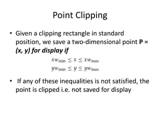
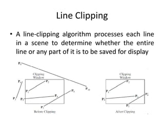

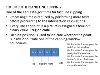
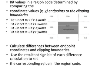

The document discusses 2D viewing and clipping techniques in computer graphics. It describes how clipping is used to select only a portion of an image to display by defining a clipping region. It also discusses 2D viewing transformations which involve operations like translation, rotation and scaling to map coordinates from a world coordinate system to a device coordinate system. It specifically describes the Cohen-Sutherland line clipping algorithm which uses region codes to quickly determine if lines are completely inside, outside or intersect the clipping region to optimize the clipping calculation.