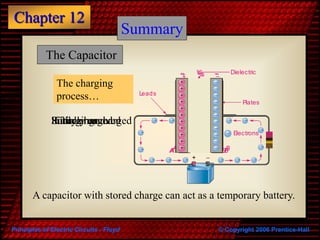
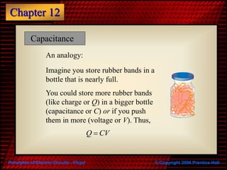
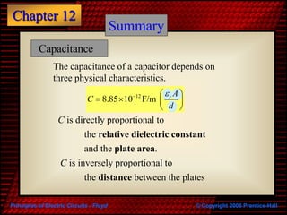
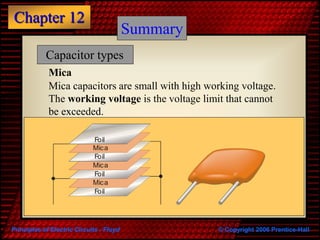
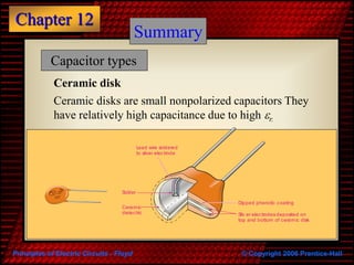
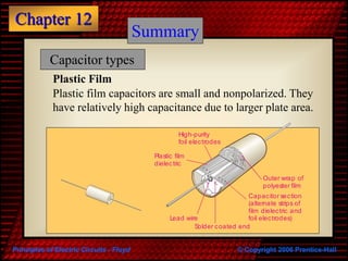
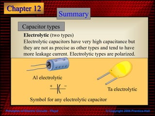
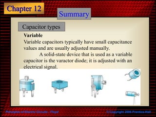
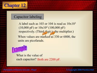
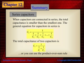
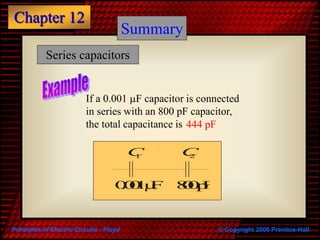
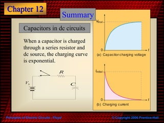
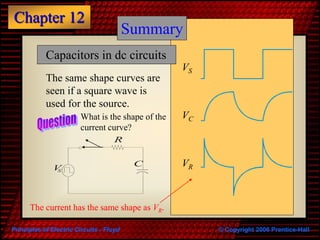
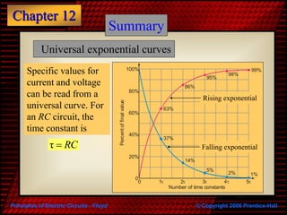
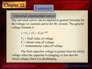
Principles of Electric Circuits - Floyd © Copyright 2006 Prentice-Hall
Chapter 12
High Voltage Capacitor
Principles of Electric Circuits - Floyd © Copyright 2006 Prentice-Hall
Chapter 12
Summary
The Capacitor
Capacitors are one of the fundamental passive
components. In its most basic form, it is composed
of two plates separated by a dielectric.
The ability to store charge is the definition of
capacitance.
DielectricConductors
Principles of Electric Circuits - Floyd © Copyright 2006 Prentice-Hall
Chapter 12
Summary
The Capacitor
Dielectric
Plates
Leads
Electrons
BA




+
+
+
+


+
+
+
+

Initially uncharged
+ 
BA







+
+
+



     



+
+
+
+
Charging
+ 
BA
VS
+
+
+
+
+
+
+
+
+
+
+











Fully charged
BA
VS
+
+
+
+
+
+
+
+
+
+
+
Source removed
The charging
process…
A capacitor with stored charge can act as a temporary battery.
Principles of Electric Circuits - Floyd © Copyright 2006 Prentice-Hall
Chapter 12
Capacitance is the ratio of charge to voltage
Q
C
V

Rearranging, the amount of charge on a
capacitor is determined by the size of the
capacitor (C) and the voltage (V).
Q CV
If a 22 mF capacitor is connected to
a 10 V source, the charge is 220 mC
Capacitance
Principles of Electric Circuits - Floyd © Copyright 2006 Prentice-Hall
Chapter 12
Capacitance
An analogy:
Imagine you store rubber bands in a
bottle that is nearly full.
You could store more rubber bands
(like charge or Q) in a bigger bottle
(capacitance or C) or if you push
them in more (voltage or V). Thus,
Q CV
Principles of Electric Circuits - Floyd © Copyright 2006 Prentice-Hall
Chapter 12
A capacitor stores energy in the form of an electric field
that is established by the opposite charges on the two
plates. The energy of a charged capacitor is given by the
equation
Capacitance
2
2
1
CVW 
where
W = the energy in joules
C = the capacitance in farads
V = the voltage in volts
Principles of Electric Circuits - Floyd © Copyright 2006 Prentice-Hall
Chapter 12
The capacitance of a capacitor depends on
three physical characteristics.
Summary
12
8.85 10 F/m r A
C
d
  
   
 
C is directly proportional to
and the plate area.
the relative dielectric constant
C is inversely proportional to
the distance between the plates
Capacitance
Principles of Electric Circuits - Floyd © Copyright 2006 Prentice-Hall
Chapter 12
12
8.85 10 F/m r A
C
d
  
   
 
Summary
Find the capacitance of a 4.0 cm diameter
sensor immersed in oil if the plates are
separated by 0.25 mm.
The plate area is
The distance between the plates is
Capacitance
 4.0 for oilr 
  3 2
12
3
4.0 1.26 10 m
8.85 10 F/m
0.25 10 m
C



 
   
 
 
3
0.25 10 m

178 pF
 2 2 3 2
π 0.02 m 1.26 10 mA r  
   
Principles of Electric Circuits - Floyd © Copyright 2006 Prentice-Hall
Chapter 12
Summary
Capacitor types
Mica
Mica
Foil
Foil
Mica
Foil
Foil
Mica
Foil
Mica capacitors are small with high working voltage.
The working voltage is the voltage limit that cannot
be exceeded.
Principles of Electric Circuits - Floyd © Copyright 2006 Prentice-Hall
Chapter 12
Summary
Capacitor types
Ceramic disk
Solder
Lead wire soldered
to silver electrode
Ceramic
dielectric
Dipped phenolic coating
Silv er electrodes deposited on
top and bottom of ceramic disk
Ceramic disks are small nonpolarized capacitors They
have relatively high capacitance due to high r.
Principles of Electric Circuits - Floyd © Copyright 2006 Prentice-Hall
Chapter 12
Summary
Capacitor types
Plastic Film
Lead wire
High-purity
foil electrodes
Plastic film
dielectric
Outer wrap of
polyester film
Capacitor section
(alternate strips of
film dielectric and
foil electrodes)
Solder coated end
Plastic film capacitors are small and nonpolarized. They
have relatively high capacitance due to larger plate area.
Principles of Electric Circuits - Floyd © Copyright 2006 Prentice-Hall
Chapter 12
Summary
Capacitor types
Electrolytic (two types)
Symbol for any electrolytic capacitor
Al electrolytic
+
_
Ta electrolytic
Electrolytic capacitors have very high capacitance but
they are not as precise as other types and tend to have
more leakage current. Electrolytic types are polarized.
Principles of Electric Circuits - Floyd © Copyright 2006 Prentice-Hall
Chapter 12
Summary
Capacitor types
Variable
Variable capacitors typically have small capacitance
values and are usually adjusted manually.
A solid-state device that is used as a variable
capacitor is the varactor diode; it is adjusted with an
electrical signal.
Principles of Electric Circuits - Floyd © Copyright 2006 Prentice-Hall
Chapter 12
Capacitor labeling
Capacitors use several labeling methods. Small
capacitors values are frequently stamped on them such
as .001 or .01, which have units of microfarads.
++++
VTTVTT47MF
.022
Electrolytic capacitors have larger
values, so are read as mF. The unit is usually
stamped as mF, but some older ones may be
shown as MF or MMF).
Principles of Electric Circuits - Floyd © Copyright 2006 Prentice-Hall
Chapter 12
A label such as 103 or 104 is read as 10x103
(10,000 pF) or 10x104 (100,000 pF)
respectively. (Third digit is the multiplier.)
Capacitor labeling
When values are marked as 330 or 6800, the
units are picofarads.
What is the value of
each capacitor? Both are 2200 pF.
222 2200
Principles of Electric Circuits - Floyd © Copyright 2006 Prentice-Hall
Chapter 12
Summary
Series capacitors
When capacitors are connected in series, the total
capacitance is smaller than the smallest one. The
general equation for capacitors in series is
T
1 2 3 T
1
1 1 1 1
...
C
C C C C

   
The total capacitance of two capacitors is
T
1 2
1
1 1
C
C C


…or you can use the product-over-sum rule
Principles of Electric Circuits - Floyd © Copyright 2006 Prentice-Hall
Chapter 12
Summary
Series capacitors
If a 0.001 mF capacitor is connected
in series with an 800 pF capacitor,
the total capacitance is 444 pF
0.001µF 800pF
C1 C2
Principles of Electric Circuits - Floyd © Copyright 2006 Prentice-Hall
Chapter 12
Summary
Parallel capacitors
When capacitors are connected in parallel, the total
capacitance is the sum of the individual capacitors.
The general equation for capacitors in parallel is
T 1 2 3 ... nC C C C C   
1800 pF
If a 0.001 mF capacitor is
connected in parallel with
an 800 pF capacitor, the
total capacitance is
0.001µF 800pF
C1 C2
Principles of Electric Circuits - Floyd © Copyright 2006 Prentice-Hall
Chapter 12
Summary
Capacitors in dc circuits
When a capacitor is charged
through a series resistor and
dc source, the charging curve
is exponential.
C
R Iinitial
t0
(b) Charging current
Vfinal
t0
(a) Capacitor charging voltage
Principles of Electric Circuits - Floyd © Copyright 2006 Prentice-Hall
Chapter 12
Summary
Capacitors in dc circuits
When a capacitor is discharged
through a resistor, the
discharge curve is also an
exponential. (Note that the
current is negative.)
t
t
Iinitial
0
(b) Discharging current
Vinitial
0
(a) Capacitor discharging voltage
C
R
Principles of Electric Circuits - Floyd © Copyright 2006 Prentice-Hall
Chapter 12
Summary
Capacitors in dc circuits
The same shape curves are
seen if a square wave is
used for the source.
VS
VC
VRC
R
VS
What is the shape of the
current curve?
The current has the same shape as VR.
Principles of Electric Circuits - Floyd © Copyright 2006 Prentice-Hall
Chapter 12
Summary
Universal exponential curves
Specific values for
current and voltage
can be read from a
universal curve. For
an RC circuit, the
time constant is
τ RC
100%
80%
60%
40%
20%
0
0 1t 2t 3t 4t 5t
99%
98%
95%
86%
63%
37%
14%
5%
2% 1%
Number of time constants
Percentoffinalvalue
Rising exponential
Falling exponential
Principles of Electric Circuits - Floyd © Copyright 2006 Prentice-Hall
Chapter 12
Summary
The universal curves can be applied to general formulas for
the voltage (or current) curves for RC circuits. The general
voltage formula is
v =VF + (Vi  VF)et/RC
VF = final value of voltage
Vi = initial value of voltage
v = instantaneous value of voltage
The final capacitor voltage is greater than the initial
voltage when the capacitor is charging, or less that the
initial voltage when it is discharging.
Universal exponential curves
Principles of Electric Circuits - Floyd © Copyright 2006 Prentice-Hall
Chapter 12
Summary
Capacitive reactance
Capacitive reactance is the opposition to ac
by a capacitor. The equation for capacitive
reactance is
1
2π
CX
fC

The reactance of a 0.047 mF capacitor when a
frequency of 15 kHz is applied is 226 W
Principles of Electric Circuits - Floyd © Copyright 2006 Prentice-Hall
Chapter 12
Summary
Capacitive phase shift
When a sine wave
is applied to a
capacitor, there is a
phase shift between
voltage and current
such that current
always leads the
voltage by 90o.
VC
0
I
0
90
o
Principles of Electric Circuits - Floyd © Copyright 2006 Prentice-Hall
Chapter 12
Summary
Power in a capacitor
Voltage and current are always 90o out of phase.
For this reason, no true power is dissipated by a capacitor,
because stored energy is returned to the circuit.
The rate at which a capacitor stores or returns
energy is called reactive power. The unit for reactive
power is the VAR (volt-ampere reactive).
Energy is stored by the capacitor during a portion of the ac
cycle and returned to the source during another portion of
the cycle.
Principles of Electric Circuits - Floyd © Copyright 2006 Prentice-Hall
Chapter 12
Summary
Switched capacitors
Switched capacitors move charge in a specific time interval
between two points that are different voltages. The
switched capacitors emulate a resistor with a value of
R=1/fC. Switched capacitors are widely used in certain
types of integrated circuits because they can be made very
small, have virtually no drift, and do not dissipate heat.
V1 V2
I1
C
1
0 T/2
2
T
Position 1 Position 1 Position 1
Position 2 Position 2
0 TT/2
+ +
- -
Principles of Electric Circuits - Floyd © Copyright 2006 Prentice-Hall
Chapter 12
Selected Key Terms
Capacitor
Dielectric
Farad
RC time
constant
An electrical device consisting of two conductive
plates separated by an insulating material and
possessing the property of capacitance.
The insulating material between the conductive
plates of a capacitor.
The unit of capacitance.
A fixed time interval set by the R and C values,
that determine the time response of a series RC
circuit. It equals the product of the resistance
and the capacitance.
Principles of Electric Circuits - Floyd © Copyright 2006 Prentice-Hall
Chapter 12
Capacitive
reactance
Instantaneous
power (p)
True power
(Ptrue)
Reactive
power (Pr )
VAR
(volt-ampere
reactive)
The value of power in a circuit at a given
instant of time.
The power that is dissipated in a circuit
usually in the form of heat.
The opposition of a capacitor to sinusoidal
current. The unit is the ohm.
Selected Key Terms
The rate at which energy is alternately stored
and returned to the source by a capacitor. The
unit is the VAR.
The unit of reactive power.

Capacitor high voltage pert. 13

  • 1.
    Principles of ElectricCircuits - Floyd © Copyright 2006 Prentice-Hall Chapter 12 High Voltage Capacitor
  • 2.
    Principles of ElectricCircuits - Floyd © Copyright 2006 Prentice-Hall Chapter 12 Summary The Capacitor Capacitors are one of the fundamental passive components. In its most basic form, it is composed of two plates separated by a dielectric. The ability to store charge is the definition of capacitance. DielectricConductors
  • 3.
    Principles of ElectricCircuits - Floyd © Copyright 2006 Prentice-Hall Chapter 12 Summary The Capacitor Dielectric Plates Leads Electrons BA     + + + +   + + + +  Initially uncharged +  BA        + + +             + + + + Charging +  BA VS + + + + + + + + + + +            Fully charged BA VS + + + + + + + + + + + Source removed The charging process… A capacitor with stored charge can act as a temporary battery.
  • 4.
    Principles of ElectricCircuits - Floyd © Copyright 2006 Prentice-Hall Chapter 12 Capacitance is the ratio of charge to voltage Q C V  Rearranging, the amount of charge on a capacitor is determined by the size of the capacitor (C) and the voltage (V). Q CV If a 22 mF capacitor is connected to a 10 V source, the charge is 220 mC Capacitance
  • 5.
    Principles of ElectricCircuits - Floyd © Copyright 2006 Prentice-Hall Chapter 12 Capacitance An analogy: Imagine you store rubber bands in a bottle that is nearly full. You could store more rubber bands (like charge or Q) in a bigger bottle (capacitance or C) or if you push them in more (voltage or V). Thus, Q CV
  • 6.
    Principles of ElectricCircuits - Floyd © Copyright 2006 Prentice-Hall Chapter 12 A capacitor stores energy in the form of an electric field that is established by the opposite charges on the two plates. The energy of a charged capacitor is given by the equation Capacitance 2 2 1 CVW  where W = the energy in joules C = the capacitance in farads V = the voltage in volts
  • 7.
    Principles of ElectricCircuits - Floyd © Copyright 2006 Prentice-Hall Chapter 12 The capacitance of a capacitor depends on three physical characteristics. Summary 12 8.85 10 F/m r A C d          C is directly proportional to and the plate area. the relative dielectric constant C is inversely proportional to the distance between the plates Capacitance
  • 8.
    Principles of ElectricCircuits - Floyd © Copyright 2006 Prentice-Hall Chapter 12 12 8.85 10 F/m r A C d          Summary Find the capacitance of a 4.0 cm diameter sensor immersed in oil if the plates are separated by 0.25 mm. The plate area is The distance between the plates is Capacitance  4.0 for oilr    3 2 12 3 4.0 1.26 10 m 8.85 10 F/m 0.25 10 m C              3 0.25 10 m  178 pF  2 2 3 2 π 0.02 m 1.26 10 mA r      
  • 9.
    Principles of ElectricCircuits - Floyd © Copyright 2006 Prentice-Hall Chapter 12 Summary Capacitor types Mica Mica Foil Foil Mica Foil Foil Mica Foil Mica capacitors are small with high working voltage. The working voltage is the voltage limit that cannot be exceeded.
  • 10.
    Principles of ElectricCircuits - Floyd © Copyright 2006 Prentice-Hall Chapter 12 Summary Capacitor types Ceramic disk Solder Lead wire soldered to silver electrode Ceramic dielectric Dipped phenolic coating Silv er electrodes deposited on top and bottom of ceramic disk Ceramic disks are small nonpolarized capacitors They have relatively high capacitance due to high r.
  • 11.
    Principles of ElectricCircuits - Floyd © Copyright 2006 Prentice-Hall Chapter 12 Summary Capacitor types Plastic Film Lead wire High-purity foil electrodes Plastic film dielectric Outer wrap of polyester film Capacitor section (alternate strips of film dielectric and foil electrodes) Solder coated end Plastic film capacitors are small and nonpolarized. They have relatively high capacitance due to larger plate area.
  • 12.
    Principles of ElectricCircuits - Floyd © Copyright 2006 Prentice-Hall Chapter 12 Summary Capacitor types Electrolytic (two types) Symbol for any electrolytic capacitor Al electrolytic + _ Ta electrolytic Electrolytic capacitors have very high capacitance but they are not as precise as other types and tend to have more leakage current. Electrolytic types are polarized.
  • 13.
    Principles of ElectricCircuits - Floyd © Copyright 2006 Prentice-Hall Chapter 12 Summary Capacitor types Variable Variable capacitors typically have small capacitance values and are usually adjusted manually. A solid-state device that is used as a variable capacitor is the varactor diode; it is adjusted with an electrical signal.
  • 14.
    Principles of ElectricCircuits - Floyd © Copyright 2006 Prentice-Hall Chapter 12 Capacitor labeling Capacitors use several labeling methods. Small capacitors values are frequently stamped on them such as .001 or .01, which have units of microfarads. ++++ VTTVTT47MF .022 Electrolytic capacitors have larger values, so are read as mF. The unit is usually stamped as mF, but some older ones may be shown as MF or MMF).
  • 15.
    Principles of ElectricCircuits - Floyd © Copyright 2006 Prentice-Hall Chapter 12 A label such as 103 or 104 is read as 10x103 (10,000 pF) or 10x104 (100,000 pF) respectively. (Third digit is the multiplier.) Capacitor labeling When values are marked as 330 or 6800, the units are picofarads. What is the value of each capacitor? Both are 2200 pF. 222 2200
  • 16.
    Principles of ElectricCircuits - Floyd © Copyright 2006 Prentice-Hall Chapter 12 Summary Series capacitors When capacitors are connected in series, the total capacitance is smaller than the smallest one. The general equation for capacitors in series is T 1 2 3 T 1 1 1 1 1 ... C C C C C      The total capacitance of two capacitors is T 1 2 1 1 1 C C C   …or you can use the product-over-sum rule
  • 17.
    Principles of ElectricCircuits - Floyd © Copyright 2006 Prentice-Hall Chapter 12 Summary Series capacitors If a 0.001 mF capacitor is connected in series with an 800 pF capacitor, the total capacitance is 444 pF 0.001µF 800pF C1 C2
  • 18.
    Principles of ElectricCircuits - Floyd © Copyright 2006 Prentice-Hall Chapter 12 Summary Parallel capacitors When capacitors are connected in parallel, the total capacitance is the sum of the individual capacitors. The general equation for capacitors in parallel is T 1 2 3 ... nC C C C C    1800 pF If a 0.001 mF capacitor is connected in parallel with an 800 pF capacitor, the total capacitance is 0.001µF 800pF C1 C2
  • 19.
    Principles of ElectricCircuits - Floyd © Copyright 2006 Prentice-Hall Chapter 12 Summary Capacitors in dc circuits When a capacitor is charged through a series resistor and dc source, the charging curve is exponential. C R Iinitial t0 (b) Charging current Vfinal t0 (a) Capacitor charging voltage
  • 20.
    Principles of ElectricCircuits - Floyd © Copyright 2006 Prentice-Hall Chapter 12 Summary Capacitors in dc circuits When a capacitor is discharged through a resistor, the discharge curve is also an exponential. (Note that the current is negative.) t t Iinitial 0 (b) Discharging current Vinitial 0 (a) Capacitor discharging voltage C R
  • 21.
    Principles of ElectricCircuits - Floyd © Copyright 2006 Prentice-Hall Chapter 12 Summary Capacitors in dc circuits The same shape curves are seen if a square wave is used for the source. VS VC VRC R VS What is the shape of the current curve? The current has the same shape as VR.
  • 22.
    Principles of ElectricCircuits - Floyd © Copyright 2006 Prentice-Hall Chapter 12 Summary Universal exponential curves Specific values for current and voltage can be read from a universal curve. For an RC circuit, the time constant is τ RC 100% 80% 60% 40% 20% 0 0 1t 2t 3t 4t 5t 99% 98% 95% 86% 63% 37% 14% 5% 2% 1% Number of time constants Percentoffinalvalue Rising exponential Falling exponential
  • 23.
    Principles of ElectricCircuits - Floyd © Copyright 2006 Prentice-Hall Chapter 12 Summary The universal curves can be applied to general formulas for the voltage (or current) curves for RC circuits. The general voltage formula is v =VF + (Vi  VF)et/RC VF = final value of voltage Vi = initial value of voltage v = instantaneous value of voltage The final capacitor voltage is greater than the initial voltage when the capacitor is charging, or less that the initial voltage when it is discharging. Universal exponential curves
  • 24.
    Principles of ElectricCircuits - Floyd © Copyright 2006 Prentice-Hall Chapter 12 Summary Capacitive reactance Capacitive reactance is the opposition to ac by a capacitor. The equation for capacitive reactance is 1 2π CX fC  The reactance of a 0.047 mF capacitor when a frequency of 15 kHz is applied is 226 W
  • 25.
    Principles of ElectricCircuits - Floyd © Copyright 2006 Prentice-Hall Chapter 12 Summary Capacitive phase shift When a sine wave is applied to a capacitor, there is a phase shift between voltage and current such that current always leads the voltage by 90o. VC 0 I 0 90 o
  • 26.
    Principles of ElectricCircuits - Floyd © Copyright 2006 Prentice-Hall Chapter 12 Summary Power in a capacitor Voltage and current are always 90o out of phase. For this reason, no true power is dissipated by a capacitor, because stored energy is returned to the circuit. The rate at which a capacitor stores or returns energy is called reactive power. The unit for reactive power is the VAR (volt-ampere reactive). Energy is stored by the capacitor during a portion of the ac cycle and returned to the source during another portion of the cycle.
  • 27.
    Principles of ElectricCircuits - Floyd © Copyright 2006 Prentice-Hall Chapter 12 Summary Switched capacitors Switched capacitors move charge in a specific time interval between two points that are different voltages. The switched capacitors emulate a resistor with a value of R=1/fC. Switched capacitors are widely used in certain types of integrated circuits because they can be made very small, have virtually no drift, and do not dissipate heat. V1 V2 I1 C 1 0 T/2 2 T Position 1 Position 1 Position 1 Position 2 Position 2 0 TT/2 + + - -
  • 28.
    Principles of ElectricCircuits - Floyd © Copyright 2006 Prentice-Hall Chapter 12 Selected Key Terms Capacitor Dielectric Farad RC time constant An electrical device consisting of two conductive plates separated by an insulating material and possessing the property of capacitance. The insulating material between the conductive plates of a capacitor. The unit of capacitance. A fixed time interval set by the R and C values, that determine the time response of a series RC circuit. It equals the product of the resistance and the capacitance.
  • 29.
    Principles of ElectricCircuits - Floyd © Copyright 2006 Prentice-Hall Chapter 12 Capacitive reactance Instantaneous power (p) True power (Ptrue) Reactive power (Pr ) VAR (volt-ampere reactive) The value of power in a circuit at a given instant of time. The power that is dissipated in a circuit usually in the form of heat. The opposition of a capacitor to sinusoidal current. The unit is the ohm. Selected Key Terms The rate at which energy is alternately stored and returned to the source by a capacitor. The unit is the VAR. The unit of reactive power.