1. The document discusses power factor, AC power calculations, and power factor correction for complex loads. It defines real power, reactive power, apparent power, and power factor.
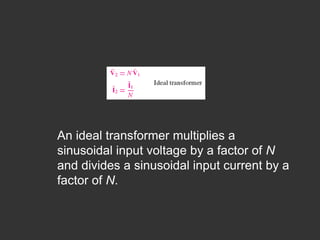
2. Transformers are introduced as devices that couple AC circuits magnetically. An ideal transformer multiplies input voltage by the turn ratio and divides input current by the turn ratio. Impedance is reflected across transformers.
3. Three-phase power systems are discussed, including positive sequence, line voltages, and total constant power for balanced loads in wye and delta configurations.