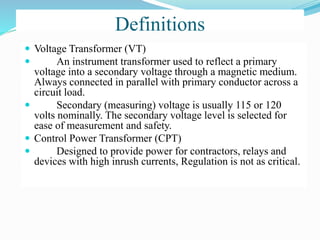
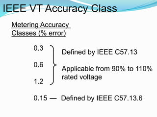
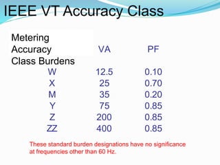
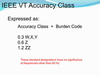
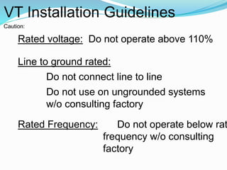
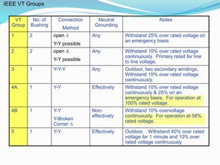
Potential Transformers
Definitions
 Voltage Transformer (VT)
 An instrument transformer used to reflect a primary
voltage into a secondary voltage through a magnetic medium.
Always connected in parallel with primary conductor across a
circuit load.
 Secondary (measuring) voltage is usually 115 or 120
volts nominally. The secondary voltage level is selected for
ease of measurement and safety.
 Control Power Transformer (CPT)
 Designed to provide power for contractors, relays and
devices with high inrush currents, Regulation is not as critical.
POTENTIAL TRANSFORMERS
VP
Vs
Relay
14,400/120 = 120/1
4200/120 = 35/1
2400/120 = 20/1
IEEE VT Accuracy Class
Metering Accuracy
Classes (% error)
0.3
0.6
1.2
0.15
Defined by IEEE C57.13
Applicable from 90% to 110%
rated voltage
Defined by IEEE C57.13.6
IEEE VT Accuracy Class
These standard burden designations have no significance
at frequencies other than 60 Hz.
Burden VA PF
W 12.5 0.10
X 25 0.70
M 35 0.20
Y 75 0.85
Z 200 0.85
ZZ 400 0.85
Metering
Accuracy
Class Burdens
IEEE VT Accuracy Class
Expressed as:
Accuracy Class + Burden Code
0.3 W,X,Y
0.6 Z
1.2 ZZ
These standard designations have no significance
at frequencies other than 60 Hz.
VT Installation Guidelines
Caution:
Rated voltage: Do not operate above 110%
Line to ground rated:
Do not connect line to line
Do not use on ungrounded systems
w/o consulting factory
Rated Frequency: Do not operate below rat
frequency w/o consulting
factory
IEEE VT Groups
VT
Group
No. of
Bushing
Connection
Method
Neutral
Grounding
Notes
1 2 open 
Y-Y possible
Any Withstand 25% over rated voltage on
an emergency basis
2 2 open 
Y-Y possible
Any Withstand 10% over rated voltage
continuously. Primary rated for line
to line voltage.
3 1 Y-Y-Y Any Outdoor, two secondary windings.
Withstand 10% over rated voltage
continuously.
4A 1 Y-Y Effectively Withstand 10% over rated voltage
continuously & 25% on an
emergency basis. For operation at
100% rated voltage.
4B 1 Y-Y
Y-Broken
Corner 
Non-
effectively
Withstand 10% overvoltage
continuously. For operation at 58%
rated voltage.
5 1 Y-Y Effectively Outdoor. Withstand 40% over rated
voltage for 1 minute and 10% over
rated voltage continuously
VT Typical Connections
Open Delta Connection
(2) Double Bushing VTs
Y – Y Connection
(3) Single Bushing VTs

Trafo tegangan

  • 2.
  • 3.
    Definitions  Voltage Transformer(VT)  An instrument transformer used to reflect a primary voltage into a secondary voltage through a magnetic medium. Always connected in parallel with primary conductor across a circuit load.  Secondary (measuring) voltage is usually 115 or 120 volts nominally. The secondary voltage level is selected for ease of measurement and safety.  Control Power Transformer (CPT)  Designed to provide power for contractors, relays and devices with high inrush currents, Regulation is not as critical.
  • 5.
    POTENTIAL TRANSFORMERS VP Vs Relay 14,400/120 =120/1 4200/120 = 35/1 2400/120 = 20/1
  • 6.
    IEEE VT AccuracyClass Metering Accuracy Classes (% error) 0.3 0.6 1.2 0.15 Defined by IEEE C57.13 Applicable from 90% to 110% rated voltage Defined by IEEE C57.13.6
  • 7.
    IEEE VT AccuracyClass These standard burden designations have no significance at frequencies other than 60 Hz. Burden VA PF W 12.5 0.10 X 25 0.70 M 35 0.20 Y 75 0.85 Z 200 0.85 ZZ 400 0.85 Metering Accuracy Class Burdens
  • 8.
    IEEE VT AccuracyClass Expressed as: Accuracy Class + Burden Code 0.3 W,X,Y 0.6 Z 1.2 ZZ These standard designations have no significance at frequencies other than 60 Hz.
  • 10.
    VT Installation Guidelines Caution: Ratedvoltage: Do not operate above 110% Line to ground rated: Do not connect line to line Do not use on ungrounded systems w/o consulting factory Rated Frequency: Do not operate below rat frequency w/o consulting factory
  • 11.
    IEEE VT Groups VT Group No.of Bushing Connection Method Neutral Grounding Notes 1 2 open  Y-Y possible Any Withstand 25% over rated voltage on an emergency basis 2 2 open  Y-Y possible Any Withstand 10% over rated voltage continuously. Primary rated for line to line voltage. 3 1 Y-Y-Y Any Outdoor, two secondary windings. Withstand 10% over rated voltage continuously. 4A 1 Y-Y Effectively Withstand 10% over rated voltage continuously & 25% on an emergency basis. For operation at 100% rated voltage. 4B 1 Y-Y Y-Broken Corner  Non- effectively Withstand 10% overvoltage continuously. For operation at 58% rated voltage. 5 1 Y-Y Effectively Outdoor. Withstand 40% over rated voltage for 1 minute and 10% over rated voltage continuously
  • 12.
    VT Typical Connections OpenDelta Connection (2) Double Bushing VTs Y – Y Connection (3) Single Bushing VTs