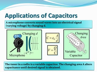
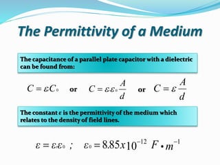
Group 1: BSME IV
Gutierrez, Eduardo Jr. H.
Cabanag, Cleo C.
Capacitance
o Is the ability of a body to store an electrical charge. A material
with a large capacitance holds more electric charge at a given
voltage, than one with low capacitance. Any object that can be
electrically charged exhibits capacitance, however the concept is
particularly important for understanding the operations of the
capacitor, one of the three fundamental electronic components
(along with resistors and inductors).
o The SI unit of capacitance is the farad (symbol: F), named after
the English physicist Michael Faraday. A 1 farad capacitor, when
charged with 1 coulomb of electrical charge, has a potential
difference of 1 volt between its plates
Capacitor
Electronic symbol
o (originally known as a condenser) is a passive two-terminal
electrical component used to temporarily store electrical energy
in an electric field. The forms of practical capacitors vary widely,
but most contain at least two electrical conductors (plates)
separated by a dielectric.
o The conductors can be thin films, foils or sintered beads of
metal or conductive electrolyte, etc. Materials commonly used
as dielectrics include glass, ceramic, plastic film, paper, mica,
and oxide layers.
o Capacitors are widely used as parts of electrical circuits in many
common electrical devices. Unlike a resistor, an ideal capacitor
does not dissipate energy. Instead, a capacitor stores energy in
the form of an electrostatic field between its plates.
Applications of Capacitors
A microphone converts sound waves into an electrical signal
(varying voltage) by changing d.
+
++++++
-
-
-
-
-
- - A
Variable
Capacitor
Changing
Area
0
A
C
d

d
Changing d
Microphone
Q
V
C

The tuner in a radio is a variable capacitor. The changing area A alters
capacitance until desired signal is obtained.
Capacitance in Farads
One farad (F) is the capacitance C of a conductor that
holds one coulomb of charge for each volt of potential.
(C)
; (F)
(V)
Q coulomb
C farad
V volt
 
Example: When 40 μC of charge are placed on a
conductor, the potential is 8 V. What is the capacitance?
C = 5 μF
VV
Q
C
8
C40

Dielectric Materials
o Most capacitors have a dielectric
material between their plates to
provide greater dielectric strength
and less probability for electrical
discharge.
o The separation of dielectric
charge allows more charge to be
placed on the plates—greater
capacitance .
o Materials commonly used as
dielectrics include glass, ceramic,
plastic film, paper, mica, and
oxide layers.
o Smaller plate separation without contact.
o Increases capacitance of a capacitor.
o Higher voltages can be used without
breakdown.
o Often it allows for greater mechanical
strength.
Advantages of Dielectrics
Insertion of Dielectric
+
+
+
+
+
+
Co Vo Eo o
+Q
-Q
++
+Q
-Q
Permittivity increases.
 > o
Capacitance increases.
C > Co
Voltage decreases.
V < Vo
Field decreases.
E < Eo
Insertion of
a dielectric
Same Q
Q = Qo
C V E 
Dielectric Constant, εr
The dielectric constant εr for a material is the ratio of the
capacitance C with this material as compared with the
capacitance Co in a vacuum.
Dielectric constant:
εr= 1 for Air
εr can also be given in terms of voltage V, electric field
intensity E, or permittivity e:
0C
C
r 
0
00


 
E
E
V
V
r
The Permittivity of a Medium
The capacitance of a parallel plate capacitor with a dielectric
can be found from:
The constant ε is the permittivity of the medium which
relates to the density of field lines.
0CC r
d
A
C r 0
d
A
C or or
mFx.; εεεε r
112
1085800




Parallel Plate Capacitance
d
Area
A
+
Q
-Q
0
Q A
C
V d
 
Where:
C=Capacitance (F)
Q=Charge (C)
V=Voltage (V)
A=Area of the plate (m^2)
d=Plate separation (m)
ε0=Permittivity (8.85x10^-12 F/m)
Where:
C=Capacitance (F)
Q=Charge (C)
V=Voltage (V)
A=Area of the plate (m^2)
d=Plate separation (m)
ε0=Permittivity (8.85x10^-12 F/m)
εr=Dielectric constant
 321
0
rrr
nd
A
C 


If capacitor have two or more
dielectric:
Example : Find the capacitance C and the charge Q if connected to
200-V battery. Assume the dielectric constant is εr = 5.0.
2 mmd
A
0.5 m2
  εr 0
  εr 0 5(8.85 x 10⁻¹²F/m)
  44.25 x 10⁻¹² F/m
C = 11.1 nF
Q if connected to V = 200 V?
Q = CV = (11.1 nF)(200 V) Q = 2.22 C
m
m
m
F
x
d
A
C
002.0
)5.0)(1025.44( 212
 
Spherical Capacitor








21
0
11
4
rr
V
Q
C

r1
r1
Where:
C=Capacitance
Q=Charge
V=Voltage
r1=Inside radius
r2=Outside radius r1
ε0=Permittivity (8.85x10^-12 F/m)
If spherical capacitor have two dielectrics:
r2
r3
r1
   23111232
3212104
rrrrrr
rrr
C
rr
rr




εr2
εr1
Cylindrical Capacitor
r1
r2
For a cylindrical geometry like a coaxial
cable, the capacitance is usually stated as a
capacitance per unit length. The charge
resides on the outer surface of the inner
conductor and the inner wall of the outer
conductor. The capacitance expression is







2
1
0
ln
2
r
rL
C r
Where:
C=Capacitance
Q=Charge
V=Voltage
r1=Inside radius
r2=Outside radius r1
L =Length of capacitor
If cylindrical capacitor have two dielectrics:
r2
r3
r1
εr2
εr1

























3
2
1
2
1
2
21
0
lnln
2
r
r
r
r
LC
rr
rr



Example: A cylindrical capacitor of length 8cm is made
of two concentric rings having an inner radius as 3cm
and outer radius as 6cm. Calculate the capacitance of
the capacitor.
Given:
L=8cm=0.08m
r1=3cm=0.03m
r2=6cm=0.06m
1
2
0
ln
2
r
r
LC
r









m
m
m
Fx
mC
03.0
06.0
ln
)1085.8)(1)(2(
)08.0(
12

FxC 12
1042.6 

Capacitors connected in series
Formulas:
nT QQQQ  21
nT VVVV  21
1
1
1
C
Q
V 
2
2
2
C
Q
V 
n
n
n
C
Q
V 
n
T
CCC
C
111
1
21


Capacitors connected in parallel
Formulas:
nT CCCC  21
nT QQQQ  21
nT VVVV  21
111 VCQ  222 VCQ 
nnn VCQ 
Example: C1=10F and C2=5F. Determine the effective
capacitance for C1 and C2 connected in series and in
parallel .
In Series:
21
111
CCCT

5
1
10
1
1

TC
FCT 3.3
In parallel
21 CCCT 
510 TC
FCT 15
Capacitors connected in
series-parallel
C2=4
C4=4C3=4
C1=4
Vt
Sol’n
21
12
11
1
CC
C


4
1
4
1
1
12

C
212 C
43
34
11
1
CC
C


4
1
4
1
1
34

C
234 C
3412 CCCt  22 tC
4tC
Capacitors connected in
series-parallel
C2=4
C4=4C3=4
C1=4
Vt
Sol’n
3113 CCC 
4413 C
813 C
4324 CCC  4424 C
824 C
2413
11
1
CC
Ct


8
1
8
1
1

tC
4tC
Energy storage
The energy (measured in joules) stored in a capacitor is equal to the
work required to push the charges into the capacitor, i.e. to charge
it. Consider a capacitor of capacitance C, holding a charge +q on
one plate and −q on the other. Moving a small element of charge dq
from one plate to the other against the potential difference V = q/C
requires the work dW:
dq
C
q
dW 
where W is the work measured in
joules, q is the charge measured in
coulombs and C is the capacitance,
measured in farads.
The energy stored in a capacitor is found by integrating this
equation. Starting with an uncharged capacitance (q = 0) and
moving charge from one plate to the other until the plates have
charge +Q and −Q requires the work W:
stored
2
2
0 2
1
2
1
2
1
charging WCVQV
C
Q
dq
C
q
W
Q
 
C
Q
W
2
2
1
 QVW
2
1
 2
2
1
CVW 
Example: The capacitor of 1 mF has charged to 100V. What
energy is stored in the capacitor in Joules?
C
Q
W
2
2
1
 QVW
2
1

2
2
1
CVW 
2
)100)(1(
2
1
VFW 
JW 5000
CVQ 
)100)(1( VFQ 
CQ 100
)100)(100(
2
1
VCW 
F
C
W
1
)100(
2
1 2

JW 5000JW 5000

Capacitance and Capacitor

  • 1.
    Group 1: BSMEIV Gutierrez, Eduardo Jr. H. Cabanag, Cleo C.
  • 2.
    Capacitance o Is theability of a body to store an electrical charge. A material with a large capacitance holds more electric charge at a given voltage, than one with low capacitance. Any object that can be electrically charged exhibits capacitance, however the concept is particularly important for understanding the operations of the capacitor, one of the three fundamental electronic components (along with resistors and inductors). o The SI unit of capacitance is the farad (symbol: F), named after the English physicist Michael Faraday. A 1 farad capacitor, when charged with 1 coulomb of electrical charge, has a potential difference of 1 volt between its plates
  • 3.
  • 4.
    o (originally knownas a condenser) is a passive two-terminal electrical component used to temporarily store electrical energy in an electric field. The forms of practical capacitors vary widely, but most contain at least two electrical conductors (plates) separated by a dielectric. o The conductors can be thin films, foils or sintered beads of metal or conductive electrolyte, etc. Materials commonly used as dielectrics include glass, ceramic, plastic film, paper, mica, and oxide layers. o Capacitors are widely used as parts of electrical circuits in many common electrical devices. Unlike a resistor, an ideal capacitor does not dissipate energy. Instead, a capacitor stores energy in the form of an electrostatic field between its plates.
  • 5.
    Applications of Capacitors Amicrophone converts sound waves into an electrical signal (varying voltage) by changing d. + ++++++ - - - - - - - A Variable Capacitor Changing Area 0 A C d  d Changing d Microphone Q V C  The tuner in a radio is a variable capacitor. The changing area A alters capacitance until desired signal is obtained.
  • 6.
    Capacitance in Farads Onefarad (F) is the capacitance C of a conductor that holds one coulomb of charge for each volt of potential. (C) ; (F) (V) Q coulomb C farad V volt   Example: When 40 μC of charge are placed on a conductor, the potential is 8 V. What is the capacitance? C = 5 μF VV Q C 8 C40 
  • 7.
    Dielectric Materials o Mostcapacitors have a dielectric material between their plates to provide greater dielectric strength and less probability for electrical discharge. o The separation of dielectric charge allows more charge to be placed on the plates—greater capacitance . o Materials commonly used as dielectrics include glass, ceramic, plastic film, paper, mica, and oxide layers.
  • 8.
    o Smaller plateseparation without contact. o Increases capacitance of a capacitor. o Higher voltages can be used without breakdown. o Often it allows for greater mechanical strength. Advantages of Dielectrics
  • 9.
    Insertion of Dielectric + + + + + + CoVo Eo o +Q -Q ++ +Q -Q Permittivity increases.  > o Capacitance increases. C > Co Voltage decreases. V < Vo Field decreases. E < Eo Insertion of a dielectric Same Q Q = Qo C V E 
  • 10.
    Dielectric Constant, εr Thedielectric constant εr for a material is the ratio of the capacitance C with this material as compared with the capacitance Co in a vacuum. Dielectric constant: εr= 1 for Air εr can also be given in terms of voltage V, electric field intensity E, or permittivity e: 0C C r  0 00     E E V V r
  • 11.
    The Permittivity ofa Medium The capacitance of a parallel plate capacitor with a dielectric can be found from: The constant ε is the permittivity of the medium which relates to the density of field lines. 0CC r d A C r 0 d A C or or mFx.; εεεε r 112 1085800    
  • 12.
    Parallel Plate Capacitance d Area A + Q -Q 0 QA C V d   Where: C=Capacitance (F) Q=Charge (C) V=Voltage (V) A=Area of the plate (m^2) d=Plate separation (m) ε0=Permittivity (8.85x10^-12 F/m)
  • 13.
    Where: C=Capacitance (F) Q=Charge (C) V=Voltage(V) A=Area of the plate (m^2) d=Plate separation (m) ε0=Permittivity (8.85x10^-12 F/m) εr=Dielectric constant  321 0 rrr nd A C    If capacitor have two or more dielectric:
  • 14.
    Example : Findthe capacitance C and the charge Q if connected to 200-V battery. Assume the dielectric constant is εr = 5.0. 2 mmd A 0.5 m2   εr 0   εr 0 5(8.85 x 10⁻¹²F/m)   44.25 x 10⁻¹² F/m C = 11.1 nF Q if connected to V = 200 V? Q = CV = (11.1 nF)(200 V) Q = 2.22 C m m m F x d A C 002.0 )5.0)(1025.44( 212  
  • 15.
  • 16.
    If spherical capacitorhave two dielectrics: r2 r3 r1    23111232 3212104 rrrrrr rrr C rr rr     εr2 εr1
  • 17.
    Cylindrical Capacitor r1 r2 For acylindrical geometry like a coaxial cable, the capacitance is usually stated as a capacitance per unit length. The charge resides on the outer surface of the inner conductor and the inner wall of the outer conductor. The capacitance expression is        2 1 0 ln 2 r rL C r Where: C=Capacitance Q=Charge V=Voltage r1=Inside radius r2=Outside radius r1 L =Length of capacitor
  • 18.
    If cylindrical capacitorhave two dielectrics: r2 r3 r1 εr2 εr1                          3 2 1 2 1 2 21 0 lnln 2 r r r r LC rr rr   
  • 19.
    Example: A cylindricalcapacitor of length 8cm is made of two concentric rings having an inner radius as 3cm and outer radius as 6cm. Calculate the capacitance of the capacitor. Given: L=8cm=0.08m r1=3cm=0.03m r2=6cm=0.06m 1 2 0 ln 2 r r LC r          m m m Fx mC 03.0 06.0 ln )1085.8)(1)(2( )08.0( 12  FxC 12 1042.6  
  • 20.
    Capacitors connected inseries Formulas: nT QQQQ  21 nT VVVV  21 1 1 1 C Q V  2 2 2 C Q V  n n n C Q V  n T CCC C 111 1 21  
  • 21.
    Capacitors connected inparallel Formulas: nT CCCC  21 nT QQQQ  21 nT VVVV  21 111 VCQ  222 VCQ  nnn VCQ 
  • 22.
    Example: C1=10F andC2=5F. Determine the effective capacitance for C1 and C2 connected in series and in parallel . In Series: 21 111 CCCT  5 1 10 1 1  TC FCT 3.3 In parallel 21 CCCT  510 TC FCT 15
  • 23.
  • 24.
  • 25.
  • 26.
    4324 CCC 4424 C 824 C 2413 11 1 CC Ct   8 1 8 1 1  tC 4tC
  • 27.
    Energy storage The energy(measured in joules) stored in a capacitor is equal to the work required to push the charges into the capacitor, i.e. to charge it. Consider a capacitor of capacitance C, holding a charge +q on one plate and −q on the other. Moving a small element of charge dq from one plate to the other against the potential difference V = q/C requires the work dW: dq C q dW  where W is the work measured in joules, q is the charge measured in coulombs and C is the capacitance, measured in farads.
  • 28.
    The energy storedin a capacitor is found by integrating this equation. Starting with an uncharged capacitance (q = 0) and moving charge from one plate to the other until the plates have charge +Q and −Q requires the work W: stored 2 2 0 2 1 2 1 2 1 charging WCVQV C Q dq C q W Q   C Q W 2 2 1  QVW 2 1  2 2 1 CVW 
  • 29.
    Example: The capacitorof 1 mF has charged to 100V. What energy is stored in the capacitor in Joules? C Q W 2 2 1  QVW 2 1  2 2 1 CVW  2 )100)(1( 2 1 VFW  JW 5000 CVQ  )100)(1( VFQ  CQ 100 )100)(100( 2 1 VCW  F C W 1 )100( 2 1 2  JW 5000JW 5000