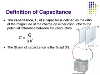
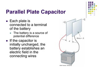
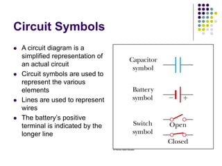
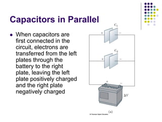
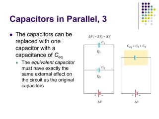
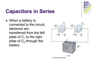
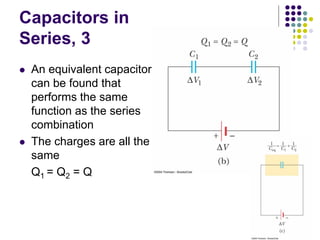
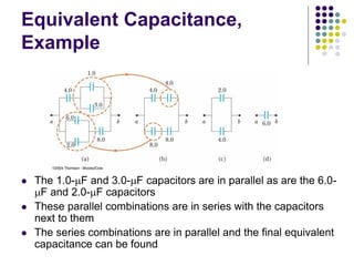
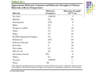
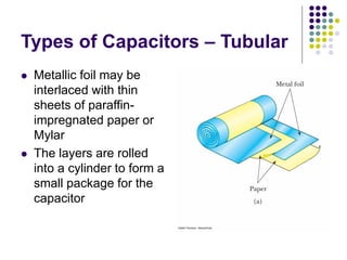
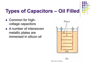
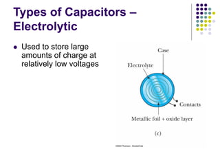
PHY103
General Physics
ELECTRICITY
Electric Potential
Capacitance and dielectrics
Electric Potential
Electrical Potential Energy
 When a test charge is placed in an electric field, it
experiences a force

 The force is conservative
 If the test charge is moved in the field by some
external agent, the work done by the field is the
negative of the work done by the external agent
 is an extremely small displacement vector
o
q

F E
ds
Electric Potential Energy, cont
 The work done by the electric field is
 As this work is done by the field, the potential
energy of the charge-field system is changed
by ΔU =
 For a finite displacement of the charge from A
to B,
 This is the change in potential energy of the
system
B
B A o A
U U U q d
     
 E s
o
d q d
  
F s E s
o
q d
 
E s
Electric Potential
 The potential energy per unit charge, U/qo, is
the electric potential
 The electric potential is
o
U
V
q

 The potential is a scalar quantity
 Since energy is a scalar
 As a charged particle moves in an electric
field, it will experience a change in potential
B
A
o
U
V d
q

    
 E s
Work and Electric Potential
 Assume a charge moves in an electric field
without any change in its kinetic energy
 The work performed on the charge is
W = ΔU = q ΔV
Units
 1 V = 1 J/C
 V is a volt
 It takes one joule of work to move a 1-coulomb charge through a
potential difference of 1 volt
 In addition, 1 N/C = 1 V/m
 This indicates we can interpret the electric field as a measure of
the rate of change with position of the electric potential
Electron-Volts
 Another unit of energy that is commonly used in
atomic and nuclear physics is the electron-volt
 One electron-volt is defined as the energy a
charge-field system gains or loses when a charge of
magnitude e (an electron or a proton) is moved
through a potential difference of 1 volt
 1 eV = 1.60 x 10⁻¹⁹ J
Potential Energy of Multiple
Charges
 Consider two charged
particles
 The potential energy of
the system is
1 2
12
e
q q
U k
r

More About U of Multiple
Charges
 If the two charges are the same sign, U is
positive and work must be done to bring the
charges together
 If the two charges have opposite signs, U is
negative and work is done to keep the
charges apart
U with Multiple Charges, final
 If there are more than
two charges, then find
U for each pair of
charges and add them
 For three charges:
 The result is independent
of the order of the
charges
1 3 2 3
1 2
12 13 23
e
q q q q
q q
U k
r r r
 
  
 
 
Capacitance
and
Dielectrics
Capacitors
 Capacitors are devices that store electric
charge
 Examples of where capacitors are used
include:
 radio receivers
 filters in power supplies
 to eliminate sparking in automobile ignition
systems
 energy-storing devices in electronic flashes
Definition of Capacitance
 The capacitance, C, of a capacitor is defined as the ratio
of the magnitude of the charge on either conductor to the
potential difference between the conductors
 The SI unit of capacitance is the farad (F)
Q
C
V


Makeup of a Capacitor
 A capacitor consists of
two conductors
 These conductors are
called plates
 When the conductor is
charged, the plates carry
charges of equal
magnitude and opposite
directions
 A potential difference
exists between the
plates due to the
charge
More About Capacitance
 Capacitance will always be a positive quantity
 The capacitance of a given capacitor is constant
 The capacitance is a measure of the capacitor’s
ability to store charge
 The farad is a large unit, typically you will see
microfarads (mF) and picofarads (pF)
Parallel Plate Capacitor
 Each plate is
connected to a terminal
of the battery
 The battery is a source of
potential difference
 If the capacitor is
initially uncharged, the
battery establishes an
electric field in the
connecting wires
Parallel Plate Capacitor, cont
 This field applies a force on electrons in the wire just
outside of the plates
 The force causes the electrons to move onto the
negative plate
 This continues until equilibrium is achieved
 The plate, the wire and the terminal are all at the same
potential
 At this point, there is no field present in the wire and
the movement of the electrons ceases
Parallel Plate Capacitor, final
 The plate is now negatively charged
 A similar process occurs at the other plate,
electrons moving away from the plate and
leaving it positively charged
 In its final configuration, the potential
difference across the capacitor plates is the
same as that between the terminals of the
battery
Circuit Symbols
 A circuit diagram is a
simplified representation of
an actual circuit
 Circuit symbols are used to
represent the various
elements
 Lines are used to represent
wires
 The battery’s positive
terminal is indicated by the
longer line
Capacitors in Parallel
 When capacitors are
first connected in the
circuit, electrons are
transferred from the left
plates through the
battery to the right
plate, leaving the left
plate positively charged
and the right plate
negatively charged
Capacitors in Parallel, 2
 The flow of charges ceases when the voltage across
the capacitors equals that of the battery
 The potential difference across the capacitors is the
same
 And each is equal to the voltage of the battery
 V1 = V2 = V
 V is the battery terminal voltage
 The capacitors reach their maximum charge when
the flow of charge ceases
 The total charge is equal to the sum of the charges
on the capacitors
 Qtotal = Q1 + Q2
Capacitors in Parallel, 3
 The capacitors can be
replaced with one
capacitor with a
capacitance of Ceq
 The equivalent capacitor
must have exactly the
same external effect on
the circuit as the original
capacitors
Capacitors in Parallel, final
 Ceq = C1 + C2 + C3 + …
 The equivalent capacitance of a parallel
combination of capacitors is greater than any
of the individual capacitors
Capacitors in Series
 When a battery is
connected to the circuit,
electrons are
transferred from the left
plate of C1 to the right
plate of C2 through the
battery
Capacitors in Series, 2
 As this negative charge accumulates on the
right plate of C2, an equivalent amount of
negative charge is removed from the left
plate of C2, leaving it with an excess positive
charge
 All of the right plates gain charges of –Q and
all the left plates have charges of +Q
Capacitors in
Series, 3
 An equivalent capacitor
can be found that
performs the same
function as the series
combination
 The charges are all the
same
Q1 = Q2 = Q
Capacitors in Series, final
 The potential differences add up to the battery
voltage
ΔVtot = V1 + V2 + …
 The equivalent capacitance is
 The equivalent capacitance of a series combination
is always less than any individual capacitor in the
combination
1 2 3
1 1 1 1
eq
C C C C
   
Equivalent Capacitance,
Example
 The 1.0-mF and 3.0-mF capacitors are in parallel as are the 6.0-
mF and 2.0-mF capacitors
 These parallel combinations are in series with the capacitors
next to them
 The series combinations are in parallel and the final equivalent
capacitance can be found
Capacitors with Dielectrics
 A dielectric is a nonconducting material that,
when placed between the plates of a capacitor,
increases the capacitance
 Dielectrics include rubber, glass, and waxed paper
 With a dielectric, the capacitance becomes
C = κCo
 The capacitance increases by the factor κ when the
dielectric completely fills the region between the plates
 κ is the dielectric constant of the material
Dielectrics, cont
 For a parallel-plate capacitor, C = κεo(A/d)
 In theory, d could be made very small to create a
very large capacitance
 In practice, there is a limit to d
 d is limited by the electric discharge that could occur
though the dielectric medium separating the plates
 For a given d, the maximum voltage that can be
applied to a capacitor without causing a discharge
depends on the dielectric strength of the material
Dielectrics, final
 Dielectrics provide the following advantages:
 Increase in capacitance
 Increase the maximum operating voltage
 Possible mechanical support between the plates
 This allows the plates to be close together without
touching
 This decreases d and increases C
Types of Capacitors – Tubular
 Metallic foil may be
interlaced with thin
sheets of paraffin-
impregnated paper or
Mylar
 The layers are rolled
into a cylinder to form a
small package for the
capacitor
Types of Capacitors – Oil Filled
 Common for high-
voltage capacitors
 A number of interwoven
metallic plates are
immersed in silicon oil
Types of Capacitors –
Electrolytic
 Used to store large
amounts of charge at
relatively low voltages
Types of Capacitors – Variable
 Variable capacitors consist
of two interwoven sets of
metallic plates
 One plate is fixed and the
other is movable
 These capacitors generally
vary between 10 and 500
pF
 Used in radio tuning circuits

General Physics- Electricity

  • 1.
  • 6.
  • 7.
    Electrical Potential Energy When a test charge is placed in an electric field, it experiences a force   The force is conservative  If the test charge is moved in the field by some external agent, the work done by the field is the negative of the work done by the external agent  is an extremely small displacement vector o q  F E ds
  • 8.
    Electric Potential Energy,cont  The work done by the electric field is  As this work is done by the field, the potential energy of the charge-field system is changed by ΔU =  For a finite displacement of the charge from A to B,  This is the change in potential energy of the system B B A o A U U U q d        E s o d q d    F s E s o q d   E s
  • 9.
    Electric Potential  Thepotential energy per unit charge, U/qo, is the electric potential  The electric potential is o U V q   The potential is a scalar quantity  Since energy is a scalar  As a charged particle moves in an electric field, it will experience a change in potential B A o U V d q        E s
  • 10.
    Work and ElectricPotential  Assume a charge moves in an electric field without any change in its kinetic energy  The work performed on the charge is W = ΔU = q ΔV Units  1 V = 1 J/C  V is a volt  It takes one joule of work to move a 1-coulomb charge through a potential difference of 1 volt  In addition, 1 N/C = 1 V/m  This indicates we can interpret the electric field as a measure of the rate of change with position of the electric potential
  • 11.
    Electron-Volts  Another unitof energy that is commonly used in atomic and nuclear physics is the electron-volt  One electron-volt is defined as the energy a charge-field system gains or loses when a charge of magnitude e (an electron or a proton) is moved through a potential difference of 1 volt  1 eV = 1.60 x 10⁻¹⁹ J
  • 12.
    Potential Energy ofMultiple Charges  Consider two charged particles  The potential energy of the system is 1 2 12 e q q U k r 
  • 13.
    More About Uof Multiple Charges  If the two charges are the same sign, U is positive and work must be done to bring the charges together  If the two charges have opposite signs, U is negative and work is done to keep the charges apart
  • 14.
    U with MultipleCharges, final  If there are more than two charges, then find U for each pair of charges and add them  For three charges:  The result is independent of the order of the charges 1 3 2 3 1 2 12 13 23 e q q q q q q U k r r r         
  • 15.
  • 16.
    Capacitors  Capacitors aredevices that store electric charge  Examples of where capacitors are used include:  radio receivers  filters in power supplies  to eliminate sparking in automobile ignition systems  energy-storing devices in electronic flashes
  • 17.
    Definition of Capacitance The capacitance, C, of a capacitor is defined as the ratio of the magnitude of the charge on either conductor to the potential difference between the conductors  The SI unit of capacitance is the farad (F) Q C V  
  • 18.
    Makeup of aCapacitor  A capacitor consists of two conductors  These conductors are called plates  When the conductor is charged, the plates carry charges of equal magnitude and opposite directions  A potential difference exists between the plates due to the charge
  • 19.
    More About Capacitance Capacitance will always be a positive quantity  The capacitance of a given capacitor is constant  The capacitance is a measure of the capacitor’s ability to store charge  The farad is a large unit, typically you will see microfarads (mF) and picofarads (pF)
  • 20.
    Parallel Plate Capacitor Each plate is connected to a terminal of the battery  The battery is a source of potential difference  If the capacitor is initially uncharged, the battery establishes an electric field in the connecting wires
  • 21.
    Parallel Plate Capacitor,cont  This field applies a force on electrons in the wire just outside of the plates  The force causes the electrons to move onto the negative plate  This continues until equilibrium is achieved  The plate, the wire and the terminal are all at the same potential  At this point, there is no field present in the wire and the movement of the electrons ceases
  • 22.
    Parallel Plate Capacitor,final  The plate is now negatively charged  A similar process occurs at the other plate, electrons moving away from the plate and leaving it positively charged  In its final configuration, the potential difference across the capacitor plates is the same as that between the terminals of the battery
  • 23.
    Circuit Symbols  Acircuit diagram is a simplified representation of an actual circuit  Circuit symbols are used to represent the various elements  Lines are used to represent wires  The battery’s positive terminal is indicated by the longer line
  • 24.
    Capacitors in Parallel When capacitors are first connected in the circuit, electrons are transferred from the left plates through the battery to the right plate, leaving the left plate positively charged and the right plate negatively charged
  • 25.
    Capacitors in Parallel,2  The flow of charges ceases when the voltage across the capacitors equals that of the battery  The potential difference across the capacitors is the same  And each is equal to the voltage of the battery  V1 = V2 = V  V is the battery terminal voltage  The capacitors reach their maximum charge when the flow of charge ceases  The total charge is equal to the sum of the charges on the capacitors  Qtotal = Q1 + Q2
  • 26.
    Capacitors in Parallel,3  The capacitors can be replaced with one capacitor with a capacitance of Ceq  The equivalent capacitor must have exactly the same external effect on the circuit as the original capacitors
  • 27.
    Capacitors in Parallel,final  Ceq = C1 + C2 + C3 + …  The equivalent capacitance of a parallel combination of capacitors is greater than any of the individual capacitors
  • 28.
    Capacitors in Series When a battery is connected to the circuit, electrons are transferred from the left plate of C1 to the right plate of C2 through the battery
  • 29.
    Capacitors in Series,2  As this negative charge accumulates on the right plate of C2, an equivalent amount of negative charge is removed from the left plate of C2, leaving it with an excess positive charge  All of the right plates gain charges of –Q and all the left plates have charges of +Q
  • 30.
    Capacitors in Series, 3 An equivalent capacitor can be found that performs the same function as the series combination  The charges are all the same Q1 = Q2 = Q
  • 31.
    Capacitors in Series,final  The potential differences add up to the battery voltage ΔVtot = V1 + V2 + …  The equivalent capacitance is  The equivalent capacitance of a series combination is always less than any individual capacitor in the combination 1 2 3 1 1 1 1 eq C C C C    
  • 32.
    Equivalent Capacitance, Example  The1.0-mF and 3.0-mF capacitors are in parallel as are the 6.0- mF and 2.0-mF capacitors  These parallel combinations are in series with the capacitors next to them  The series combinations are in parallel and the final equivalent capacitance can be found
  • 33.
    Capacitors with Dielectrics A dielectric is a nonconducting material that, when placed between the plates of a capacitor, increases the capacitance  Dielectrics include rubber, glass, and waxed paper  With a dielectric, the capacitance becomes C = κCo  The capacitance increases by the factor κ when the dielectric completely fills the region between the plates  κ is the dielectric constant of the material
  • 34.
    Dielectrics, cont  Fora parallel-plate capacitor, C = κεo(A/d)  In theory, d could be made very small to create a very large capacitance  In practice, there is a limit to d  d is limited by the electric discharge that could occur though the dielectric medium separating the plates  For a given d, the maximum voltage that can be applied to a capacitor without causing a discharge depends on the dielectric strength of the material
  • 35.
    Dielectrics, final  Dielectricsprovide the following advantages:  Increase in capacitance  Increase the maximum operating voltage  Possible mechanical support between the plates  This allows the plates to be close together without touching  This decreases d and increases C
  • 37.
    Types of Capacitors– Tubular  Metallic foil may be interlaced with thin sheets of paraffin- impregnated paper or Mylar  The layers are rolled into a cylinder to form a small package for the capacitor
  • 38.
    Types of Capacitors– Oil Filled  Common for high- voltage capacitors  A number of interwoven metallic plates are immersed in silicon oil
  • 39.
    Types of Capacitors– Electrolytic  Used to store large amounts of charge at relatively low voltages
  • 40.
    Types of Capacitors– Variable  Variable capacitors consist of two interwoven sets of metallic plates  One plate is fixed and the other is movable  These capacitors generally vary between 10 and 500 pF  Used in radio tuning circuits