GUESS WHAT
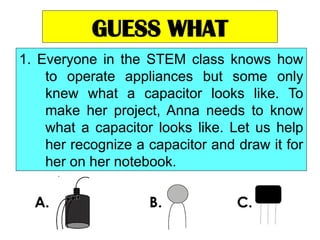
1. Everyonein the STEM class knows how
to operate appliances but some only
knew what a capacitor looks like. To
make her project, Anna needs to know
what a capacitor looks like. Let us help
her recognize a capacitor and draw it for
her on her notebook.
5.
GUESS WHAT
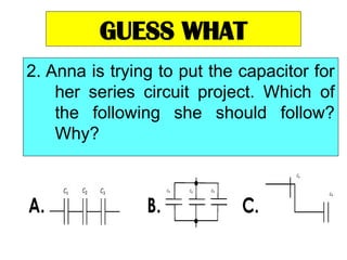
2. Annais trying to put the capacitor for
her series circuit project. Which of
the following she should follow?
Why?
6.
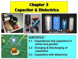
Chapter 3
Capacitor &Dielectrics
SUBTOPICS :
2.1 Capacitance and capacitors in
series and parallel
2.2 Charging & Discharging of
capacitors
2.3 Capacitors with dielectrics
7.
3.0 Introduction
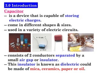
Capacitor
-- isa device that is capable of storing
electric charges.
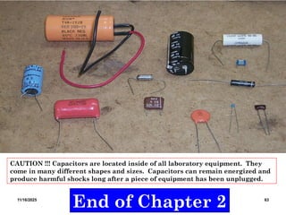
-- come in different shapes & sizes.
-- used in a variety of electric circuits.
-- consists of 2 conductors separated by a
small air gap or insulator.
-- This insulator is known as dielectric could
be made of mica, ceramics, paper or oil.
8.
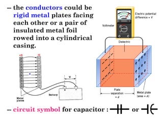
-- the conductorscould be
rigid metal plates facing
each other or a pair of
insulated metal foil
rowed into a cylindrical
casing.
-- circuit symbol for capacitor : or
9.
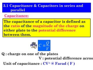
The capacitance ofa capacitor is defined as
the ratio of the magnitude of the charge on
either plate to the potential difference
between them.
V
Q
C
Q : charge on one of the plates
V : potential difference across
Unit of capacitance : CV-1
@ Farad ( F )
3.1 Capacitance & Capacitors in series and
parallel
Capacitance:
10.
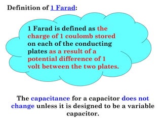
Definition of 1Farad:
1 Farad is defined as the
charge of 1 coulomb stored
on each of the conducting
plates as a result of a
potential difference of 1
volt between the two plates.
The capacitance for a capacitor does not
change unless it is designed to be a variable
capacitor.
11.
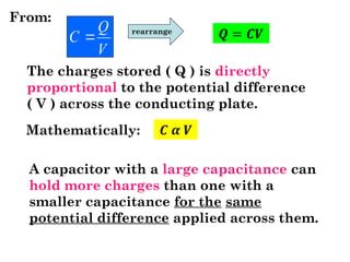
V
Q
C
From:
The chargesstored ( Q ) is directly
proportional to the potential difference
( V ) across the conducting plate.
rearrange
Mathematically:
A capacitor with a large capacitance can
hold more charges than one with a
smaller capacitance for the same
potential difference applied across them.
12.
Capacitors in series& parallel
Capacitors in series
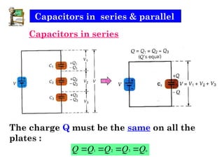
The charge Q must be the same on all the
plates :
n
Q
Q
Q
Q
Q
3
2
1
13.
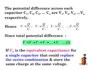
The potential differenceacross each
capacitor C1, C2, C3, … Cn are V1, V2, V3, …Vn
respectively.
Hence
1
1
C
Q
V
2
2
;
C
Q
V
3
3
;
C
Q
V
n
n
C
Q
V
;
Since total potential difference :
)
1
(
3
2
1
n
V
V
V
V
V
If CE is the equivalent capacitance for
a single capacitor that could replace
the series combination & store the
same charge at the same voltage.
14.
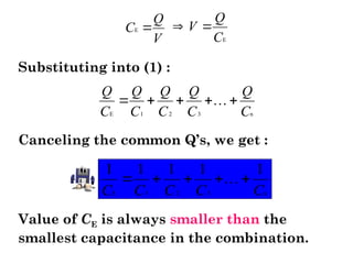
Canceling the commonQ’s, we get :
E 1 2 3 n
1 1 1 1 1
C C C C C
Value of CE is always smaller than the
smallest capacitance in the combination.
E 1 2 3 n
Q Q Q Q Q
C C C C C
E
Q
C
V
E
Q
V
C
Substituting into (1) :
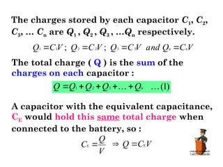
The charges storedby each capacitor C1, C2,
C3, … Cn are Q1 , Q2 , Q3 , …Qn respectively.
1 1 2 2 3 3 n n
; ;
Q C V Q C V Q C V and Q C V
The total charge ( Q ) is the sum of the
charges on each capacitor :
1 2 3 n (1)
Q Q Q Q Q
A capacitor with the equivalent capacitance,
CE would hold this same total charge when
connected to the battery, so :
E
Q
C
V
E
Q C V
17.
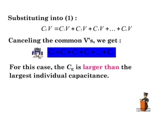
E 1 23 n
C V C V C V C V C V
Canceling the common V’s, we get :
E 1 2 3 n
C C C C C
Substituting into (1) :
For this case, the CE is larger than the
largest individual capacitance.
18.
Example 1
What isthe total capacitance in a, b and c ?
(a) (b) (c)
1 5 F
C
2 10 F
C
3 15 F
C
1 5 F
C
2 10 F
C
3 15 F
C
1 5 F
C
2 10 F
C
3 15 F
C
+ - + - + -
+
+
+
+ + +
+
+
+
-
-
-
- - -
-
-
-
19.
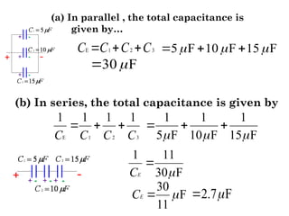
(a) In parallel, the total capacitance is
given by…
E 1 2 3
C C C C
5 F 10 F 15 F
30 F
(b) In series, the total capacitance is given by
E 1 2 3
1 1 1 1
C C C C
1 1 1
5 F 10 F 15 F
1 11
30 F
E
C
30
F
11
E
C
2.7 F
20.
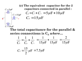
(c) The equivalentcapacitor for the 2
capacitors connected in parallel :
p 1 2
C C C
5 F 10 F
15 F
p
C
The total capacitance for the parallel &
series connections is CE where…
E p 3
1 1 1
C C C
1 1
15 F 15 F
2
15 F
7.5 F
15
F
2
E
C
21.
Example 2
1. Whatis the total capacitance in a, b and c ?
(a) (b) (c)
1 5 F
C
2 10 F
C
3 15 F
C
1 5 F
C
2 10 F
C
3 15 F
C
𝐶1=5𝜇F
2 10 F
C
3 15 F
C
+ - + - + -
+
+
+
+ + +
+
+
+
-
-
-
- - -
-
-
-
V = 9V V = 12V V = 24V
2. Find the potential difference across the capacitors
X, Y and Z .
3. Find the charges reside on the capacitors X, Y and Z .
22.
ASSESSMENT 1
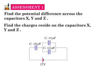
Find thepotential difference across the
capacitors X, Y and Z .
X 6 F
C
Y 1 F
C
Z 2 F
C
12V
Find the charges reside on the capacitors X,
Y and Z .
23.
The equivalent capacitancefor Y & Z
is CYZ where…
YZ Y Z
C C C
1 F 2 F
YZ 3 F
C
X 6 F
C
YZ 3 F
C
The equivalent capacitance for X, Y & Z :
E X YZ
1 1 1
C C C
1 1
6 F 3 F
1
2 F
E 2 F
C
E
C
24.
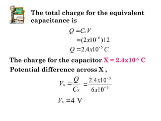
The total chargefor the equivalent
capacitance is
E
Q C V
12
)
10
2
( 6
x
C
x
Q 5
10
4
.
2
The charge for the capacitor X = 2.4x10⁻⁵
C
X
X
Q
V
C
Potential difference across X ,
6
5
10
6
10
4
.
2
x
x
X 4 V
V
25.
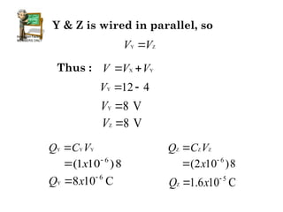
Y & Zis wired in parallel, so
Y Z
V V
Thus : X Y
V V V
Y 12 4
V
Y 8 V
V
Z 8 V
V
Y Y Y
Q C V
8
)
10
1
( 6
x
Y
6
8 10 C
Q x
Z Z Z
Q C V
8
)
10
2
( 6
x
Z
5
1.6 10 C
Q x
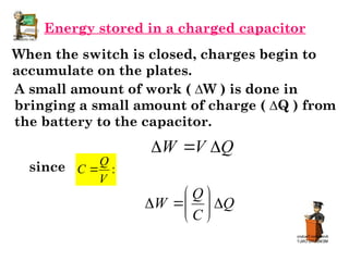
Energy stored ina charged capacitor
When the switch is closed, charges begin to
accumulate on the plates.
A small amount of work ( ∆W ) is done in
bringing a small amount of charge ( ∆Q ) from
the battery to the capacitor.
since
Q
V
W
:
V
Q
C
Q
C
Q
W
28.
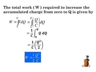
The total work( W ) required to increase the
accumulated charge from zero to Q is given by
C
Q
W
2
2
1
Q
VdQ
W
0 0
Q
Q
dQ
C
29.
We know, thus:
Q CV
can also be written as : , thus :
Q
C C
V
2
2
1
V
C
W
V
Q
W
2
1
The work done in charging the capacitor
appears as electric potential energy PE
stored in the capacitor.
Thus: Work done, W = Energy, PE
∆ 𝑷𝑬 ∆ 𝑷𝑬 ∆ 𝑷𝑬
30.
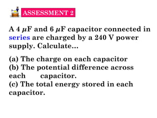
ASSESSMENT 2
A 4μF and 6 μF capacitor connected in
series are charged by a 240 V power
supply. Calculate…
(a) The charge on each capacitor
(b) The potential difference across
each capacitor.
(c) The total energy stored in each
capacitor.
31.
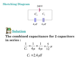
240V
4 F
6F
Solution
The combined capacitance for 2 capacitors
in series :
E
1 1 1
4 6
C
12
5
E 2.4 F
C
1
C 2
C
Sketching Diagram
32.
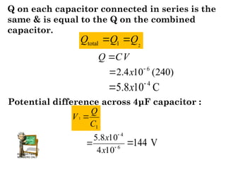
Q on eachcapacitor connected in series is the
same & is equal to the Q on the combined
capacitor.
V
C
Q
)
240
(
10
4
.
2 6
x
4
5.8 10 C
x
Potential difference across 4μF capacitor :
1
1
C
Q
V
6
4
10
4
10
8
.
5
x
x
144 V
2
total 1
Q Q Q
33.
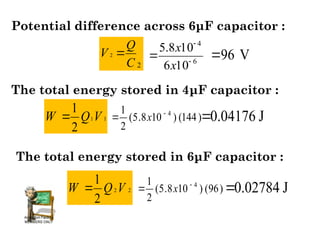
Potential difference across6μF capacitor :
2
2
C
Q
V
6
4
10
6
10
8
.
5
x
x
96 V
The total energy stored in 4μF capacitor :
1
1
2
1
V
Q
W )
144
(
)
10
8
.
5
(
2
1 4
x 0.04176 J
The total energy stored in 6μF capacitor :
2
2
2
1
V
Q
W )
96
(
)
10
8
.
5
(
2
1 4
x 0.02784 J
34.
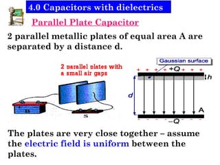
Parallel Plate Capacitor
2parallel metallic plates of equal area A are
separated by a distance d.
The plates are very close together – assume
the electric field is uniform between the
plates.
4.0 Capacitors with dielectrics
35.
Knowing that Q= CV, thus we have :
d
A
C
0
where…
ε0 : permittivity of free space
8.85x10⁻¹²
F m-1
A : area of the plate
d : distance between 2 plates
36.
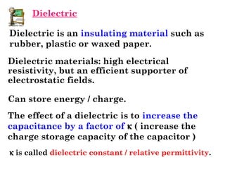
Dielectric is aninsulating material such as
rubber, plastic or waxed paper.
The effect of a dielectric is to increase the
capacitance by a factor of k ( increase the
charge storage capacity of the capacitor )
k is called dielectric constant / relative permittivity.
Dielectric materials: high electrical
resistivity, but an efficient supporter of
electrostatic fields.
Can store energy / charge.
Dielectric
37.
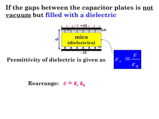
If the gapsbetween the capacitor plates is not
vacuum but filled with a dielectric
ε = εr ε0
mica
(dielectrics)
0
r
Permittivity of dielectric is given as
Rearrange:
38.
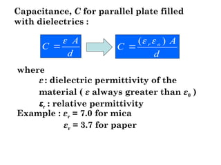
where
ε : dielectricpermittivity of the
material ( ε always greater than ε0 )
εr : relative permittivity
Example : εr = 7.0 for mica
εr = 3.7 for paper
d
A
C o
r )
(
Capacitance, C for parallel plate filled
with dielectrics :
d
A
C
39.
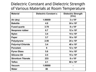
Dielectric Constant andDielectric Strength
of Various Materials at Room Temperature
Material Dielectric Constant k Dielectric Strength
(V/m)
Air (dry) 1.00059 3 x 10⁶
Bakelite 4.9 24 x 106
Fused quartz 3.78 8 x 10⁶
Neoprene rubber 6.7 12 x 106
Nylon 3.4 14 x 106
Paper 3.7 16 x 106
Polystyrene 2.56 24 x 106
Polyvinyl Chloride 3.4 40 x 106
Porcelain 6 12 x 106
Pyrex Glass 5.6 14 x 106
Silicone Oil 2.5 15 x 106
Strontium Titanate 233 8 x 10⁶
Teflon 2.1 60 x 106
Vacuum 1.00000 -
Water 80 -
40.
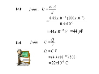
Example 1
A parallelplate capacitor consists of 2 plates
each with area 200 cm2
separated by a 0.4 cm
air gap.
(a) compute its capacitance
(b) if the capacitor is connected across a 500
V source, what are the charge on either
plate ?
Solution
Air gap – εr = 1.0 thus ε = ε0
A = 200 cm2
= 200x10-4
m2
d = 0.4 cm = 0.4x10⁻²
m
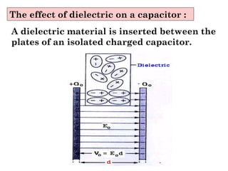
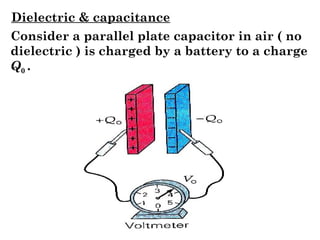
The effect ofdielectric on a capacitor :
A dielectric material is inserted between the
plates of an isolated charged capacitor.
43.
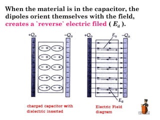
When the materialis in the capacitor, the
dipoles orient themselves with the field,
creates a `reverse` electric filed ( Ed ).
44.
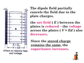
The dipole fieldpartially
cancels the field due to the
plate charges.
the net field ( E ) between the
plates is reduced – the voltage
across the plates ( V = Ed ) also
decreases.
Since the stored charge
remains the same, the
capacitance increases.
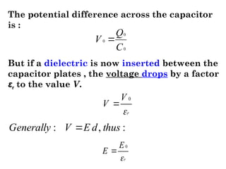
The potential differenceacross the capacitor
is :
0
0
0
C
Q
V
But if a dielectric is now inserted between the
capacitor plates , the voltage drops by a factor
εr to the value V.
r
V
V
0
r
E
E
0
:
,
: thus
d
E
V
Generally
47.
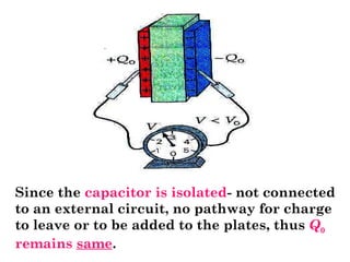
Since the capacitoris isolated- not connected
to an external circuit, no pathway for charge
to leave or to be added to the plates, thus Q0
remains same.
48.
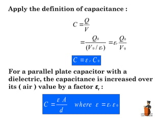
Apply the definitionof capacitance :
V
Q
C
)
/
( 0
0
r
V
Q
0
0
V
Q
r
0
C
C r
For a parallel plate capacitor with a
dielectric, the capacitance is increased over
its ( air ) value by a factor εr :
0
r
where
d
A
C
49.
PITFALL Prevention
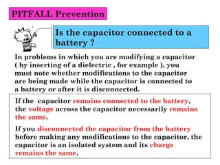
In problemsin which you are modifying a capacitor
( by inserting of a dielectric , for example ), you
must note whether modifications to the capacitor
are being made while the capacitor is connected to
a battery or after it is disconnected.
Is the capacitor connected to a
battery ?
If the capacitor remains connected to the battery,
the voltage across the capacitor necessarily remains
the same.
If you disconnected the capacitor from the battery
before making any modifications to the capacitor, the
capacitor is an isolated system and its charge
remains the same.
50.
Example 5
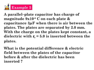
A parallel–platecapacitor has charge of
magnitude 9x10⁻⁶
C on each plate &
capacitance 3μF when there is air between the
plates. The plates are separated by 2.0 mm.
With the charge on the plates kept constant, a
dielectric with εr = 5.0 is inserted between the
plates.
What is the potential difference & electric
field between the plates of the capacitor
before & after the dielectric has been
inserted ?
51.
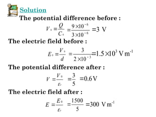
Solution
The potential differencebefore :
0
0
C
Q
V
6
6
10
3
10
9
3 V
The electric field before :
d
V
E
0
0 3
10
2
3
3 -1
1.5 10 Vm
The potential difference after :
r
V
V
0
5
3
0.6V
The electric field after :
r
E
E
0
5
1500
-1
300 Vm
52.
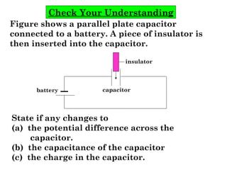
Check Your Understanding
Figureshows a parallel plate capacitor
connected to a battery. A piece of insulator is
then inserted into the capacitor.
State if any changes to
(a) the potential difference across the
capacitor.
(b) the capacitance of the capacitor
(c) the charge in the capacitor.
capacitor
insulator
battery
53.
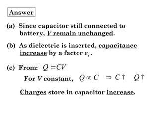
Answer
(a) Since capacitorstill connected to
battery, V remain unchanged.
(b) As dielectric is inserted, capacitance
increase by a factor εr .
(c) From: CV
Q
For V constant, C
Q
Q
C
Charges store in capacitor increase.
54.
Extra Example :A Partially Filled
Capacitor
Pictures from Serway & Beichner
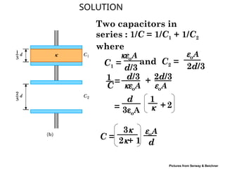
A parallel-plate capacitor with a plate separation d
has a capacitance Co in the absence of a dielectric.
What is the capacitance when a slab of dielectric
material of dielectric constant k and thickness d/3 is
inserted between the plates as shown.
55.
SOLUTION
Pictures from Serway& Beichner
Two capacitors in
series : 1/C = 1/C1 + 1/C2
where
keoA
C1 =
d/3
eoA
C2 =
2d/3
and
C
1 =
d/3
keoA
+ 2d/3
eoA
=
d
3eoA
1
k + 2
C =
3k
2k+ 1
eoA
d
56.
11/16/2025 Matriculation PhysicsSF027 63
End of Chapter 2
CAUTION !!! Capacitors are located inside of all laboratory equipment. They
come in many different shapes and sizes. Capacitors can remain energized and
produce harmful shocks long after a piece of equipment has been unplugged.