Downloaded 384 times


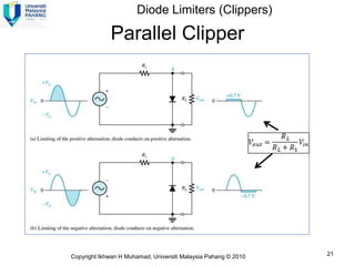
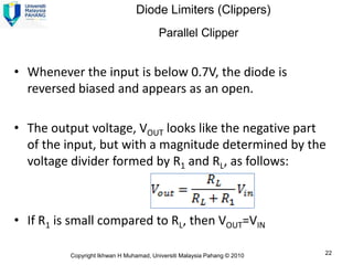


Here are the answers to the review questions: 1) The capacitor in a clamping circuit effectively acts as a battery by holding the DC level set during the clamping portion of the input cycle. 2) A +ve limiter only allows positive excursions of the input signal above a certain threshold, while a -ve limiter only allows negative excursions below a certain threshold. So a +ve limiter clips the positive portions and a -ve limiter clips the negative portions.