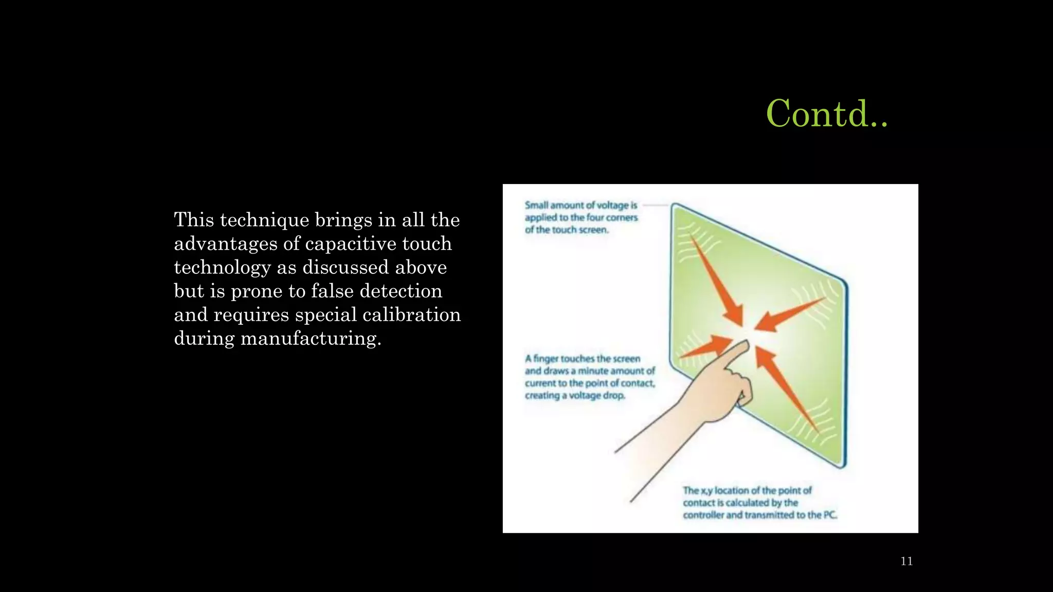
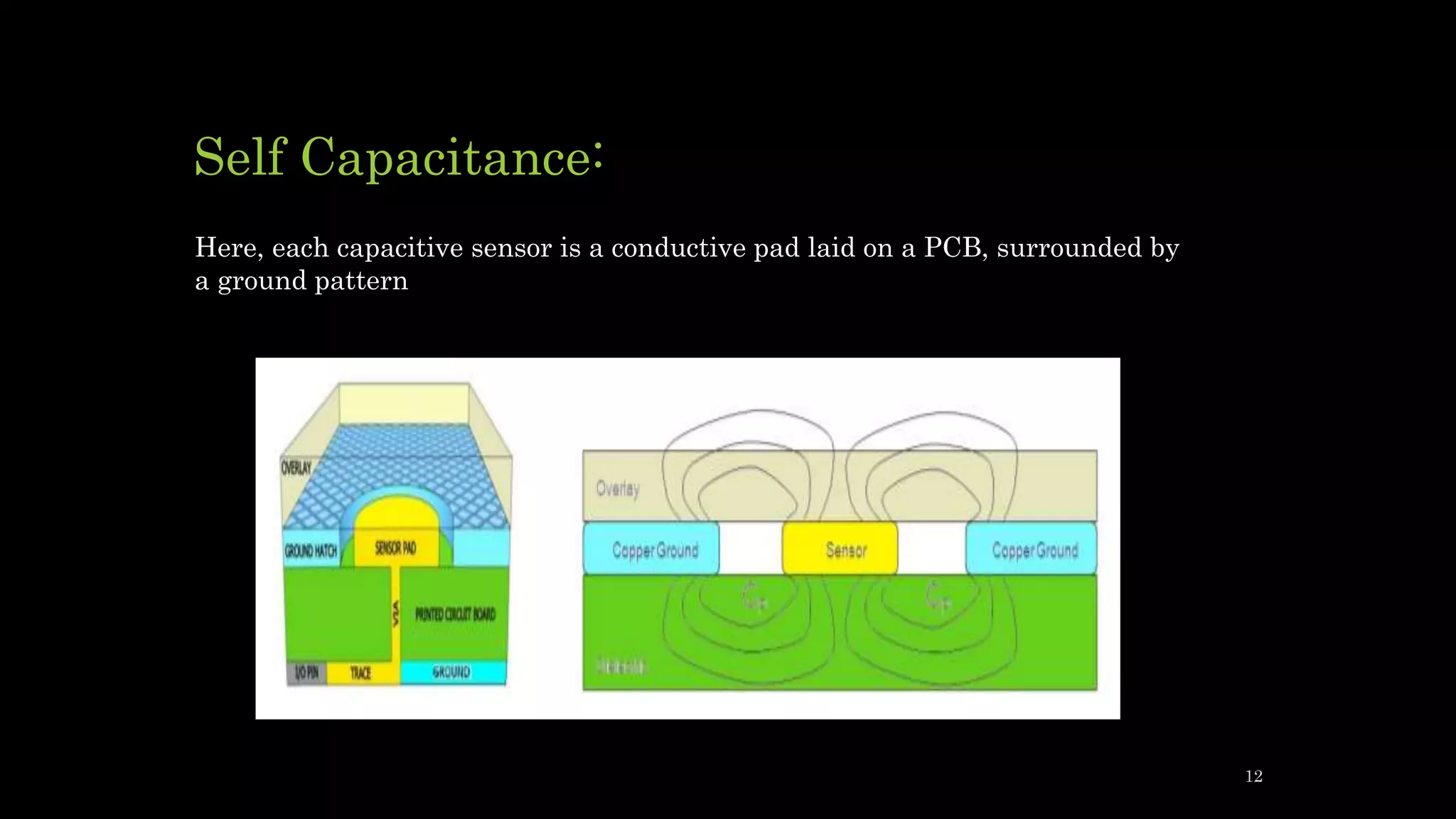
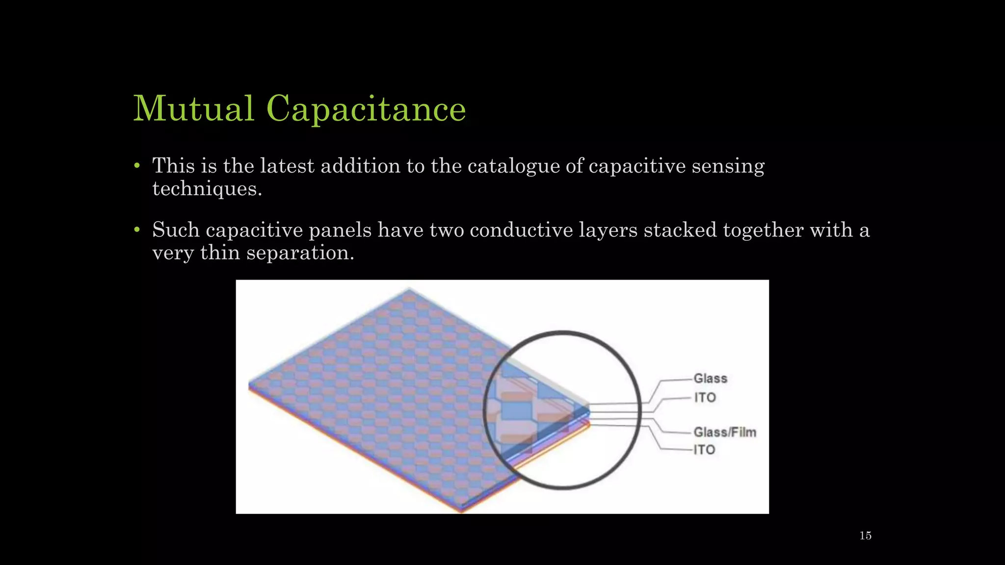
SlideShare a Scribd company logo
CAPACITIVE SENSING TECHNOLOGY
Karolinekersin E
Assistant professor
Capacitive sensing
• Capacitive sensing is becoming a popular technology to replace optical
detection methods and mechanical designs for applications like
proximity/gesture detection, material analysis, and liquid level sensing.
• The main advantages that capacitive sensing has over other detection
approaches are that it can sense different kinds of materials (skin, plastic,
metal, liquid),
• It is contactless and wear-free,
• It has the ability to sense up to a large distance with small sensor sizes,
• The PCB sensor is low cost, and it is a low power solution
2
Contd..
• Capacitive sensing (sometimes capacitance sensing) is a technology, based on
capacitive coupling, that can detect and measure anything that is conductive
or has a dielectric different from air.
• Many types of sensors use capacitive sensing, including sensors to detect and
measure proximity, pressure, position and displacement, force, humidity, fluid
level, and acceleration.
• Human interface devices based on capacitive sensing, such as trackpads, can
replace the computer mouse.
• Digital audio players, mobile phones, and tablet computers use capacitive
sensing touchscreens as input devices. Capacitive sensors can also replace
mechanical buttons.
• Capacitive sensing is a prevalent technology, for example, every smartphone
uses capacitive sensing within the screen to make it a touch screen
3
Capacitance Measurement Basics
• Capacitance is the ability of a capacitor to store an electrical charge.
• A common form – a parallel plate capacitor – the capacitance is calculated by C = Q / V,
where C is the capacitance related by the stored charge Q at a given voltage V.
• The capacitance (measured in Farads) of a parallel plate capacitor consists of two conductor
plates and is calculated by
• A is the area of the two plates (in meters)
• εr is the dielectric constant of the material between the plates
• ε0 is the permittivity of free space (8.85 x 10⁻¹² F/m)
• d is the separation between the plates (in meters)
4
Contd..
• The plates of a charged parallel plate capacitor carry equal but opposite
charge spread evenly over the surfaces of the plates.
• The electric field lines start from the higher voltage potential charged
plate and end at the lower voltage potential charged plate.
• The parallel plate equation ignores the fringing effect due to the
complexity of modeling the behavior but is a good approximation if the
distance (d) between the plates is small compared to the other dimensions
of the plates so the field in the capacitor over most of its area is uniform.
5
Contd..
• The fringing effect occurs near the edges of the plates, and depending on
the application, can affect the accuracy of measurements from the system.
• The density of the field lines in the fringe region is less than directly
underneath the plates since the field strength is proportional to the
density of the equipotential lines.
• This results in weaker field strength in the fringe region and a much
smaller contribution to the total measured capacitance
6
Parallel plate capacitor –Fringing effect
7
Capacitive sensing
• Capacitive sensing is a technology based on capacitive coupling that takes
the capacitance produced by the human body as the input.
• It allows a more reliable solution for applications to measure liquid levels,
material composition, mechanical buttons, and human-to-machine
interfaces.
• A basic capacitive sensor is anything metal or a conductor and detects
anything that is conductive or has a dielectric constant different from air
8
Types of capacitance
• A capacitive touch sensor is based on one of the following capacitance
types:
• Surface capacitance
• Projected Capacitance
These are subdivided again into two types
• Self capacitance
• Mutual capacitance
9
Surface Capacitance
• In this technology, glass is uniformly coated with a conductive layer.
• During operation, a voltage signal is applied to all four corners of the
panel, resulting in a uniform electrostatic field.
• When a human finger touches the panel, it forms a capacitance where
one plate is the conductive layer and the other being the human finger.
• Depending upon the location of the finger touch, current drawn from the
four corners will be different and thus the capacitance seen by those
corners will also be different.
• This difference can be used to determine the exact location of the touch
10
Contd..
This technique brings in all the
advantages of capacitive touch
technology as discussed above
but is prone to false detection
and requires special calibration
during manufacturing.
11
Self Capacitance:
Here, each capacitive sensor is a conductive pad laid on a PCB, surrounded by
a ground pattern
12
Contd..
• This sensor forms a parasitic capacitance Cp with the surrounding ground
pattern, and the electric field lines can be seen in the area above the
sensor.
• When a conductor like a finger enters the area above this sensor, it alters
the electric field lines and effectively adds a finger capacitance Cf to the
sensor
13
Contd..
• This results in an increase in capacitance of the sensor from Cp to Cp +
Cf.
• By continuously measuring the capacitance of the sensor(s) in the system
and looking for a sudden change in capacitance, a microcontroller can
determine when the finger was placed on the sensor.
• Here, the absolute value, or the parasitic capacitance of the sensor does
not matter.
• The microcontroller just looks for a sudden change in capacitance and if
this change is above a particular threshold, a finger presence is reported.
14
Mutual Capacitance
• This is the latest addition to the catalogue of capacitive sensing
techniques.
• Such capacitive panels have two conductive layers stacked together with a
very thin separation.
15
Contd..
• In this technology, when a finger touches the panel, the mutual
capacitance between the row and column is reduced.
• This reduction in capacitance is used to identify the presence of a finger.
16
Capacitive Sensor Topologies
The sensor topology depends on:
• Sensor-to-target distance
• Dielectric constant of target
• Desired sensitivity
17
Basic topologies of capacitive sensing
technology
Single
sensor or
isolated
sensor
Parallel
fingers
Parallel
plate
18
Single Sensor or proximity sensor
• Single sensor is used for Human Recognition.
• The single sensor design for human recognition uses the same fringe
capacitance principles as the parallel fingers topology except that the
human hand or finger substitutes the ground electrode.
• Since the human body is grounded, the fringing electric field lines stray
from the sensor to the hand as the hand approaches the sensor.
• This technique behaves similarly to the parallel plate equation since the
distance between the sensor and GND (hand) electrodes is the only
changing parameter.
19
Contd..
• The capacitance increases as the hand gets
closer to the sensor, but in a non-linear
way because of fringing effects.
• The presence of the shield electrode
underneath the sensor electrode helps
reduce EMI and parasitic capacitances
effects
20
Parallel Plate
• The parallel plate topology works exactly as
described by the parallel plate capacitor
equation.
• The high density of electric fields between the
two plates allows high sensitivity.
• Example applications for this topology are
material analysis and paper stack height
sensing.
21
Parallel Fingers
• The parallel fingers (GND-sensor) topology works under the principle of
fringing capacitance.
• High sensitivity along the z-axis of the sensors enables this topology to be
implemented in liquid level sensing applications.
• The electric field lines are more dominant near the edges between the
sensor and ground plates.
22
Contd..
23
• The capacitance calculations are not as
straightforward as the simple parallel plate
form but the sensitivity of the sensors
increases as sensor size increases (non-
linearly).
• A shield on the backside of the main sensor
and GND electrode provides directivity
towards the target.
DESIGN PARAMETERS- Parallel
fingers(liquid level sensing)
• Larger sensor size area increases
sensitivity and dynamic range of the
measurements.
• Minimize the gap between the sensor
and the water to allow sufficient
sensitivity or increase sensor area.
• Increasing the gap spacing between
the sensor and GND electrode slightly
increases sensitivity and dynamic
range.
• Only valid if the spacing of the
electrodes to the water is minimized.
• Use the Out-Of-Phase technique to
mitigate interference from grounded
objects like the human hand so
capacitance measurements are not
severely affected.
24
Design parameters- Parallel plate
• Larger sensor size area increases sensitivity and dynamic range of the
measurements, but higher chance for the sensor to be affected by any
noise or interference in the surrounding environment.
• Minimizing the distance between the sensor and shield electrode ensures
better coupling and effectiveness, but sensitivity and dynamic range
decreases.
• The parallel fingers approach used for liquid level sensing works best
when the target is ungrounded.
• The isolated sensor approach works best when the target is grounded.
25
Active Shielding
• An active shield coupling with the sensor helps mitigate interference and
parasitic capacitances seen along the sensor signal path from the
electrode to the input of the FDC1004.
• It also helps to focus the target direction in a specific area.
• A shield electrode can be paired with the sensor electrode in several ways
and affects the measurement parameters differently compared to the
absence of a shield electrode.
26
Contd..
• A shield the same size as the sensor electrode placed directly underneath
the sensor.
• A shield larger than the sensor electrode placed directly underneath the
sensor.
• A shield ring wrapped around the top side adjacent to the sensor with a
shield underneath the sensor.
27
Contd..
• The shield blocks interference from the bottom and side proximity of the
sensor.
• As the shield size increases, the effect from interference decreases but the
sensitivity and dynamic range of the capacitance measurements for top,
side, and bottom proximity also decreases.
• Minimizing the distance between the sensor and shield electrode ensures
better coupling and effectiveness.
• The shield must be sized accordingly, depending on how much margin is
allocated for interference and parasitics.
28
Different types of noise
A capacitive sensing system is mainly susceptible to noise generated from
the following three sources:
Radiated noise
• Any operating circuitry radiates energy that can potentially create
problems with the operation of other circuits in its vicinity.
• Capacitive sensing buttons constitute only the user interface part of any
system, and generally there is much circuitry sitting behind the user
interface.
• This nearby circuitry can also radiate noise if not properly designed.
Sources of noise can be the LCD (Liquid Crystal Display), switching power
supplies, mobile phone, Wi-Fi radio, etc.
29
Conducted noise
• A noisy power supply is the most common source of conducted noise.
• The increasing demand of low cost implementations forces developers to
use less expensive supplies which in turn generate more noise.
• This can adversely affect the operation of the sensor.
• A human body touching the sensor can also couple a 50/60Hz common
mode noise into the system.
30
Environmental changes
• Changes in environmental parameters such as humidity, temperature,
and device aging also change the capacitance of the sensor.
• Such unwanted changes can also be termed as noise.
31
Multiple techniques for achieving a good snr
Tuning (Auto or Manual)
• Calibrate the device during the design phase to ensure that it exhibits a
minimum of 5:1 SNR for fail-safe operation.
• Using some software overhead, this manual tuning effort can be switched
to auto-tuning wherein the device calibrates itself in the field to ensure
that it achieves the minimum SNR required.
• Cypress’ SmartSense solution is an example of such an innovative
technique.
32
Contd..
Auto correction
Gradual changes in capacitance because of temperature, humidity, or
component aging can be compensated by monitoring the counts obtained
(digital representation of capacitance) in firmware and updating the
reference signal with the gradual change observed.
• Note that in the case of auto-calibrating solutions, it is also possible to
recalibrate the system if the gradual change in counts exceeds a
particular threshold.
Layout
• A proper schematic and PCB layout is address all the problems mentioned
above.
33
Filters
• Software filters used to process the digital counts obtained can also be
used to improve the SNR.
• The use of filters increases response time but improves SNR dramatically.
• Depending upon system requirements like response time and power
consumption, the use of software filters may be feasible
34
ELECTROSTATIC ACTUATORS
• Electrostatic actuation makes use of electrostatic force induced by the
potential difference between a micro actuator and its electrode.
• As its applied voltage increases, higher electrostatic force results in more
displacement.
• For most cases, both DC bias and AC signal are used to displace a micro
actuator at the same time.
• Although the dynamics of a micro actuator can be linearized within small
displacement, an electrostatic micro actuator is inherently nonlinear,
making it more difficult for feedback control to be implemented while
achieving a large displacement.
35
• Although electrostatic actuation requires higher actuation voltage than
that of other actuation methods, electrostatic actuation does not require
complicated fabrication methods, piezoelectric materials or ferromagnetic
materials deposited on a micro actuator.
• In addition, most electrostatic actuators require very small current,
depending on the size and geometry of micro actuators.
• In spite of this limited operation range due to the pull-in effect, nonlinear
behavior in response to applied voltage, and high actuation voltage,
electrostatic actuation is one of the most popular actuation methods
because of its fast response time (less than 0.1 ms), low power
consumption, and the easiness of integration and testing with electrical
control circuitry.
36
Micromotor
One of the first electrostatic actuators was a micromotor.
Consider the principle of operation:
• Central rotor has one charge.
• Radial stator poles have opposite charge.
• Six stator phases (pair of poles) as shown below, are turned on and off in a
sequence to cause the rotor to turn.
37
Capacitive pressure sensor
• Capacitive pressure sensors measure pressure by detecting changes in
electrical capacitance caused by the movement of a diaphragm.
• A capacitor consists of two parallel conducting plates separated by a small
gap.
38
Working principle
• Changing any of the variables will cause a corresponding change in the
capacitance. The easiest one to control is the spacing.
• This can be done by making one or both of the plates a diaphragm that is
deflected by changes in pressure.
• Typically, one electrode is a pressure sensitive diaphragm and the other is
fixed. An example of a capacitive pressure sensor is shown to the right.
• An easy way of measuring the change in capacitance is to make it part of
a tuned circuit, typically consisting of the capacitive sensor plus an
inductor.
• This can either change the frequency of an oscillator or the AC coupling of
a resonant circuit.
39
Construction
40
Contd..
• The diaphragm can be constructed from a variety of materials, such as
plastic, glass, silicon or ceramic, to suit different applications.
• The capacitance of the sensor is typically around 50 to 100 pF, with the
change being a few picofarads.
• The stiffness and strength of the material can be chosen to provide a
range of sensitivities and operating pressures.
• To get a large signal, the sensor may need to be fairly large, which can
limit the frequency range of operation.
• However, smaller diaphragms are more sensitive and have a faster
response time.
41
Contd..
• A large thin diaphragm may be sensitive to noise from vibration (after all,
the same basic principle is used to make condenser microphones)
particularly at low pressures.
• Thicker diaphragms are used in high-pressure sensors and to ensure
mechanical strength.
• Sensors with full-scale pressure up to 5,000 psi can readily be constructed
by controlling the diaphragm thickness.
42
Contd..
• By choosing materials for the capacitor plates that have a low coefficient
of thermal expansion, it’s possible to make sensors with very low
sensitivity to temperature change.
• The structure also needs to have low hysteresis to ensure accuracy and
repeatability of measurements.
• Because the diaphragm itself is the sensing element, there are no issues
with extra components being bonded to the diaphragm, so capacitive
sensors are able to operate at higher temperatures than some other types
of sensor.
43
Diagram of Pressure sensor
44
Function
• The change in capacitance can be measured by connecting the sensor in a
frequency-dependent circuit such as an oscillator or an LC tank circuit. In
both cases, the resonant frequency of the circuit will change as the
capacitance changes with pressure.
• An oscillator requires some extra electronic components and a power
supply. A resonant LC circuit can be used as a passive sensor, without its
own source of power.
• The dielectric constant of the material between the plates may change
with pressure or temperature and this can also be a source of errors.
45
Contd..
• The relative permittivity of air, and most other gasses, increases with
pressure so this will slightly increase the capacitance change with
pressure.
• Absolute pressure sensors, which have a vacuum between the plates,
behave ideally in this respect.
• A more linear sensor can be constructed by using ‘touch mode’ where the
diaphragm makes contact with the opposite plate (with a thin insulating
layer in between) throughout the normal operating range (as shown to the
right). The geometry of this structure results in a more linear output
signal.
• This type of sensor is also more robust and able to cope with a larger over-
pressure. This makes it more suited to industrial environments. However,
this structure is more prone to hysteresis because of friction between the
two surfaces.
46
Design
• The electronics for measuring and conditioning the signal need to be
placed close to the sensing element to minimise the effect of stray
capacitance.
• Because they can be incorporated as components in high-frequency tuned
circuits, capacitive sensors are well suited for wireless measurement.
• In the case of passive sensors an external antenna can be used to provide
a signal to stimulate the tuned circuit and so measure the change in
resonance frequency (see diagram to the left). This makes them suitable
for medical devices that need to be implanted.
• Alternatively, for an active sensor, the frequency generated by the
oscillator can be picked up by an antenna.
47
Design
48
Applications
• Capacitive pressure sensors are often used to measure gas or liquid
pressures in jet engines, car tyres, the human body and many other
places.
• But they can also be used as tactile sensors in wearable devices or to
measure the pressure applied to a switch or keyboard.
• They are particularly versatile, in part due to their mechanical simplicity,
so can be used in demanding environments.
• Capacitive sensors can be used for absolute, gauge, relative or differential
pressure measurements.
•
49
MEMS pressure sensor
• Microelectromechanical systems (MEMS) devices combine small
mechanical and electronic components on a silicon chip.
• The fabrication techniques used for creating transistors, interconnect and
other components on an integrated circuit (IC) can also be used to
construct mechanical components such as springs, deformable
membranes, vibrating structures, valves, gears and levers.
• This technology can be used to make a variety of sensors including several
types of pressure sensor.
• It enables the combination of accurate sensors, powerful processing and
wireless communication (for example, Wi-Fi or Bluetooth) on a single IC.
• Large numbers of devices can be made at the same time so they benefit
from the same scaling advantages and cost efficiencies as traditional ICs.
50
MEMS capacitive pressure sensors
51
Contd..
• To create a capacitive sensor, conducting layers are deposited on the
diaphragm and the bottom of a cavity to create a capacitor.
• The capacitance is typically a few picofarads.
• Deformation of the diaphragm changes the spacing between the
conductors and hence changes the capacitance (see right).
• The change can be measured by including the sensor in a tuned circuit,
which changes its frequency with changing pressure.
52
Contd..
• The sensor can be used with electronic components on the chip to create
an oscillator, which generates the output signal.
• Because of the difficulty of fabricating large inductances on silicon, this
will usually be based on an RC circuit.
• This approach is well suited for wireless readout because it generates a
high frequency signal that can be detected with a suitable external
antenna.
• Alternatively, the capacitance can be measured more directly by
measuring the time taken to charge the capacitor from a current source.
This can be compared with a reference capacitor to account for
manufacturing tolerance and to reduce thermal effects
53
Reference
• https://www.avnet.com/wps/portal/abacus/solutions/technologies/sensors/p
ressure-sensors/core-technologies/capacitive
• https://www.avnet.com/wps/portal/abacus/solutions/technologies/sensors/p
ressure-sensors/core-technologies/mems/
• https://www.ti.com/lit/an/snoa927/snoa927.pdf?ts=1600963663107&ref_url
=https%253A%252F%252Fwww.google.com%252F
54
THANK YOU

More Related Content

What's hot

Force sensors presentation
Force sensors presentationForce sensors presentation
Force sensors presentationAhmad El Tawil
 
Capacitive sensors
Capacitive sensorsCapacitive sensors
Capacitive sensorsYasir Hashmi
 
Optical sensors and their applications
Optical sensors and their applicationsOptical sensors and their applications
Optical sensors and their applicationsSaumya Ranjan Behura
 
Photoelectric transducer
Photoelectric transducerPhotoelectric transducer
Photoelectric transducervickeysv
 
Ultrasonic transducers
Ultrasonic transducersUltrasonic transducers
Ultrasonic transducersKundan Gupta
 
Giant magnetoresistance
Giant magnetoresistanceGiant magnetoresistance
Giant magnetoresistancejamilahmedawan
 
Data acquisition system
Data acquisition systemData acquisition system
Data acquisition systemAmol Dudhate
 
Capacitive sensor
Capacitive sensorCapacitive sensor
Capacitive sensorAzlin lolin
 
Micro electro-mechanical-systems-based-sensors
Micro electro-mechanical-systems-based-sensorsMicro electro-mechanical-systems-based-sensors
Micro electro-mechanical-systems-based-sensorsMuhammad Ali Amjad
 
Pressure sensor Measurement
Pressure  sensor Measurement Pressure  sensor Measurement
Pressure sensor Measurement marcoReud
 
Successive Approximation ADC
Successive Approximation ADC Successive Approximation ADC
Successive Approximation ADC AbhayDhupar
 
Carrier and chopper amplifiers
Carrier and chopper amplifiers Carrier and chopper amplifiers
Carrier and chopper amplifiers BharathasreejaG
 
Modulation of light
Modulation of lightModulation of light
Modulation of lightCKSunith1
 

What's hot (20)

Force sensors presentation
Force sensors presentationForce sensors presentation
Force sensors presentation
 
Capacitive sensors
Capacitive sensorsCapacitive sensors
Capacitive sensors
 
Digital transducer
Digital transducerDigital transducer
Digital transducer
 
Magnetic sensors
Magnetic sensorsMagnetic sensors
Magnetic sensors
 
Optical sensors and their applications
Optical sensors and their applicationsOptical sensors and their applications
Optical sensors and their applications
 
Lvdt
LvdtLvdt
Lvdt
 
Sensors
SensorsSensors
Sensors
 
Photoelectric transducer
Photoelectric transducerPhotoelectric transducer
Photoelectric transducer
 
Ultrasonic transducers
Ultrasonic transducersUltrasonic transducers
Ultrasonic transducers
 
Giant magnetoresistance
Giant magnetoresistanceGiant magnetoresistance
Giant magnetoresistance
 
Data acquisition system
Data acquisition systemData acquisition system
Data acquisition system
 
Sensors
SensorsSensors
Sensors
 
Capacitive sensor
Capacitive sensorCapacitive sensor
Capacitive sensor
 
Micro electro-mechanical-systems-based-sensors
Micro electro-mechanical-systems-based-sensorsMicro electro-mechanical-systems-based-sensors
Micro electro-mechanical-systems-based-sensors
 
Pressure sensor Measurement
Pressure  sensor Measurement Pressure  sensor Measurement
Pressure sensor Measurement
 
sensors (It`s type)
sensors (It`s type)sensors (It`s type)
sensors (It`s type)
 
Successive Approximation ADC
Successive Approximation ADC Successive Approximation ADC
Successive Approximation ADC
 
Carrier and chopper amplifiers
Carrier and chopper amplifiers Carrier and chopper amplifiers
Carrier and chopper amplifiers
 
Acoustic sensors
Acoustic sensorsAcoustic sensors
Acoustic sensors
 
Modulation of light
Modulation of lightModulation of light
Modulation of light
 

Similar to Capacitive sensing technology

Seminar Report - Capacitive Sensors
Seminar Report - Capacitive SensorsSeminar Report - Capacitive Sensors
Seminar Report - Capacitive SensorsTarun Nekkanti
 
Control capacitive measurement
Control capacitive measurementControl capacitive measurement
Control capacitive measurementAzlin lolin
 
Sensors for Engineering Applications
Sensors for Engineering ApplicationsSensors for Engineering Applications
Sensors for Engineering Applicationsvenkatasuman1983
 
Energy Efficient and Secure Intrusion Detection for Maximum Coverage in WSN
Energy Efficient and Secure Intrusion Detection for Maximum Coverage in WSNEnergy Efficient and Secure Intrusion Detection for Maximum Coverage in WSN
Energy Efficient and Secure Intrusion Detection for Maximum Coverage in WSNAmairullah Khan Lodhi
 
Electrical Pressure Measuring Devices
Electrical Pressure Measuring DevicesElectrical Pressure Measuring Devices
Electrical Pressure Measuring DevicesMaria Romina Angustia
 
ECT SystemElectrical Capacitive tomography is used to find the p.docx
ECT SystemElectrical Capacitive tomography is used to find the p.docxECT SystemElectrical Capacitive tomography is used to find the p.docx
ECT SystemElectrical Capacitive tomography is used to find the p.docxjack60216
 
Sensors and transducers 1.ppt
Sensors and transducers 1.pptSensors and transducers 1.ppt
Sensors and transducers 1.pptMdJunaid20
 
proximity sensors report
proximity sensors reportproximity sensors report
proximity sensors reportRavi Raj
 
SymposiumPoster [Read-Only]
SymposiumPoster [Read-Only]SymposiumPoster [Read-Only]
SymposiumPoster [Read-Only]Eric Tsai
 
2012 METU Lecture 2 Precision Sensors for Measurement of Strain Displacement ...
2012 METU Lecture 2 Precision Sensors for Measurement of Strain Displacement ...2012 METU Lecture 2 Precision Sensors for Measurement of Strain Displacement ...
2012 METU Lecture 2 Precision Sensors for Measurement of Strain Displacement ...omidsalangi1
 
Robot sensors.pptx
Robot sensors.pptxRobot sensors.pptx
Robot sensors.pptxNeenuAntony9
 
53_36765_ME591_2012_1__1_1_SENSORS.pdf
53_36765_ME591_2012_1__1_1_SENSORS.pdf53_36765_ME591_2012_1__1_1_SENSORS.pdf
53_36765_ME591_2012_1__1_1_SENSORS.pdfDrPArivalaganASSTPRO
 

Similar to Capacitive sensing technology (20)

Seminar Report - Capacitive Sensors
Seminar Report - Capacitive SensorsSeminar Report - Capacitive Sensors
Seminar Report - Capacitive Sensors
 
Control capacitive measurement
Control capacitive measurementControl capacitive measurement
Control capacitive measurement
 
Proximity sensors
Proximity sensorsProximity sensors
Proximity sensors
 
electromagnet
electromagnetelectromagnet
electromagnet
 
Gaurav seminar
Gaurav seminarGaurav seminar
Gaurav seminar
 
SENSORS_UNIT-2.pdf
SENSORS_UNIT-2.pdfSENSORS_UNIT-2.pdf
SENSORS_UNIT-2.pdf
 
Sensors for Engineering Applications
Sensors for Engineering ApplicationsSensors for Engineering Applications
Sensors for Engineering Applications
 
Energy Efficient and Secure Intrusion Detection for Maximum Coverage in WSN
Energy Efficient and Secure Intrusion Detection for Maximum Coverage in WSNEnergy Efficient and Secure Intrusion Detection for Maximum Coverage in WSN
Energy Efficient and Secure Intrusion Detection for Maximum Coverage in WSN
 
sensors
sensorssensors
sensors
 
Capacitive Transducer.pdf
Capacitive Transducer.pdfCapacitive Transducer.pdf
Capacitive Transducer.pdf
 
Electrical Pressure Measuring Devices
Electrical Pressure Measuring DevicesElectrical Pressure Measuring Devices
Electrical Pressure Measuring Devices
 
ECT SystemElectrical Capacitive tomography is used to find the p.docx
ECT SystemElectrical Capacitive tomography is used to find the p.docxECT SystemElectrical Capacitive tomography is used to find the p.docx
ECT SystemElectrical Capacitive tomography is used to find the p.docx
 
Sensors and transducers 1.ppt
Sensors and transducers 1.pptSensors and transducers 1.ppt
Sensors and transducers 1.ppt
 
proximity sensors report
proximity sensors reportproximity sensors report
proximity sensors report
 
SymposiumPoster [Read-Only]
SymposiumPoster [Read-Only]SymposiumPoster [Read-Only]
SymposiumPoster [Read-Only]
 
Touch sensors SIMAL
Touch sensors SIMALTouch sensors SIMAL
Touch sensors SIMAL
 
2012 METU Lecture 2 Precision Sensors for Measurement of Strain Displacement ...
2012 METU Lecture 2 Precision Sensors for Measurement of Strain Displacement ...2012 METU Lecture 2 Precision Sensors for Measurement of Strain Displacement ...
2012 METU Lecture 2 Precision Sensors for Measurement of Strain Displacement ...
 
Robot sensors.pptx
Robot sensors.pptxRobot sensors.pptx
Robot sensors.pptx
 
53_36765_ME591_2012_1__1_1_SENSORS.pdf
53_36765_ME591_2012_1__1_1_SENSORS.pdf53_36765_ME591_2012_1__1_1_SENSORS.pdf
53_36765_ME591_2012_1__1_1_SENSORS.pdf
 
resistive.pptx
resistive.pptxresistive.pptx
resistive.pptx
 

More from karoline Enoch

Thermogravimetric analysis.pptx
Thermogravimetric analysis.pptxThermogravimetric analysis.pptx
Thermogravimetric analysis.pptxkaroline Enoch
 
UV VISIBLE SPECTROSCOPY
UV VISIBLE SPECTROSCOPYUV VISIBLE SPECTROSCOPY
UV VISIBLE SPECTROSCOPYkaroline Enoch
 
Nanotribolgy for medical devices
Nanotribolgy for medical devicesNanotribolgy for medical devices
Nanotribolgy for medical deviceskaroline Enoch
 
Protein based nanostructures for biomedical applications
Protein based nanostructures for biomedical applications Protein based nanostructures for biomedical applications
Protein based nanostructures for biomedical applications karoline Enoch
 
Schering bridge and its derivation
Schering bridge and its derivationSchering bridge and its derivation
Schering bridge and its derivationkaroline Enoch
 
Maxwell bridge and its types
Maxwell bridge and its types Maxwell bridge and its types
Maxwell bridge and its types karoline Enoch
 
Kelvin bridge and kelvin double bridge
Kelvin bridge and kelvin double bridge Kelvin bridge and kelvin double bridge
Kelvin bridge and kelvin double bridge karoline Enoch
 
Dc bridge types ,derivation and its application
Dc bridge types ,derivation and its applicationDc bridge types ,derivation and its application
Dc bridge types ,derivation and its applicationkaroline Enoch
 
Ac bridge and its application
Ac bridge and its application Ac bridge and its application
Ac bridge and its application karoline Enoch
 
Photodynamic therapy and mechanism
Photodynamic therapy and mechanismPhotodynamic therapy and mechanism
Photodynamic therapy and mechanismkaroline Enoch
 
Preamplifier and impedance matching circuits
Preamplifier and impedance matching circuitsPreamplifier and impedance matching circuits
Preamplifier and impedance matching circuitskaroline Enoch
 
Photo theraphy ,principle and mechanism
Photo theraphy ,principle and mechanismPhoto theraphy ,principle and mechanism
Photo theraphy ,principle and mechanismkaroline Enoch
 
Lasers in opthalmology
Lasers in opthalmologyLasers in opthalmology
Lasers in opthalmologykaroline Enoch
 
Photolithography and its procedure
Photolithography and its procedurePhotolithography and its procedure
Photolithography and its procedurekaroline Enoch
 
Piezoelectric transducer and its working
Piezoelectric transducer and its workingPiezoelectric transducer and its working
Piezoelectric transducer and its workingkaroline Enoch
 
Photoelectric transducers and its classification
Photoelectric transducers and its classificationPhotoelectric transducers and its classification
Photoelectric transducers and its classificationkaroline Enoch
 
Strain gauge as pressure transducers
Strain gauge as pressure transducersStrain gauge as pressure transducers
Strain gauge as pressure transducerskaroline Enoch
 

More from karoline Enoch (20)

Thermogravimetric analysis.pptx
Thermogravimetric analysis.pptxThermogravimetric analysis.pptx
Thermogravimetric analysis.pptx
 
UV VISIBLE SPECTROSCOPY
UV VISIBLE SPECTROSCOPYUV VISIBLE SPECTROSCOPY
UV VISIBLE SPECTROSCOPY
 
Nanotribolgy for medical devices
Nanotribolgy for medical devicesNanotribolgy for medical devices
Nanotribolgy for medical devices
 
Protein based nanostructures for biomedical applications
Protein based nanostructures for biomedical applications Protein based nanostructures for biomedical applications
Protein based nanostructures for biomedical applications
 
Schering bridge and its derivation
Schering bridge and its derivationSchering bridge and its derivation
Schering bridge and its derivation
 
Maxwell bridge and its types
Maxwell bridge and its types Maxwell bridge and its types
Maxwell bridge and its types
 
Kelvin bridge and kelvin double bridge
Kelvin bridge and kelvin double bridge Kelvin bridge and kelvin double bridge
Kelvin bridge and kelvin double bridge
 
Dc bridge types ,derivation and its application
Dc bridge types ,derivation and its applicationDc bridge types ,derivation and its application
Dc bridge types ,derivation and its application
 
Ac bridge and its application
Ac bridge and its application Ac bridge and its application
Ac bridge and its application
 
Photodynamic therapy and mechanism
Photodynamic therapy and mechanismPhotodynamic therapy and mechanism
Photodynamic therapy and mechanism
 
Preamplifier and impedance matching circuits
Preamplifier and impedance matching circuitsPreamplifier and impedance matching circuits
Preamplifier and impedance matching circuits
 
Photo theraphy ,principle and mechanism
Photo theraphy ,principle and mechanismPhoto theraphy ,principle and mechanism
Photo theraphy ,principle and mechanism
 
Lasers in opthalmology
Lasers in opthalmologyLasers in opthalmology
Lasers in opthalmology
 
Lasers in urology
Lasers in urologyLasers in urology
Lasers in urology
 
Lasers in dermatology
Lasers in dermatologyLasers in dermatology
Lasers in dermatology
 
Lasers in dentistry
Lasers in dentistryLasers in dentistry
Lasers in dentistry
 
Photolithography and its procedure
Photolithography and its procedurePhotolithography and its procedure
Photolithography and its procedure
 
Piezoelectric transducer and its working
Piezoelectric transducer and its workingPiezoelectric transducer and its working
Piezoelectric transducer and its working
 
Photoelectric transducers and its classification
Photoelectric transducers and its classificationPhotoelectric transducers and its classification
Photoelectric transducers and its classification
 
Strain gauge as pressure transducers
Strain gauge as pressure transducersStrain gauge as pressure transducers
Strain gauge as pressure transducers
 

Recently uploaded

Explosives Industry manufacturing process.pdf
Explosives Industry manufacturing process.pdfExplosives Industry manufacturing process.pdf
Explosives Industry manufacturing process.pdf884710SadaqatAli
 
Peek implant persentation - Copy (1).pdf
Peek implant persentation - Copy (1).pdfPeek implant persentation - Copy (1).pdf
Peek implant persentation - Copy (1).pdfAyahmorsy
 
ASME IX(9) 2007 Full Version .pdf
ASME IX(9)  2007 Full Version       .pdfASME IX(9)  2007 Full Version       .pdf
ASME IX(9) 2007 Full Version .pdfAhmedHussein950959
 
A CASE STUDY ON ONLINE TICKET BOOKING SYSTEM PROJECT.pdf
A CASE STUDY ON ONLINE TICKET BOOKING SYSTEM PROJECT.pdfA CASE STUDY ON ONLINE TICKET BOOKING SYSTEM PROJECT.pdf
A CASE STUDY ON ONLINE TICKET BOOKING SYSTEM PROJECT.pdfKamal Acharya
 
ONLINE VEHICLE RENTAL SYSTEM PROJECT REPORT.pdf
ONLINE VEHICLE RENTAL SYSTEM PROJECT REPORT.pdfONLINE VEHICLE RENTAL SYSTEM PROJECT REPORT.pdf
ONLINE VEHICLE RENTAL SYSTEM PROJECT REPORT.pdfKamal Acharya
 
NO1 Pandit Black Magic Removal in Uk kala jadu Specialist kala jadu for Love ...
NO1 Pandit Black Magic Removal in Uk kala jadu Specialist kala jadu for Love ...NO1 Pandit Black Magic Removal in Uk kala jadu Specialist kala jadu for Love ...
NO1 Pandit Black Magic Removal in Uk kala jadu Specialist kala jadu for Love ...Amil baba
 
Online resume builder management system project report.pdf
Online resume builder management system project report.pdfOnline resume builder management system project report.pdf
Online resume builder management system project report.pdfKamal Acharya
 
Natalia Rutkowska - BIM School Course in Kraków
Natalia Rutkowska - BIM School Course in KrakówNatalia Rutkowska - BIM School Course in Kraków
Natalia Rutkowska - BIM School Course in Krakówbim.edu.pl
 
Introduction to Machine Learning Unit-4 Notes for II-II Mechanical Engineering
Introduction to Machine Learning Unit-4 Notes for II-II Mechanical EngineeringIntroduction to Machine Learning Unit-4 Notes for II-II Mechanical Engineering
Introduction to Machine Learning Unit-4 Notes for II-II Mechanical EngineeringC Sai Kiran
 
Arduino based vehicle speed tracker project
Arduino based vehicle speed tracker projectArduino based vehicle speed tracker project
Arduino based vehicle speed tracker projectRased Khan
 
BRAKING SYSTEM IN INDIAN RAILWAY AutoCAD DRAWING
BRAKING SYSTEM IN INDIAN RAILWAY AutoCAD DRAWINGBRAKING SYSTEM IN INDIAN RAILWAY AutoCAD DRAWING
BRAKING SYSTEM IN INDIAN RAILWAY AutoCAD DRAWINGKOUSTAV SARKAR
 
Pharmacy management system project report..pdf
Pharmacy management system project report..pdfPharmacy management system project report..pdf
Pharmacy management system project report..pdfKamal Acharya
 
RESORT MANAGEMENT AND RESERVATION SYSTEM PROJECT REPORT.pdf
RESORT MANAGEMENT AND RESERVATION SYSTEM PROJECT REPORT.pdfRESORT MANAGEMENT AND RESERVATION SYSTEM PROJECT REPORT.pdf
RESORT MANAGEMENT AND RESERVATION SYSTEM PROJECT REPORT.pdfKamal Acharya
 
Digital Signal Processing Lecture notes n.pdf
Digital Signal Processing Lecture notes n.pdfDigital Signal Processing Lecture notes n.pdf
Digital Signal Processing Lecture notes n.pdfAbrahamGadissa
 
Democratizing Fuzzing at Scale by Abhishek Arya
Democratizing Fuzzing at Scale by Abhishek AryaDemocratizing Fuzzing at Scale by Abhishek Arya
Democratizing Fuzzing at Scale by Abhishek Aryaabh.arya
 
Cloud-Computing_CSE311_Computer-Networking CSE GUB BD - Shahidul.pptx
Cloud-Computing_CSE311_Computer-Networking CSE GUB BD - Shahidul.pptxCloud-Computing_CSE311_Computer-Networking CSE GUB BD - Shahidul.pptx
Cloud-Computing_CSE311_Computer-Networking CSE GUB BD - Shahidul.pptxMd. Shahidul Islam Prodhan
 
Top 13 Famous Civil Engineering Scientist
Top 13 Famous Civil Engineering ScientistTop 13 Famous Civil Engineering Scientist
Top 13 Famous Civil Engineering Scientistgettygaming1
 
2024 DevOps Pro Europe - Growing at the edge
2024 DevOps Pro Europe - Growing at the edge2024 DevOps Pro Europe - Growing at the edge
2024 DevOps Pro Europe - Growing at the edgePaco Orozco
 
ENERGY STORAGE DEVICES INTRODUCTION UNIT-I
ENERGY STORAGE DEVICES  INTRODUCTION UNIT-IENERGY STORAGE DEVICES  INTRODUCTION UNIT-I
ENERGY STORAGE DEVICES INTRODUCTION UNIT-IVigneshvaranMech
 

Recently uploaded (20)

Explosives Industry manufacturing process.pdf
Explosives Industry manufacturing process.pdfExplosives Industry manufacturing process.pdf
Explosives Industry manufacturing process.pdf
 
Peek implant persentation - Copy (1).pdf
Peek implant persentation - Copy (1).pdfPeek implant persentation - Copy (1).pdf
Peek implant persentation - Copy (1).pdf
 
ASME IX(9) 2007 Full Version .pdf
ASME IX(9)  2007 Full Version       .pdfASME IX(9)  2007 Full Version       .pdf
ASME IX(9) 2007 Full Version .pdf
 
A CASE STUDY ON ONLINE TICKET BOOKING SYSTEM PROJECT.pdf
A CASE STUDY ON ONLINE TICKET BOOKING SYSTEM PROJECT.pdfA CASE STUDY ON ONLINE TICKET BOOKING SYSTEM PROJECT.pdf
A CASE STUDY ON ONLINE TICKET BOOKING SYSTEM PROJECT.pdf
 
ONLINE VEHICLE RENTAL SYSTEM PROJECT REPORT.pdf
ONLINE VEHICLE RENTAL SYSTEM PROJECT REPORT.pdfONLINE VEHICLE RENTAL SYSTEM PROJECT REPORT.pdf
ONLINE VEHICLE RENTAL SYSTEM PROJECT REPORT.pdf
 
Standard Reomte Control Interface - Neometrix
Standard Reomte Control Interface - NeometrixStandard Reomte Control Interface - Neometrix
Standard Reomte Control Interface - Neometrix
 
NO1 Pandit Black Magic Removal in Uk kala jadu Specialist kala jadu for Love ...
NO1 Pandit Black Magic Removal in Uk kala jadu Specialist kala jadu for Love ...NO1 Pandit Black Magic Removal in Uk kala jadu Specialist kala jadu for Love ...
NO1 Pandit Black Magic Removal in Uk kala jadu Specialist kala jadu for Love ...
 
Online resume builder management system project report.pdf
Online resume builder management system project report.pdfOnline resume builder management system project report.pdf
Online resume builder management system project report.pdf
 
Natalia Rutkowska - BIM School Course in Kraków
Natalia Rutkowska - BIM School Course in KrakówNatalia Rutkowska - BIM School Course in Kraków
Natalia Rutkowska - BIM School Course in Kraków
 
Introduction to Machine Learning Unit-4 Notes for II-II Mechanical Engineering
Introduction to Machine Learning Unit-4 Notes for II-II Mechanical EngineeringIntroduction to Machine Learning Unit-4 Notes for II-II Mechanical Engineering
Introduction to Machine Learning Unit-4 Notes for II-II Mechanical Engineering
 
Arduino based vehicle speed tracker project
Arduino based vehicle speed tracker projectArduino based vehicle speed tracker project
Arduino based vehicle speed tracker project
 
BRAKING SYSTEM IN INDIAN RAILWAY AutoCAD DRAWING
BRAKING SYSTEM IN INDIAN RAILWAY AutoCAD DRAWINGBRAKING SYSTEM IN INDIAN RAILWAY AutoCAD DRAWING
BRAKING SYSTEM IN INDIAN RAILWAY AutoCAD DRAWING
 
Pharmacy management system project report..pdf
Pharmacy management system project report..pdfPharmacy management system project report..pdf
Pharmacy management system project report..pdf
 
RESORT MANAGEMENT AND RESERVATION SYSTEM PROJECT REPORT.pdf
RESORT MANAGEMENT AND RESERVATION SYSTEM PROJECT REPORT.pdfRESORT MANAGEMENT AND RESERVATION SYSTEM PROJECT REPORT.pdf
RESORT MANAGEMENT AND RESERVATION SYSTEM PROJECT REPORT.pdf
 
Digital Signal Processing Lecture notes n.pdf
Digital Signal Processing Lecture notes n.pdfDigital Signal Processing Lecture notes n.pdf
Digital Signal Processing Lecture notes n.pdf
 
Democratizing Fuzzing at Scale by Abhishek Arya
Democratizing Fuzzing at Scale by Abhishek AryaDemocratizing Fuzzing at Scale by Abhishek Arya
Democratizing Fuzzing at Scale by Abhishek Arya
 
Cloud-Computing_CSE311_Computer-Networking CSE GUB BD - Shahidul.pptx
Cloud-Computing_CSE311_Computer-Networking CSE GUB BD - Shahidul.pptxCloud-Computing_CSE311_Computer-Networking CSE GUB BD - Shahidul.pptx
Cloud-Computing_CSE311_Computer-Networking CSE GUB BD - Shahidul.pptx
 
Top 13 Famous Civil Engineering Scientist
Top 13 Famous Civil Engineering ScientistTop 13 Famous Civil Engineering Scientist
Top 13 Famous Civil Engineering Scientist
 
2024 DevOps Pro Europe - Growing at the edge
2024 DevOps Pro Europe - Growing at the edge2024 DevOps Pro Europe - Growing at the edge
2024 DevOps Pro Europe - Growing at the edge
 
ENERGY STORAGE DEVICES INTRODUCTION UNIT-I
ENERGY STORAGE DEVICES  INTRODUCTION UNIT-IENERGY STORAGE DEVICES  INTRODUCTION UNIT-I
ENERGY STORAGE DEVICES INTRODUCTION UNIT-I
 

Capacitive sensing technology

  • 2. Capacitive sensing • Capacitive sensing is becoming a popular technology to replace optical detection methods and mechanical designs for applications like proximity/gesture detection, material analysis, and liquid level sensing. • The main advantages that capacitive sensing has over other detection approaches are that it can sense different kinds of materials (skin, plastic, metal, liquid), • It is contactless and wear-free, • It has the ability to sense up to a large distance with small sensor sizes, • The PCB sensor is low cost, and it is a low power solution 2
  • 3. Contd.. • Capacitive sensing (sometimes capacitance sensing) is a technology, based on capacitive coupling, that can detect and measure anything that is conductive or has a dielectric different from air. • Many types of sensors use capacitive sensing, including sensors to detect and measure proximity, pressure, position and displacement, force, humidity, fluid level, and acceleration. • Human interface devices based on capacitive sensing, such as trackpads, can replace the computer mouse. • Digital audio players, mobile phones, and tablet computers use capacitive sensing touchscreens as input devices. Capacitive sensors can also replace mechanical buttons. • Capacitive sensing is a prevalent technology, for example, every smartphone uses capacitive sensing within the screen to make it a touch screen 3
  • 4. Capacitance Measurement Basics • Capacitance is the ability of a capacitor to store an electrical charge. • A common form – a parallel plate capacitor – the capacitance is calculated by C = Q / V, where C is the capacitance related by the stored charge Q at a given voltage V. • The capacitance (measured in Farads) of a parallel plate capacitor consists of two conductor plates and is calculated by • A is the area of the two plates (in meters) • εr is the dielectric constant of the material between the plates • ε0 is the permittivity of free space (8.85 x 10⁻¹² F/m) • d is the separation between the plates (in meters) 4
  • 5. Contd.. • The plates of a charged parallel plate capacitor carry equal but opposite charge spread evenly over the surfaces of the plates. • The electric field lines start from the higher voltage potential charged plate and end at the lower voltage potential charged plate. • The parallel plate equation ignores the fringing effect due to the complexity of modeling the behavior but is a good approximation if the distance (d) between the plates is small compared to the other dimensions of the plates so the field in the capacitor over most of its area is uniform. 5
  • 6. Contd.. • The fringing effect occurs near the edges of the plates, and depending on the application, can affect the accuracy of measurements from the system. • The density of the field lines in the fringe region is less than directly underneath the plates since the field strength is proportional to the density of the equipotential lines. • This results in weaker field strength in the fringe region and a much smaller contribution to the total measured capacitance 6
  • 7. Parallel plate capacitor –Fringing effect 7
  • 8. Capacitive sensing • Capacitive sensing is a technology based on capacitive coupling that takes the capacitance produced by the human body as the input. • It allows a more reliable solution for applications to measure liquid levels, material composition, mechanical buttons, and human-to-machine interfaces. • A basic capacitive sensor is anything metal or a conductor and detects anything that is conductive or has a dielectric constant different from air 8
  • 9. Types of capacitance • A capacitive touch sensor is based on one of the following capacitance types: • Surface capacitance • Projected Capacitance These are subdivided again into two types • Self capacitance • Mutual capacitance 9
  • 10. Surface Capacitance • In this technology, glass is uniformly coated with a conductive layer. • During operation, a voltage signal is applied to all four corners of the panel, resulting in a uniform electrostatic field. • When a human finger touches the panel, it forms a capacitance where one plate is the conductive layer and the other being the human finger. • Depending upon the location of the finger touch, current drawn from the four corners will be different and thus the capacitance seen by those corners will also be different. • This difference can be used to determine the exact location of the touch 10
  • 11. Contd.. This technique brings in all the advantages of capacitive touch technology as discussed above but is prone to false detection and requires special calibration during manufacturing. 11
  • 12. Self Capacitance: Here, each capacitive sensor is a conductive pad laid on a PCB, surrounded by a ground pattern 12
  • 13. Contd.. • This sensor forms a parasitic capacitance Cp with the surrounding ground pattern, and the electric field lines can be seen in the area above the sensor. • When a conductor like a finger enters the area above this sensor, it alters the electric field lines and effectively adds a finger capacitance Cf to the sensor 13
  • 14. Contd.. • This results in an increase in capacitance of the sensor from Cp to Cp + Cf. • By continuously measuring the capacitance of the sensor(s) in the system and looking for a sudden change in capacitance, a microcontroller can determine when the finger was placed on the sensor. • Here, the absolute value, or the parasitic capacitance of the sensor does not matter. • The microcontroller just looks for a sudden change in capacitance and if this change is above a particular threshold, a finger presence is reported. 14
  • 15. Mutual Capacitance • This is the latest addition to the catalogue of capacitive sensing techniques. • Such capacitive panels have two conductive layers stacked together with a very thin separation. 15
  • 16. Contd.. • In this technology, when a finger touches the panel, the mutual capacitance between the row and column is reduced. • This reduction in capacitance is used to identify the presence of a finger. 16
  • 17. Capacitive Sensor Topologies The sensor topology depends on: • Sensor-to-target distance • Dielectric constant of target • Desired sensitivity 17
  • 18. Basic topologies of capacitive sensing technology Single sensor or isolated sensor Parallel fingers Parallel plate 18
  • 19. Single Sensor or proximity sensor • Single sensor is used for Human Recognition. • The single sensor design for human recognition uses the same fringe capacitance principles as the parallel fingers topology except that the human hand or finger substitutes the ground electrode. • Since the human body is grounded, the fringing electric field lines stray from the sensor to the hand as the hand approaches the sensor. • This technique behaves similarly to the parallel plate equation since the distance between the sensor and GND (hand) electrodes is the only changing parameter. 19
  • 20. Contd.. • The capacitance increases as the hand gets closer to the sensor, but in a non-linear way because of fringing effects. • The presence of the shield electrode underneath the sensor electrode helps reduce EMI and parasitic capacitances effects 20
  • 21. Parallel Plate • The parallel plate topology works exactly as described by the parallel plate capacitor equation. • The high density of electric fields between the two plates allows high sensitivity. • Example applications for this topology are material analysis and paper stack height sensing. 21
  • 22. Parallel Fingers • The parallel fingers (GND-sensor) topology works under the principle of fringing capacitance. • High sensitivity along the z-axis of the sensors enables this topology to be implemented in liquid level sensing applications. • The electric field lines are more dominant near the edges between the sensor and ground plates. 22
  • 23. Contd.. 23 • The capacitance calculations are not as straightforward as the simple parallel plate form but the sensitivity of the sensors increases as sensor size increases (non- linearly). • A shield on the backside of the main sensor and GND electrode provides directivity towards the target.
  • 24. DESIGN PARAMETERS- Parallel fingers(liquid level sensing) • Larger sensor size area increases sensitivity and dynamic range of the measurements. • Minimize the gap between the sensor and the water to allow sufficient sensitivity or increase sensor area. • Increasing the gap spacing between the sensor and GND electrode slightly increases sensitivity and dynamic range. • Only valid if the spacing of the electrodes to the water is minimized. • Use the Out-Of-Phase technique to mitigate interference from grounded objects like the human hand so capacitance measurements are not severely affected. 24
  • 25. Design parameters- Parallel plate • Larger sensor size area increases sensitivity and dynamic range of the measurements, but higher chance for the sensor to be affected by any noise or interference in the surrounding environment. • Minimizing the distance between the sensor and shield electrode ensures better coupling and effectiveness, but sensitivity and dynamic range decreases. • The parallel fingers approach used for liquid level sensing works best when the target is ungrounded. • The isolated sensor approach works best when the target is grounded. 25
  • 26. Active Shielding • An active shield coupling with the sensor helps mitigate interference and parasitic capacitances seen along the sensor signal path from the electrode to the input of the FDC1004. • It also helps to focus the target direction in a specific area. • A shield electrode can be paired with the sensor electrode in several ways and affects the measurement parameters differently compared to the absence of a shield electrode. 26
  • 27. Contd.. • A shield the same size as the sensor electrode placed directly underneath the sensor. • A shield larger than the sensor electrode placed directly underneath the sensor. • A shield ring wrapped around the top side adjacent to the sensor with a shield underneath the sensor. 27
  • 28. Contd.. • The shield blocks interference from the bottom and side proximity of the sensor. • As the shield size increases, the effect from interference decreases but the sensitivity and dynamic range of the capacitance measurements for top, side, and bottom proximity also decreases. • Minimizing the distance between the sensor and shield electrode ensures better coupling and effectiveness. • The shield must be sized accordingly, depending on how much margin is allocated for interference and parasitics. 28
  • 29. Different types of noise A capacitive sensing system is mainly susceptible to noise generated from the following three sources: Radiated noise • Any operating circuitry radiates energy that can potentially create problems with the operation of other circuits in its vicinity. • Capacitive sensing buttons constitute only the user interface part of any system, and generally there is much circuitry sitting behind the user interface. • This nearby circuitry can also radiate noise if not properly designed. Sources of noise can be the LCD (Liquid Crystal Display), switching power supplies, mobile phone, Wi-Fi radio, etc. 29
  • 30. Conducted noise • A noisy power supply is the most common source of conducted noise. • The increasing demand of low cost implementations forces developers to use less expensive supplies which in turn generate more noise. • This can adversely affect the operation of the sensor. • A human body touching the sensor can also couple a 50/60Hz common mode noise into the system. 30
  • 31. Environmental changes • Changes in environmental parameters such as humidity, temperature, and device aging also change the capacitance of the sensor. • Such unwanted changes can also be termed as noise. 31
  • 32. Multiple techniques for achieving a good snr Tuning (Auto or Manual) • Calibrate the device during the design phase to ensure that it exhibits a minimum of 5:1 SNR for fail-safe operation. • Using some software overhead, this manual tuning effort can be switched to auto-tuning wherein the device calibrates itself in the field to ensure that it achieves the minimum SNR required. • Cypress’ SmartSense solution is an example of such an innovative technique. 32
  • 33. Contd.. Auto correction Gradual changes in capacitance because of temperature, humidity, or component aging can be compensated by monitoring the counts obtained (digital representation of capacitance) in firmware and updating the reference signal with the gradual change observed. • Note that in the case of auto-calibrating solutions, it is also possible to recalibrate the system if the gradual change in counts exceeds a particular threshold. Layout • A proper schematic and PCB layout is address all the problems mentioned above. 33
  • 34. Filters • Software filters used to process the digital counts obtained can also be used to improve the SNR. • The use of filters increases response time but improves SNR dramatically. • Depending upon system requirements like response time and power consumption, the use of software filters may be feasible 34
  • 35. ELECTROSTATIC ACTUATORS • Electrostatic actuation makes use of electrostatic force induced by the potential difference between a micro actuator and its electrode. • As its applied voltage increases, higher electrostatic force results in more displacement. • For most cases, both DC bias and AC signal are used to displace a micro actuator at the same time. • Although the dynamics of a micro actuator can be linearized within small displacement, an electrostatic micro actuator is inherently nonlinear, making it more difficult for feedback control to be implemented while achieving a large displacement. 35
  • 36. • Although electrostatic actuation requires higher actuation voltage than that of other actuation methods, electrostatic actuation does not require complicated fabrication methods, piezoelectric materials or ferromagnetic materials deposited on a micro actuator. • In addition, most electrostatic actuators require very small current, depending on the size and geometry of micro actuators. • In spite of this limited operation range due to the pull-in effect, nonlinear behavior in response to applied voltage, and high actuation voltage, electrostatic actuation is one of the most popular actuation methods because of its fast response time (less than 0.1 ms), low power consumption, and the easiness of integration and testing with electrical control circuitry. 36
  • 37. Micromotor One of the first electrostatic actuators was a micromotor. Consider the principle of operation: • Central rotor has one charge. • Radial stator poles have opposite charge. • Six stator phases (pair of poles) as shown below, are turned on and off in a sequence to cause the rotor to turn. 37
  • 38. Capacitive pressure sensor • Capacitive pressure sensors measure pressure by detecting changes in electrical capacitance caused by the movement of a diaphragm. • A capacitor consists of two parallel conducting plates separated by a small gap. 38
  • 39. Working principle • Changing any of the variables will cause a corresponding change in the capacitance. The easiest one to control is the spacing. • This can be done by making one or both of the plates a diaphragm that is deflected by changes in pressure. • Typically, one electrode is a pressure sensitive diaphragm and the other is fixed. An example of a capacitive pressure sensor is shown to the right. • An easy way of measuring the change in capacitance is to make it part of a tuned circuit, typically consisting of the capacitive sensor plus an inductor. • This can either change the frequency of an oscillator or the AC coupling of a resonant circuit. 39
  • 41. Contd.. • The diaphragm can be constructed from a variety of materials, such as plastic, glass, silicon or ceramic, to suit different applications. • The capacitance of the sensor is typically around 50 to 100 pF, with the change being a few picofarads. • The stiffness and strength of the material can be chosen to provide a range of sensitivities and operating pressures. • To get a large signal, the sensor may need to be fairly large, which can limit the frequency range of operation. • However, smaller diaphragms are more sensitive and have a faster response time. 41
  • 42. Contd.. • A large thin diaphragm may be sensitive to noise from vibration (after all, the same basic principle is used to make condenser microphones) particularly at low pressures. • Thicker diaphragms are used in high-pressure sensors and to ensure mechanical strength. • Sensors with full-scale pressure up to 5,000 psi can readily be constructed by controlling the diaphragm thickness. 42
  • 43. Contd.. • By choosing materials for the capacitor plates that have a low coefficient of thermal expansion, it’s possible to make sensors with very low sensitivity to temperature change. • The structure also needs to have low hysteresis to ensure accuracy and repeatability of measurements. • Because the diaphragm itself is the sensing element, there are no issues with extra components being bonded to the diaphragm, so capacitive sensors are able to operate at higher temperatures than some other types of sensor. 43
  • 44. Diagram of Pressure sensor 44
  • 45. Function • The change in capacitance can be measured by connecting the sensor in a frequency-dependent circuit such as an oscillator or an LC tank circuit. In both cases, the resonant frequency of the circuit will change as the capacitance changes with pressure. • An oscillator requires some extra electronic components and a power supply. A resonant LC circuit can be used as a passive sensor, without its own source of power. • The dielectric constant of the material between the plates may change with pressure or temperature and this can also be a source of errors. 45
  • 46. Contd.. • The relative permittivity of air, and most other gasses, increases with pressure so this will slightly increase the capacitance change with pressure. • Absolute pressure sensors, which have a vacuum between the plates, behave ideally in this respect. • A more linear sensor can be constructed by using ‘touch mode’ where the diaphragm makes contact with the opposite plate (with a thin insulating layer in between) throughout the normal operating range (as shown to the right). The geometry of this structure results in a more linear output signal. • This type of sensor is also more robust and able to cope with a larger over- pressure. This makes it more suited to industrial environments. However, this structure is more prone to hysteresis because of friction between the two surfaces. 46
  • 47. Design • The electronics for measuring and conditioning the signal need to be placed close to the sensing element to minimise the effect of stray capacitance. • Because they can be incorporated as components in high-frequency tuned circuits, capacitive sensors are well suited for wireless measurement. • In the case of passive sensors an external antenna can be used to provide a signal to stimulate the tuned circuit and so measure the change in resonance frequency (see diagram to the left). This makes them suitable for medical devices that need to be implanted. • Alternatively, for an active sensor, the frequency generated by the oscillator can be picked up by an antenna. 47
  • 49. Applications • Capacitive pressure sensors are often used to measure gas or liquid pressures in jet engines, car tyres, the human body and many other places. • But they can also be used as tactile sensors in wearable devices or to measure the pressure applied to a switch or keyboard. • They are particularly versatile, in part due to their mechanical simplicity, so can be used in demanding environments. • Capacitive sensors can be used for absolute, gauge, relative or differential pressure measurements. • 49
  • 50. MEMS pressure sensor • Microelectromechanical systems (MEMS) devices combine small mechanical and electronic components on a silicon chip. • The fabrication techniques used for creating transistors, interconnect and other components on an integrated circuit (IC) can also be used to construct mechanical components such as springs, deformable membranes, vibrating structures, valves, gears and levers. • This technology can be used to make a variety of sensors including several types of pressure sensor. • It enables the combination of accurate sensors, powerful processing and wireless communication (for example, Wi-Fi or Bluetooth) on a single IC. • Large numbers of devices can be made at the same time so they benefit from the same scaling advantages and cost efficiencies as traditional ICs. 50
  • 52. Contd.. • To create a capacitive sensor, conducting layers are deposited on the diaphragm and the bottom of a cavity to create a capacitor. • The capacitance is typically a few picofarads. • Deformation of the diaphragm changes the spacing between the conductors and hence changes the capacitance (see right). • The change can be measured by including the sensor in a tuned circuit, which changes its frequency with changing pressure. 52
  • 53. Contd.. • The sensor can be used with electronic components on the chip to create an oscillator, which generates the output signal. • Because of the difficulty of fabricating large inductances on silicon, this will usually be based on an RC circuit. • This approach is well suited for wireless readout because it generates a high frequency signal that can be detected with a suitable external antenna. • Alternatively, the capacitance can be measured more directly by measuring the time taken to charge the capacitor from a current source. This can be compared with a reference capacitor to account for manufacturing tolerance and to reduce thermal effects 53