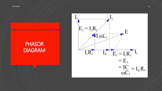
The Maxwell Bridge is an advanced form of the Wheatstone Bridge used to measure self-inductance in circuits through the null deflection method, comparing known and unknown inductance values. The bridge operates on principles of resonance and utilizes specific formulas for balanced conditions to determine unknown inductance and resistance. It has applications in various electronic and communication systems but also has limitations regarding high-quality factors and cost of components.


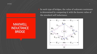
![For bridge to be balance,
Z1Z2 =Z3Z4
(R1+jwL1)x [R4 / (1+jwC4R4)] = R2R3
R1R4-R2R3 +jw(L1R4-R2R3C4R4) = 0
Equating real and imaginary parts we get,
R1 = R2R3 / R4
and L1 = R2R3C4
12/7/2020 14](https://image.slidesharecdn.com/maxwellbridge-201207042927/85/Maxwell-bridge-and-its-types-14-320.jpg)