Downloaded 1,142 times


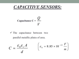
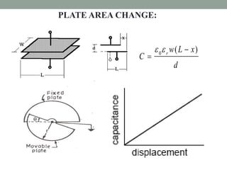


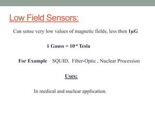


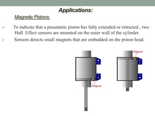
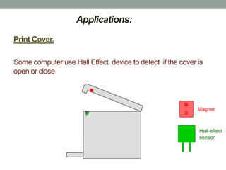

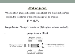


The document discusses different types of sensors including resistive, capacitive, piezoelectric, magnetic, and strain gauge sensors. It provides details on resistive sensors and their major types like potentiometers, strain gauges, thermistors, and light dependent resistors. The document also describes capacitive sensors, piezoelectric transducers, magnetic sensors like Hall effect sensors, and variable reluctance sensors. Finally, it covers strain gauge sensors, their working, and applications.