Downloaded 185 times

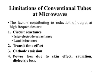
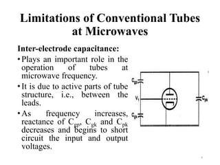
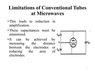
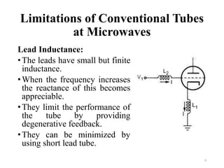
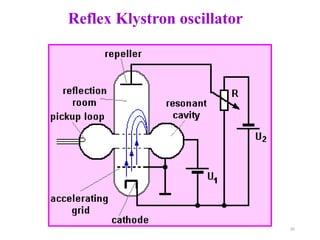
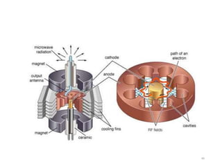
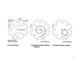

The document discusses various types of microwave tubes used to generate or amplify microwave signals. It describes the limitations of conventional tubes at microwave frequencies due to factors like inter-electrode capacitance, lead inductance, and transit time effect. It then discusses different microwave tube designs including klystrons, traveling wave tubes (TWTs), and magnetrons. Klystrons and TWTs are used for amplification and oscillation applications. Magnetrons are commonly used to generate microwaves in applications like radar and microwave ovens.