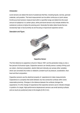
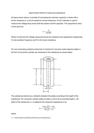
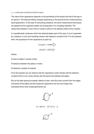
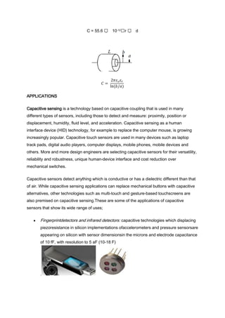
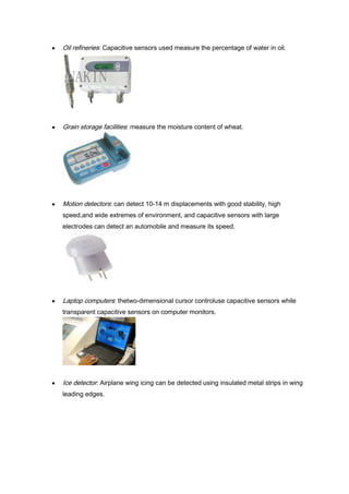
The document discusses liquid level capacitive sensors. It begins by describing how capacitive sensors can detect liquid levels by measuring changes in capacitance between sensor plates as the dielectric between them changes. It then provides figures to illustrate capacitive sensing concepts and equations to calculate capacitance based on plate area, distance, and dielectric. The document concludes by discussing applications of capacitive sensing including liquid level measurement, moisture detection, and touch interfaces.
Here in this presentation we will discussing about Inductive Transducer and its working principle, a brief classification of Inductive Transducer and derivation of transducer applications
A sensor is a device that detects and responds to some type of input from the physical environment.
The specific input could be light, heat, motion, moisture, pressure, or any one of a great number of other environmental phenomena.
The output is generally a signal that is converted to human-readable display at the sensor location or transmitted electronically over a network for reading or further processing.
In this slide there is all about the digital transducer and its types.Its is very helpful in making short notes of transducer. There is a simple description.
In this slide there is a description of liquid level transducer and its types. In this there is detail description of all its types with there diagrams. In this there is also a advantage and disadvantage of this transducer. Its application are also in these slides.
capacitive sensing (sometimes capacitance sensing) is a technology, based on capacitive coupling, that can detect and measure anything that is conductive or has a dielectric different from air. Many types of sensors use capacitive sensing, including sensors to detect and measure proximity, pressure, position and displacement, force, humidity, fluid level, and acceleration. Human interface devices based on capacitive sensing, such as trackpads, can replace the computer mouse. Digital audio players, mobile phones, and tablet computers use capacitive sensing touchscreens as input devices. Capacitive sensors can also replace mechanical buttons.
A capacitive touchscreen typically consists of a capacitive touch sensor along with at least two complementary metal-oxide-semiconductor (CMOS) integrated circuit (IC) chips, an application-specific integrated circuit (ASIC) controller and a digital signal processor (DSP). Capacitive sensing is commonly used for mobile multi-touch displays, popularized by Apple's iPhone in 2007.
apacitive sensors are constructed from many different media, such as copper, indium tin oxide (ITO) and printed ink. Copper capacitive sensors can be implemented on standard FR4 PCBs as well as on flexible material. ITO allows the capacitive sensor to be up to 90% transparent (for one layer solutions, such as touch phone screens). Size and spacing of the capacitive sensor are both very important to the sensor's performance. In addition to the size of the sensor, and its spacing relative to the ground plane, the type of ground plane used is very important. Since the parasitic capacitance of the sensor is related to the electric field's (e-field) path to ground, it is important to choose a ground plane that limits the concentration of e-field lines with no conductive object present.
Designing a capacitance sensing system requires first picking the type of sensing material (FR4, Flex, ITO, etc.). One also needs to understand the environment the device will operate in, such as the full operating temperature range, what radio frequencies are present and how the user will interact with the interface.
There are two types of capacitive sensing system: mutual capacitance,[5] where the object (finger, conductive stylus) alters the mutual coupling between row and column electrodes, which are scanned sequentially; and self- or absolute capacitance where the object (such as a finger) loads the sensor or increases the parasitic capacitance to ground. In both cases, the difference of a preceding absolute position from the present absolute position yields the relative motion of the object or finger during that time. The technologies are elaborated in the following section.
A proximity sensor is a sensor able to detect the presence of nearby objects without any physical contact. It detects An Object When The Object Approaches Within The Detection Range And Boundary Of The Sensor. Proximity Sensor Includes All The Sensor That Perform Non-Contact Detection In Comparison To Sensors Such As Limit Switch, That Detect The Object By Physically Contacting Them. It is a sensor able to detect the presence of nearby objects without any physical contact
This video demonstrates our Capacitive Pressure Sensor solution with USB output and/or Analog 0-5V output. It can also be converted into a wireless pressure sensor solution using our WX-100 wireless interface.
Modeling, Simulation and Design of a Circular Diaphragm Pressure Sensorkhalil fathi
This paper aim in design and analysis
of MEMS Pressure Sensor by using ANSYS
software. A diaphragm based MEMS sensor in
the range of 25MPa by measured center deflection of the circular pressure-sensitive and using the strain gauge for measurement.
Capacitive Sensing Design in Minutes - Capsense Capacitive SensorsDaniel Smith
Download the presentation here : www.cypress.com/training
Cypress Capacitive sensing solutions Brings in elegant, reliable, and easy-to-use Capacitive touch sensing functionality to your next design with the broadest touch-sensing portfolio, including the world's smallest packages and proximity sensors with a best-in-class detection range of up to 25 cm..
Tiny MEMS digital barometer for smartphones and wearables
The first barometric sensor from Infineon for the consumer market is targeting altitude, GPS, indoor and weather forecasting applications in portable devices. This MEMS sensor positions Infineon to compete with STMicroelectronics and Bosch Sensortec.
Infineon’s DPS310 pressure-sensing device is manufactured using a proprietary MEMS technology developed for and already sold for several years in the automotive market. The sensing element in the DPS310 is based on a flexible silicon membrane formed above an air cavity with a controlled gap and defined internal pressure. The membrane is very small compared to traditional silicon micro-machined membranes. Moreover, Infineon has developed a capacitive sensor to be more accurate and less sensitive to temperature change compared to piezoresistive solutions.
For the DPS310, Infineon has introduced two important innovations. The first is a two-die solution more scalable than the monolithic solution used for some automotive pressure sensors.
The second innovation is a plastic metallized lid to replace the classic metal lid. The device comes in a tiny 2x2.5x0.9mm HLGA molded package.
The report presents a detailed analysis of the sensor’s structure and cost. Comparison with the characteristics of the STMicroelectronics pressure sensor LPS22HB and the Bosch Sensortec BMP280 highlights differences in technical choices made by the companies.
More information on that report at http://www.i-micronews.com/reports.html
ECT SystemElectrical Capacitive tomography is used to find the p.docxjack60216
ECT System
Electrical Capacitive tomography is used to find the permittivity distribution of the material within an area; it is successfully employed to image the flow in pipes. An ECT sensor consists of pair of Electrodes surrounding the region where permittivity distribution needs to be found. A Schematic diagram of the capacitances measurement system is given below:
Figure 1 Complete ECT System [3]
The ECT system consists of system of measurement Electrodes that are known as sensors, these electrodes are excited by applying a potential on one electrode, whereas the rest of the electrode are grounded. The measurement system finds the capacitance between each excited electrode and the remaining electrode. It has already been outlined that there are N (N-1)/2, independent measurements possible with N electrodes [1]. Permittivity distribution is estimated from the measurements of the capacitance between the electrodes. It is therefore necessary to accurately model the influence of the permittivity distribution inside the ECT sensor on the measured capacitances to reach reliable estimations. The sensitivity matrix links the signal variation on one electrode to the permittivity variation in a given volume element inside the ECT sensing domain.
Figure 2 ECT Sensor with 04 Electrodes showing inter-electrode Capacitance
The Concept of sensitivity matrix and the approaches used to estimate it are of importance in finding the permittivity map or image of the sensing domain. The approached used to compute the sensitivity map would be discussed briefly in this report; however the major aim of this report is to discuss the design of the ECT sensor. The architecture of the ECT sensor is discussed along with the major components and purpose of the each of the each of the sensor. This report the simulation results to find the potential distribution within the sensing domain would be discussed along with the experimental results that are provided in the references and various approaches which are used to optimize different parameters are discussed.
ECT Sensor Architecture
Capacitance between the two electrodes depends on the effective area of the electrode and the permittivity of the medium in the sensing domain. In order to have larger capacitance it is desired that the area of the electrode be large, whereas if the area of electrode increases the spatial resolution decreases [2]. On the other hand area of the electrode cannot be decreased beyond a certain limit sine capacitance measured within the sensing domain has a variation of about 0.01pF and it poses some limitation on the measurement system since reducing the area of electrode decreases the signal hence it becomes difficult to measure the small capacitances. The figure below show the major components of the ECT Sensor
Figure 3 ECT Sensor System [2]
The ECT sensor has three different types of electrodes; main electrodes are used for capacitance measurement, axial electrodes and radial electro ...
Mechanical sensors and its working principles are discussed. The modern applications of the mechanical transducers or converters are also discussed. Motion, displacement, force, pressure, strain and many more concepts are discussed related mechanical sensors.
Magnetic Levitation through AC Excitationidescitation
A combination of AC excitation and series tuned
circuit can be used to levitate a ferromagnetic object by
magnetic levitation technique. The electromagnet forms the
inductive part of a resonating circuit. The circuit is tuned at a
frequency less than that of the exciting frequency. Therefore
when the distance between the object and the electromagnet
increases, there is fall in inductance of the lifting magnet,
the circuit approaches resonance and the coil current
increases. The magnetic force on the object increases and the
object moves to its desired position. Though the method is
simple, for slow change in coil current the levitated object
may move under influence of gravitational force and come to
rest position. Hence a new circuit with Z-source inverter with
shoot through is designed to bring the levitated object to its
desired position.
Epistemic Interaction - tuning interfaces to provide information for AI supportAlan Dix
Paper presented at SYNERGY workshop at AVI 2024, Genoa, Italy. 3rd June 2024
https://alandix.com/academic/papers/synergy2024-epistemic/
As machine learning integrates deeper into human-computer interactions, the concept of epistemic interaction emerges, aiming to refine these interactions to enhance system adaptability. This approach encourages minor, intentional adjustments in user behaviour to enrich the data available for system learning. This paper introduces epistemic interaction within the context of human-system communication, illustrating how deliberate interaction design can improve system understanding and adaptation. Through concrete examples, we demonstrate the potential of epistemic interaction to significantly advance human-computer interaction by leveraging intuitive human communication strategies to inform system design and functionality, offering a novel pathway for enriching user-system engagements.
UiPath Test Automation using UiPath Test Suite series, part 4DianaGray10
Welcome to UiPath Test Automation using UiPath Test Suite series part 4. In this session, we will cover Test Manager overview along with SAP heatmap.
The UiPath Test Manager overview with SAP heatmap webinar offers a concise yet comprehensive exploration of the role of a Test Manager within SAP environments, coupled with the utilization of heatmaps for effective testing strategies.
Participants will gain insights into the responsibilities, challenges, and best practices associated with test management in SAP projects. Additionally, the webinar delves into the significance of heatmaps as a visual aid for identifying testing priorities, areas of risk, and resource allocation within SAP landscapes. Through this session, attendees can expect to enhance their understanding of test management principles while learning practical approaches to optimize testing processes in SAP environments using heatmap visualization techniques
What will you get from this session?
1. Insights into SAP testing best practices
2. Heatmap utilization for testing
3. Optimization of testing processes
4. Demo
Topics covered:
Execution from the test manager
Orchestrator execution result
Defect reporting
SAP heatmap example with demo
Speaker:
Deepak Rai, Automation Practice Lead, Boundaryless Group and UiPath MVP
Slack (or Teams) Automation for Bonterra Impact Management (fka Social Soluti...Jeffrey Haguewood
Sidekick Solutions uses Bonterra Impact Management (fka Social Solutions Apricot) and automation solutions to integrate data for business workflows.
We believe integration and automation are essential to user experience and the promise of efficient work through technology. Automation is the critical ingredient to realizing that full vision. We develop integration products and services for Bonterra Case Management software to support the deployment of automations for a variety of use cases.
This video focuses on the notifications, alerts, and approval requests using Slack for Bonterra Impact Management. The solutions covered in this webinar can also be deployed for Microsoft Teams.
Interested in deploying notification automations for Bonterra Impact Management? Contact us at sales@sidekicksolutionsllc.com to discuss next steps.
Builder.ai Founder Sachin Dev Duggal's Strategic Approach to Create an Innova...Ramesh Iyer
In today's fast-changing business world, Companies that adapt and embrace new ideas often need help to keep up with the competition. However, fostering a culture of innovation takes much work. It takes vision, leadership and willingness to take risks in the right proportion. Sachin Dev Duggal, co-founder of Builder.ai, has perfected the art of this balance, creating a company culture where creativity and growth are nurtured at each stage.
LF Energy Webinar: Electrical Grid Modelling and Simulation Through PowSyBl -...DanBrown980551
Do you want to learn how to model and simulate an electrical network from scratch in under an hour?
Then welcome to this PowSyBl workshop, hosted by Rte, the French Transmission System Operator (TSO)!
During the webinar, you will discover the PowSyBl ecosystem as well as handle and study an electrical network through an interactive Python notebook.
PowSyBl is an open source project hosted by LF Energy, which offers a comprehensive set of features for electrical grid modelling and simulation. Among other advanced features, PowSyBl provides:
- A fully editable and extendable library for grid component modelling;
- Visualization tools to display your network;
- Grid simulation tools, such as power flows, security analyses (with or without remedial actions) and sensitivity analyses;
The framework is mostly written in Java, with a Python binding so that Python developers can access PowSyBl functionalities as well.
What you will learn during the webinar:
- For beginners: discover PowSyBl's functionalities through a quick general presentation and the notebook, without needing any expert coding skills;
- For advanced developers: master the skills to efficiently apply PowSyBl functionalities to your real-world scenarios.
Neuro-symbolic is not enough, we need neuro-*semantic*Frank van Harmelen
Neuro-symbolic (NeSy) AI is on the rise. However, simply machine learning on just any symbolic structure is not sufficient to really harvest the gains of NeSy. These will only be gained when the symbolic structures have an actual semantics. I give an operational definition of semantics as “predictable inference”.
All of this illustrated with link prediction over knowledge graphs, but the argument is general.
JMeter webinar - integration with InfluxDB and GrafanaRTTS
Watch this recorded webinar about real-time monitoring of application performance. See how to integrate Apache JMeter, the open-source leader in performance testing, with InfluxDB, the open-source time-series database, and Grafana, the open-source analytics and visualization application.
In this webinar, we will review the benefits of leveraging InfluxDB and Grafana when executing load tests and demonstrate how these tools are used to visualize performance metrics.
Length: 30 minutes
Session Overview
-------------------------------------------
During this webinar, we will cover the following topics while demonstrating the integrations of JMeter, InfluxDB and Grafana:
- What out-of-the-box solutions are available for real-time monitoring JMeter tests?
- What are the benefits of integrating InfluxDB and Grafana into the load testing stack?
- Which features are provided by Grafana?
- Demonstration of InfluxDB and Grafana using a practice web application
To view the webinar recording, go to:
https://www.rttsweb.com/jmeter-integration-webinar
Smart TV Buyer Insights Survey 2024 by 91mobiles.pdf91mobiles
91mobiles recently conducted a Smart TV Buyer Insights Survey in which we asked over 3,000 respondents about the TV they own, aspects they look at on a new TV, and their TV buying preferences.
Smart TV Buyer Insights Survey 2024 by 91mobiles.pdf
Capacitive sensor
1. FACULTY OF ELECTRICAL ENGINEERING UITM SHAH ALAM
CONTROL SYSTEM AND INSTRUMENTATION
( ESE439 )
“LIQUID LEVEL : CAPACITIVE”
PREPAREDBY :NOORSHAFIKA MOHAMAD NAZER ( 2009710725 )
NORAZLIN BT MOHD. RAZALI (2009297332)
NUR FATTAHIAH BT HASLAHUDDIN (2009)
GROUP : EE240 3A
DATE : 23 NOV 2011
2. Introduction
Level sensors can detect the level of substances that flow, including liquids, slurries, granular
materials, and powders. The level measurement can be either continuous or point values.
Continuous level sensors measure level within a specified range and determine the exact
amount of substance in a certain place, while point-level sensors only indicate whether the
substance is above or below the sensing point. Generally the latter detect levels that are
excessively high or low.Currently we are focusing on liquid level capacitive sensor.
Description and Figure
Capacitive Sensor
The first reference to capacitive is found in Nature 1907, but the peneration today is only a
few percent of all sensor types. Capacitive sensors can directly sense a variety of thing such
as motion, chemical composition, electric field and indirectly can senses other variables
which can converted into motion or dielectric constant such as pressure, accelaration, fluid
level and fluid composition.
Capacitive sensors use the electrical property of capacitance to make measurements.
Capacitance is a property that exists between any two conductive surfaces within some
reasonable proximity. Changes in the distance between the surfaces changes the
capacitance. It is this change of capacitance that capacitive sensors use to indicate changes
in position of a target. High-performance displacement sensors use small sensing surfaces
and as result are positioned close to the targets (0.25-2 mm).
3. Capacitance Liquid Level
They are built with conductive sensing electrodes in a dielectric, with excitation voltages on
the order of 5V and detection circuits which turn a capacitance variation into a voltage,
frequency, or pulse width variation. This technology is low cost and stability with simple
conditioning circuits. Often, the offset and gain adjustments needed the most sensor type are
not required.
Capacitance and Distance
Figure 1
Applying a voltage to conductive objects causes positive and negative chargesto collect on each
object.This creates an electric fieldin the space between the objects.
Noncontact capacitive sensors work by measuring changes in an electrical property called
capacitance. Capacitance describes how two conductive objects with a space between them
respond to a voltage difference applied to them. When a voltage is applied to the conductors,
an electric field is created between them causing positive and negative charges to collect on
each object (Fig. 1). If the polarity of the voltage is reversed, the charges will also reverse.
4. Figure 2
Applying an alternating voltage causes the charges to move back and forth between the objects,
creating an alternating current which is detected by the sensor.
Capacitive sensors use an alternating voltage which causes the charges to continually
reverse their positions. The moving of the charges creates an alternating electric current
which is detected by the sensor (Fig. 2). The amount of current flow is determined by the
capacitance, and the capacitance is determined by the area and proximity of the conductive
objects. Larger and closer objects cause greater current than smaller and more distant
objects. The capacitance is also affected by the type of nonconductive material in the gap
between the objects.
Figure 3
Capacitance is determined by Area, Distance, and Dielectric (the material between the conductors).
Capacitance increases when Area or Dielectric increase, and capacitance decreases when the
Distance increases.
Technically, the capacitance is directly proportional to the surface area of the objects and the
dielectric constant of the material between them, and inversely proportional to the distance
between them (Fig. 3).
In typical capacitive sensing applications, the probe or sensor is one of the conductive
objects and the target object is the other. The sizes of the sensor and the target are
assumed to be constant as is the material between them. Therefore, any change in
capacitance is a result of a change in the distance between the probe and the target. The
electronics are calibrated to generate specific voltage changes for corresponding changes in
capacitance. These voltages are scaled to represent specific changes in distance. The
amount of voltage change for a given amount of distance change is called the sensitivity. A
common sensitivity setting is 1.0V/100µm. That means that for every 100µm change in
distance, the output voltage changes exactly 1.0V. With this calibration, a +2V change in the
5. output means that the target has moved 200µm closer to the probe.
Electric Field
Figure 4
Capacitive sensor probe components
Figure 5
Cutaway view showing an unguarded sensing area electric field
Figure 6
Cutaway showing the guard field shaping the sensing area electric field
When a voltage is applied to a conductor, the electric field emanates from every surface. In a
capacitive sensor, the sensing voltage is applied to the Sensing Area of the probe (Figs. 4,
5).
6. For accurate measurements, the electric field from the sensing area needs to be contained
within the space between the probe and the target. If the electric field is allowed to spread to
other items or other areas on the target then a change in the position of the other item will be
measured as a change in the position of the target.
A technique called “guarding is used to prevent this from happening. To create a guard, the
back and sides of the sensing area are surrounded by another conductor that is kept at the
same voltage as the sensing area itself (Fig. 4, 6).
When the voltage is applied to the sensing area, a separate circuit applies the exact same
voltage to the guard. Because there is no difference in voltage between the sensing area and
the guard, there is no electric field between them. Any other conductors beside or behind the
probe form an electric field with the guard instead of the sensing area. Only the unguarded
front of the sensing area is allowed to form an electric field with the target.
The target size is a primary consideration when selecting a probe for a specific application.
When the sensing electric field is focused by guarding, it creates a slightly conical field that is
a projection of the sensing area. The minimum target diameter for standard calibration is
30% of the diameter of the sensing area. The further the probe is from the target, the larger
the minimum target size.
In general, the maximum gap at which a probe is useful is approximately 40% of the
sensor diameter. Standard calibrations usually keep the gap considerably less than
that.
The range in which a probe is useful is a function of the size of the sensing area. The greater
the area, the larger the range. The driver electronics are designed for a certain amount of
capacitance at the probe. Therefore, a smaller probe must be considerably closer to the
target to achieve the desired amount of capacitance. The electronics are adjustable during
calibration but there is a limit to the range of adjustment.In general, the maximum gap at
which a probe is useful is approximately 40% of the sensing area diameter. Standard
calibrations usually keep the gap considerably less than that.
Using multiple probes on the same target requires that the excitation voltages be
synchronized. This is accomplished by configuring one driver as a master and others
as slaves. Frequently, a target is measured simultaneously by multiple probes. Because the
7. system measures a changing electric field, the excitation voltage for each probe must be
synchronized or the probes would interfere with each other. If they were not synchronized,
one probe would be trying to increase the electric field while another was trying to decrease it
thereby giving a false reading.
Driver electronics can be configured as masters or slaves. The master sets the
synchronization for the slaves in multiple channel systems.
Capacitive sensors measure all conductors: brass, steel, aluminium, or even salt-water, as
the same. The sensing electric field is seeking a conductive surface. Provided that the target
is a conductor, capacitive sensors are not affected by the specific target material. Because
the sensing electric field stops at the surface of the conductor, target thickness does not
affect the measurement. .
Measuring Non-Conductors
Figure 7
Non-conductors can be measured by passing the electric field through them to a stationary
conductive target behind.
Figure 8
Without a conductive target behind, a fringe field can form through a nearby non-conductor
allowing the non-conductor to be sensed
8. Capacitive sensors are most often used to measure the change in position of a conductive
target. But capacitive sensors can be very effective in measuring presence, density,
thickness, and location of non-conductors as well. Non-conductive materials like plastic have
a different dielectric constant than air. The dielectric constant determines how a non-
conductive material affects capacitance between two conductors. When a non-conductor is
inserted between the probe and a stationary reference target, the sensing field passes
through the material to the grounded target (Fig. 7). The presence of the non-conductive
material changes the dielectric and therefore changes the capacitance. The capacitance will
change in relationship to the thickness or density of the material.
It is not always feasible to have a reference target in front of the probe. Measurements may
still be possible by a technique called fringing. If there is no conductive reference directly in
front of the probe, the sensing electric field will wrap back to the body of the probe itself. This
is called a fringe field. If a non-conductive material is brought in proximity to the probe, its
dielectric will change the fringe field; this can be used to sense the non-conductive material.
The sensitivity of the sensor to the non-conductive target is directly proportional to the
dielectric constant of the material.
Compared to other noncontact sensing technologies such as optical, laser, eddy-current, and
inductive, high-performance capacitive sensors have some distinct advantages.
Higher resolutions including subnanometer resolutions
Not sensitive to material changes: Capacitive sensors respond equally to all
conductors
Less expensive and much smaller than laser interferometers.
Meanwhile, this capacitive technology is sensitive to humidity and needs unstable, high
impedance circuits. In fact, as the dielectric constant of humid is only a few ppm higher that
dry air, humidity itself is not a problem. Very high impedance circuit needed. The capacitive
sensor are rugged as any other sensor type. Its can not tolerate immersion or condensing
humidity, but a few circuits can.
Capacitive sensors are not good choice in these conditions:
Dirty or wet environment (eddy-current sensors are ideal)
Large gap between sensor and target is required (optical and laser are better)
9. The design usually consider following steps:
Design eletcrode plates to measure the desired variable. Maximize capacitance with
large area, close spaced plates.
Surround this sensor with appropriate guard or shield electrodes to handle stray
capacitance and crosstalk from other circuits.
Calculate sensor capacitance, stray capacitance and output signal swing.
Specify tranfer function like Eo = C (area-linear), Eo = 1/C (spacing-linear) . Use two
balanced capacitors for high capacitors for high accuracy with transfer function like
C1/C2 or (C1-C2)/(C1+C2) .
Choose an excitation frequency high enough for low noise.As excitation frequency
increases, external and circuit generated noise decreases.
Design circuit to meet accuracy specifications and provide immunity to environment
challenges.
10. CIRCUITRY AND EQUATION
Devices that have an output in the form of a change in capacitance include a capacitive level
gauge, capacitive displacement sensor, capacitive moisture meter and capacitive
hygrometer. Capacitance is measured in unit of Farad (F). Like inductance, capacitance can
be measured accurately by an AC bridge circuit and various type of Capacitance Bridge is
available commercially.
As an example, dry leather has a loss tangent of 0.045, but with a relative humidity of 15%
the loss tangent increases to 1.4--possibly a good hygrometer. Aviation gas at 100 octane
exhibits a loss tangent at 1 kHz of 0.0001, but at 91 octane loss tangent increases to 0.0004.
Water has a high K (80) and a loss tangent which peaks at low frequencies and again at
1010 Hz. With this high dielectric activity, the loss tangent or the dielectric constant of water
can be used to detect the moisture content of materials.
Another characteristic of capacitor dielectrics which may have some use in detecting material
properties is dielectric absorption. It is measured by charging a capacitor, discharging for 10
s, and measuring the charge which reappears after 15 min. A relatively low-quality dielectric
like metalized paper has a dielectric absorption of 10%.
Approximate method of measuring inductance
11. Approximate method of measuring capacitance
As figure shown above, it consists of connecting the unknown capacitor in series with a
known resistance in a circuit excited at a known frequency. An AC voltmeter is used to
measure the voltage drop across both the resistor and the capacitor. The capacitance value
is then given by:
Where VrandVcare the voltage measured across the resistance and capacitance respectively,
f is the excitation frequency and R is the known resistance.
For non-conducting substance (less than 0.1µmho/cm3), two bare metal capacitor plates in
the form of concentric cylinder are immersed in the substances as shown below.
The substances behave as a dielectric between the plates according to the depth of the
substances. For concentric cylinder plates of radius a and b (b>a) and total height L, the
depth of the substances, h, is related to the measured capacitance C by:
where
12. The value of the capacitance depends on the permittivity of the liquids and that of the gas or
air above it. The total permittivity changes depending on the liquid level (for non0conducting
liquid application). In the case of conducting substance, the same measurement techniques
are applied but the capacitors plates are encapsulate in an insulating materials. The
relationship between C and h has to modify to allow for the dielectric effect of the insulator.
In a parallel plate condenser which has identical plates each of the area, A (cm3) separated
by a distance, d (cm) and insulating medium with dielectric constant K (K=1 for air) between
them, the expression for the capacitance is given by:
or
Where;
A=area of plates in square inches
D=distance between the plates in inches
K=dielectric constant of material
From the equation we can observe that the capacitance varies directly with the dielectric
constant which is turn varies directly with the liquid level between the plates.
But as the plate spacing increases relative to area, more flux lines connect from the edges
and backs of the plates and the measured capacitance can be much larger than
calculated.Some other simple geometries are
C = 35.4 10-12r d
13. C = 55.6 10-12r d
APPLICATIONS
Capacitive sensing is a technology based on capacitive coupling that is used in many
different types of sensors, including those to detect and measure: proximity, position or
displacement, humidity, fluid level, and acceleration. Capacitive sensing as a human
interface device (HID) technology, for example to replace the computer mouse, is growing
increasingly popular. Capacitive touch sensors are used in many devices such as laptop
track pads, digital audio players, computer displays, mobile phones, mobile devices and
others. More and more design engineers are selecting capacitive sensors for their versatility,
reliability and robustness, unique human-device interface and cost reduction over
mechanical switches.
Capacitive sensors detect anything which is conductive or has a dielectric different than that
of air. While capacitive sensing applications can replace mechanical buttons with capacitive
alternatives, other technologies such as multi-touch and gesture-based touchscreens are
also premised on capacitive sensing.These are some of the applications of capacitive
sensors that show its wide range of uses;
Fingerprintdetectors and infrared detectors: capacitive technologies which displacing
piezoresistance in silicon implementations ofaccelerometers and pressure sensorsare
appearing on silicon with sensor dimensionsin the microns and electrode capacitance
of 10 fF, with resolution to 5 aF (10-18 F)
.
14. Oil refineries: Capacitive sensors used measure the percentage of water in oil.
Grain storage facilities: measure the moisture content of wheat.
Motion detectors: can detect 10-14 m displacements with good stability, high
speed,and wide extremes of environment, and capacitive sensors with large
electrodes can detect an automobile and measure its speed.
Laptop computers: thetwo-dimensional cursor controluse capacitive sensors while
transparent capacitive sensors on computer monitors.
Ice detector: Airplane wing icing can be detected using insulated metal strips in wing
leading edges.
15. Thickness measurement: Two plates in contact with an insulator will measure
theinsulator thickness if its dielectric constant is known, or the dielectric constant if
thethickness is known.
wafer thickness sensor 1
Lamp dimmer switch: The common metal-plate soft-touch lamp dimmer uses 60Hz
excitation and senses the capacitance to a human body.
16. Limit switch: detect the proximity of a metal machine componentas an increase in
capacitance, or the proximity of a plastic component by virtue of its increased
dielectric constant over air.
Liquid level: Capacitive liquid level detectors sense the liquid level in a reservoirby
measuring changes in capacitance between conducting plates which areimmersed in
the liquid, or applied to the outside of a non-conducting tank.