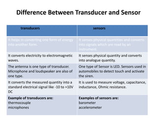
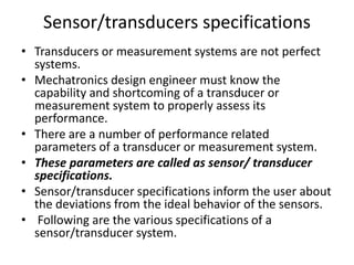
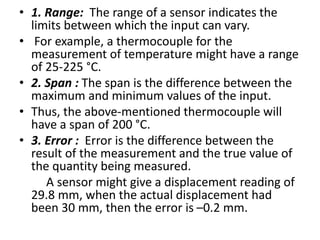
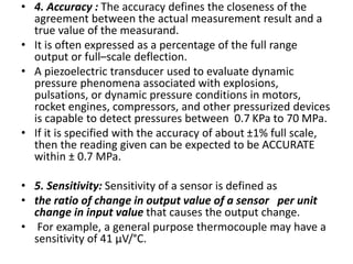
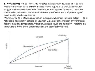
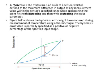
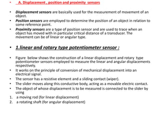
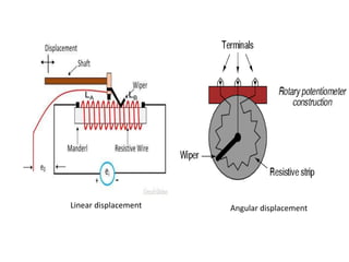
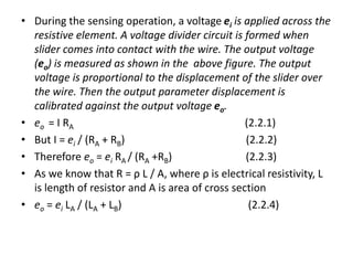
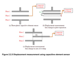
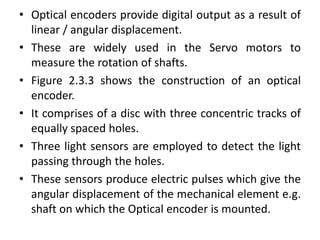
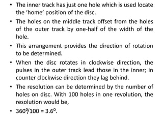
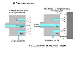
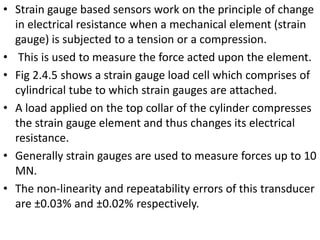
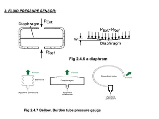
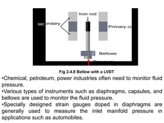
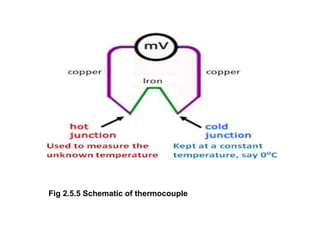
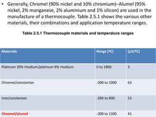
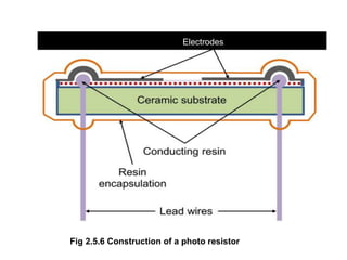
SlideShare a Scribd company logo
Sensors and transducers
•Measurement is an important subsystem of a Mechatronics
system.
•Its main function is to collect the information on system
status and to feed it to the micro-processor(s) for controlling
the whole system.
• Measurement system comprises of sensors, transducers and
signal processing devices.
•Today a wide variety of these elements and devices are
available in the market.
•For a Mechatronics system designer, it is quite difficult to
choose suitable sensors/transducers for the desired
application(s).
•It is therefore essential to learn the working principle of
commonly used sensors/transducers.
•A detailed consideration of the full range of measurement
technologies is, however, out of the scope of this course.
• Sensors in manufacturing are basically employed
a). to automatically carry out the production
operations as well as
b). to automatically carry out the process monitoring
activities.
• Sensor technology has the following important
advantages in transforming a conventional
manufacturing unit into a modern one.
• 1. Sensors alarm the system operators about the failure
of any of the sub units of manufacturing system. It
helps operators to reduce the downtime of complete
manufacturing system by carrying out the preventative
measures.
• 2. Reduces requirement of skilled and experienced
labors.
• 3. Ultra-precision in product quality can be achieved.
Sensor
• It is defined as an element which produces signal
relating to the quantity being measured .
• According to the Instrument Society of
America(ISA), sensor can be defined as “A device
which provides a usable output in response to a
specified measurand.”
• Here, the output is usually an ‘electrical quantity’
and measurand is a ‘physical quantity, property
or condition which is to be measured’.
• Thus in the case of, say, a variable inductance
displacement element, the quantity being
measured is displacement and the sensor
transforms an input of displacement into a
change in inductance(emf).
Transducer
• It is defined as an element when subjected to some
physical change experiences a related change or an
element which converts a specified measurand into a
usable output by using a transduction principle,
(conversion of one form of energy in to another form).
• It can also be defined as a device that converts a signal
from one form of energy to another form.
• A wire of Constantan alloy (copper-nickel 55-45% alloy)
can be called as a sensor because variation in
mechanical deformation (tension or compression) can
be sensed as change in electric resistance.
• This wire becomes a transducer with appropriate
electrodes and input-output mechanism attached to it.
Thus we can say that ‘sensors are transducers’.
Difference Between Transducer and Sensor
transducers sensors
It helps in converting one form of energy
into another form.
It senses physical quantities and converts
into signals which are read by an
instrument.
It converts electricity to electromagnetic
waves.
It senses physical quantity and converts
into analogue quantity.
The antenna is one type of transducer.
Microphone and loudspeaker are also of
one type.
One type of Sensor is LED. Sensors used in
automobiles to detect touch and activate
the siren.
It converts the measured quantity into a
standard electrical signal like -10 to +10V
DC
It is used to measure voltage, capacitance,
inductance, Ohmic resistance.
Example of transducers are:
thermocouple
microphones
Examples of sensors are:
barometer
accelerometer
Sensor/transducers specifications
• Transducers or measurement systems are not perfect
systems.
• Mechatronics design engineer must know the
capability and shortcoming of a transducer or
measurement system to properly assess its
performance.
• There are a number of performance related
parameters of a transducer or measurement system.
• These parameters are called as sensor/ transducer
specifications.
• Sensor/transducer specifications inform the user about
the deviations from the ideal behavior of the sensors.
• Following are the various specifications of a
sensor/transducer system.
• 1. Range: The range of a sensor indicates the
limits between which the input can vary.
• For example, a thermocouple for the
measurement of temperature might have a range
of 25-225 °C.
• 2. Span : The span is the difference between the
maximum and minimum values of the input.
• Thus, the above-mentioned thermocouple will
have a span of 200 °C.
• 3. Error : Error is the difference between the
result of the measurement and the true value of
the quantity being measured.
A sensor might give a displacement reading of
29.8 mm, when the actual displacement had
been 30 mm, then the error is –0.2 mm.
• 4. Accuracy : The accuracy defines the closeness of the
agreement between the actual measurement result and a
true value of the measurand.
• It is often expressed as a percentage of the full range
output or full–scale deflection.
• A piezoelectric transducer used to evaluate dynamic
pressure phenomena associated with explosions,
pulsations, or dynamic pressure conditions in motors,
rocket engines, compressors, and other pressurized devices
is capable to detect pressures between 0.7 KPa to 70 MPa.
• If it is specified with the accuracy of about ±1% full scale,
then the reading given can be expected to be ACCURATE
within ± 0.7 MPa.
• 5. Sensitivity: Sensitivity of a sensor is defined as
• the ratio of change in output value of a sensor per unit
change in input value that causes the output change.
• For example, a general purpose thermocouple may have a
sensitivity of 41 µV/°C.
6. Nonlinearity : The nonlinearity indicates the maximum deviation of the actual
measured curve of a sensor from the ideal curve. Figure 2.1.1 shows a somewhat
exaggerated relationship between the ideal, or least squares fit line and the actual
measured or calibration line. Linearity is often specified in terms of percentage of
nonlinearity, which is defined as:
•Nonlinearity (%) = Maximum deviation in output ⁄ Maximum full scale output (2.1.1)
•The static nonlinearity defined by Equation 2.1.1 is dependent upon environmental
factors, including temperature, vibration, acoustic level, and humidity. Therefore it is
important to know under what conditions the specification is valid
• 7. Hysteresis : The hysteresis is an error of a sensor, which is
defined as the maximum difference in output at any measurement
value within the sensor’s specified range when approaching the
point first with increasing and then with decreasing the input
parameter.
• Figure below shows the hysteresis error might have occurred during
measurement of temperature using a thermocouple. The hysteresis
error value is normally specified as a positive or negative
percentage of the specified input range.
• 8. Resolution :
• Resolution is the smallest detectable incremental
output signal.
• Resolution can be expressed either as a proportion of
the full-scale reading or in absolute terms.
• For example, if a LVDT sensor measures a smallest
displacement of 1 mm , it’s resolution will be 1 mm. Or
if it can measure a displacement of .5 mm , that means
higher resolution.
• 9. Stability :
• Stability is the ability of a sensor device to give same
output when used to measure a constant input over a
period of time. The term ‘drift’ is used to indicate the
change in output that occurs over a period of time. It is
expressed as the percentage of full range output.
• 10.Dead band & Dead time:
• Dead band The dead band or dead space of a transducer is
the range of input values for which there is no output.
• Dead time The dead time of a sensor device is the time
duration from the application of an input until the output
begins to respond or change.
• 11.Repeatability :
• It specifies the ability of a sensor to give same output for
repeated applications of same input value. It is usually
expressed as a percentage of the full range output:
• Repeatability = (maximum – minimum values given) X 100 ⁄
full range (2.1.2)
• 12.Response time
• Response time describes
• the speed of change in the output on a step-
wise change of the measurand.
• Classification of sensors :
• Sensors can be classified into various groups
according to the factors such as measurand,
application fields, conversion principle, energy
domain of the measurand and
thermodynamic considerations.
• Detailed classification of sensors in view of their applications in
manufacturing is as follows.
• A. Displacement, position and proximity sensors
• Potentiometer
• Strain-gauged element
• Capacitive element
• Differential transformers
• Eddy current proximity sensors
• Inductive proximity switch
• Optical encoders
• Pneumatic sensors
• Proximity switches (magnetic)
• Hall effect sensors
• B. Velocity and motion
• Incremental encoder
• Tachogenerator
• Pyroelectric sensors
• C. Force
• Strain gauge load cell
• D. Fluid pressure
• Diaphragm pressure gauge
• Capsules, bellows, pressure tubes
• Piezoelectric sensors
• Tactile sensor
• E. Liquid flow
• Orifice plate
• Turbine meter
• F. Liquid level
• Floats
• Differential pressure
• G. Temperature
• Bimetallic strips
• Resistance temperature detectors (RTD)
• Thermistors
• Thermo-diodes and transistors
• Thermocouples
• Light sensors
• Photo diodes
• Photo resistors
• Photo transistor
• A. Displacement , position and proximity sensors
• Displacement sensors are basically used for the measurement of movement of an
object.
• Position sensors are employed to determine the position of an object in relation to
some reference point.
• Proximity sensors are a type of position sensor and are used to trace when an
object has moved with in particular critical distance of a transducer. The
movement can be of linear or angular type.
• 1.linear and rotary type potentiometer sensor :
• Figure below shows the construction of a linear displacement and rotary type
potentiometer sensors employed to measure the linear and angular displacements
respectively.
• It works on the principle of conversion of mechanical displacement into an
electrical signal.
• The sensor has a resistive element and a sliding contact (wiper).
• The slider moves along this conductive body, acting as a movable electric contact.
• The object of whose displacement is to be measured is connected to the slider by
using
1. a moving rod (for linear displacement)
2. a rotating shaft (for angular displacement)
Linear displacement Angular displacement
LA LB
• During the sensing operation, a voltage ei is applied across the
resistive element. A voltage divider circuit is formed when
slider comes into contact with the wire. The output voltage
(eo) is measured as shown in the above figure. The output
voltage is proportional to the displacement of the slider over
the wire. Then the output parameter displacement is
calibrated against the output voltage eo.
• eo = I RA (2.2.1)
• But I = ei / (RA + RB) (2.2.2)
• Therefore eo = ei RA / (RA +RB) (2.2.3)
• As we know that R = ρ L / A, where ρ is electrical resistivity, L
is length of resistor and A is area of cross section
• eo = ei LA / (LA + LB) (2.2.4)
• Applications of potentiometer:
• These sensors are primarily used in the control systems with a
feedback loop to ensure that the moving member or
component reaches its commanded position.
• These are typically used on machine-tool controls, elevators,
liquid-level assemblies, forklift trucks, automobile throttle
controls.
• In manufacturing, these are used in control of injection
molding machines, woodworking machinery, printing,
spraying, robotics, etc.
• 2. Strain Gauges :
• The strain in an element is a ratio of change in length in the
direction of applied load to the original length of an element.
The strain(change in length) changes the resistance R of the
element. Therefore, we can say,
• ΔR/R α ε;
• ΔR/R = G ε (2.2.5)
• where G is the constant of proportionality and is called as
gauge factor.
• In general, the value of G is considered in between 2 to 4 and
the resistances are taken of the order of 100 Ω.
Figure 2.2.3 A resistance strain gauge
•Resistance strain gauge follows the principle of change in
resistance is proportional to change in length ,as per the
equation 2.2.5.
•It comprises of a pattern of resistive foil/ wire arranged as
shown in Figure 2.2.3.
•These foils are made of Constantan alloy (copper-nickel 55-
45% alloy) and are bonded to a backing material plastic
(polyimide), epoxy or glass fiber reinforced epoxy.
•The strain gauges are secured to the work piece by using
epoxy or Cyanoacrylate cement Eastman 910 SL.
•As the work piece undergoes change in its shape due to
external loading, the resistance of strain gauge element
changes in proportion.
•This change in resistance can be detected by a using a
Wheat stone's resistance bridge as shown in Figure 2.2.4.
Figure 2.2.4 Wheat stone's bridge
•In the balanced bridge we can have a relation,
R2/ R1 = Rx / R3 , R1, R2 and R3 are chosen such that the bridge is
balanced. (2.2.6)
where Rx is resistance of strain gauge element, R2 is balancing/adjustable
resistor R1 and R3 are known constant value resistors.
•The measured deformation / displacement by the stain gauge is calibrated
against change in resistance of adjustable resistor R2 which makes the voltage
across nodes A and B equal to zero
Vs Supply voltage
Vo Output voltage
• Applications of strain gauges :
• Strain gauges are widely used in experimental stress
analysis and diagnosis on machines and failure
analysis.
• They are basically used for multi-axial stress fatigue
testing, residual stress and vibration measurement,
torque measurement, bending and deflection
measurement, compression and tension
measurement and strain measurement.
• Strain gauges are primarily used as sensors for
machine tools and safety in automotives. In
particular, they are employed for force measurement
in machine tools, hydraulic or pneumatic press and
as impact sensors in aerospace vehicles
• 3. Capacitive element based sensor
• Capacitive sensor is of non-contact type sensor and is
primarily used to measure the linear displacements from
few millimeters to hundreds of millimeters.
• It comprises of three plates, with the upper pair forming
one capacitor and the lower pair another. The linear
displacement might take in two forms:
• a. one of the plates is moved by the displacement so that
the plate separation changes
• b. area of overlap changes due to the displacement.
• Figure 2.2.5 shows the schematic of three-plate capacitive
element sensor and displacement measurement of a
mechanical element connected to the plate 2.
Figure 2.2.5 Displacement measurement using capacitive element sensor
• The capacitance C of a parallel plate capacitor is given by,
• C = εr εo A / d (2.2.7)
• where εr is the relative permittivity of the dielectric between the
plates, εo permittivity of free space, A -area of overlap between two
plates and d- the plate separation.
• As the central plate moves near to top plate or bottom one due to
the movement of the element/work piece of which displacement is
to be measured, separation in between the plate changes. This can
be given as,
• C1 = (εr εo A) / (d + x) (2.2.8)
• C2 = (εr εo A) / (d – x) (2.2.9)
• When C1 and C2 are connected to a Wheat stone’s bridge, then the
resulting out-of-balance voltage would be in proportional to
displacement x.
• Capacitive elements can also be used as proximity sensor. The approach
of the object towards or away from the sensor plate is used for an
induction of change in plate separation. This changes the capacitance
which is used to detect the object.
• Applications of capacitive element sensors :
• • Feed hopper level monitoring
• • Small vessel level control
• • Grease level monitoring
• • Level control of liquids
• • Metrology applications
• i). to measure shape errors in the part being produced
• ii). to analyze and optimize the rotation of spindles in various machine
tools such as surface grinders, lathes, milling machines, and air bearing
spindles by measuring errors in the machine tools themselves
• • Assembly line testing
• i). to test assembled parts for uniformity, thickness or other design
features
• Ii). to detect the presence or absence of a certain component, such as
glue etc.
Primary coil Secondary coil
Figure 2.2.6 Construction of a LVDT sensor
4. Linear variable differential transformer (LVDT):
Working principle of LVDT
• Linear variable differential transformer (LVDT) is a primary
transducer used for measurement of linear displacement
with an input range of about ± 2 to ± 400 mm in general.
• It has non-linearity error ± 0.25% of full range.
• Figure 2.2.6 shows the construction of a LVDT sensor.
• It has three coils symmetrically spaced along an insulated
tube.
• The central coil is primary coil and the other two are
secondary coils.
• Secondary coils are connected in series in such a way that
their outputs oppose each other.
• A magnetic core attached to the element of which
displacement is to be monitored is placed inside the
insulated tube.
• Due to an alternating voltage input to the primary coil,
alternating electro-magnetic forces (emf) are generated in
secondary coils.
• When the magnetic core is centrally placed with its half
portion in each of the secondary coil regions then the
resultant voltage is zero.
• If the core is displaced from the central position as shown
in Figure 2.2.7, say, more in secondary coil 1 than in coil 2,
then more emf is generated in one of the coils i.e. coil 1
than the other, and there is a resultant voltage from the
coils.
• If the magnetic core is further displaced, then the value of
resultant voltage increases in proportion with the
displacement.
• With the help of signal processing devices such as low pass
filters and demodulators, precise displacement can be
measured by using LVDT sensors.
• LVDT exhibits good repeatability and reproducibility.
• It is generally used as an absolute position sensor.
• Since there is no contact or sliding between the constituent
elements of the sensor, it is highly reliable.
• These sensors are completely sealed and are widely used in
Servomechanisms, automated measurement in machine
tools.
• A rotary variable differential transformer (RVDT) can be
used for the measurement of rotation. Students are
suggested to prepare a report on principle of working and
construction of RVDT sensor.
•Applications of LVDT sensors :
• Measurement of spool position in a wide range of servo
valve applications
• To provide displacement feedback for hydraulic
cylinders
• To control weight and thickness of medicinal products
viz. tablets or pills
• For automatic inspection of final dimensions of
products being packed for dispatch
• To measure distance between the approaching metals
during Friction welding process
• To continuously monitor fluid level as part of leak
detection system
• To detect the number of currency bills dispensed by
an ATM :
• In an ATM, Macro Sensors' PR 750 Series of Linear
Position Sensors are used to measure the separation
of a pair of rollers, whereby bills (currency) passing
between the rollers displace the LVDT core.
• As the bills pass between the rollers, the LVDT output
changes according to their thickness.
• As a typical bill measures 0.0003" (0.0075mm) thick,
the LVDT will detect any derivation should two or
more bills get stuck together.
5. OPTICAL ENCODERS:
Fig. 2.3.3, optical encoder
Photo diode
• Optical encoders provide digital output as a result of
linear / angular displacement.
• These are widely used in the Servo motors to
measure the rotation of shafts.
• Figure 2.3.3 shows the construction of an optical
encoder.
• It comprises of a disc with three concentric tracks of
equally spaced holes.
• Three light sensors are employed to detect the light
passing through the holes.
• These sensors produce electric pulses which give the
angular displacement of the mechanical element e.g.
shaft on which the Optical encoder is mounted.
• The inner track has just one hole which is used locate
the ‘home’ position of the disc.
• The holes on the middle track offset from the holes
of the outer track by one-half of the width of the
hole.
• This arrangement provides the direction of rotation
to be determined.
• When the disc rotates in clockwise direction, the
pulses in the outer track lead those in the inner; in
counter clockwise direction they lag behind.
• The resolution can be determined by the number of
holes on disc. With 100 holes in one revolution, the
resolution would be,
• 360⁰/100 = 3.6⁰.
6. Pneumatic sensors:
Fig. 2.3.4 working of pneumatic sensors
• Pneumatic sensors are used to measure the displacement as well as
to sense the proximity of an object close to it.
• The displacement and proximity are transformed into change in air
pressure.
• Figure 2.3.4 shows a schematic of construction and working of such a
sensor.
• It comprises of three ports.
• Low pressure air is allowed to escape through port A.
• In the absence of any obstacle / object, this low pressure air escapes
and in doing so, reduces the pressure in the port B.
• However when an object obstructs the low pressure air (Port A),
there is rise in pressure in output port B.
• This rise in pressure is calibrated to measure the displacement or to
trigger a switch.
• These sensors are used in robotics, pneumatics and for tooling in CNC
machine tools.
7. Contact type proximity switches:
Fig 2.3.5 Configurations of contact proximity switches used in manufacturing automation
a. Lever operated b. Roller operated c. Cam operated
• Magnet based Reed switches are used as proximity
switches. When a magnet attached to an object is
brought close to the switch, the magnetic reeds
attract to each other and close the switch contacts. A
schematic is shown in Fig 2.3.6.
8. Magnetic reed switch:
Fig 2.3.6 Magnetic Reed Switch
Magnet connected to an object
9. LED based proximity sensor:
Photo emitting devices such as Light emitting diodes (LEDs) and photosensitive
devices such as photo diodes and photo transistors are used in combination to
work as proximity sensing devices. Figure 2.3.7 shows arrangement of LEDand
photo diode to detect the objects breaking the beam and reflecting light.
Photo diode
D C SUPPLY
10. Hall effect sensor:
Figure 2.3.8 principle of working of Hall effect sensor
• Fig 2.3.8 shows the principle of working of Hall effect
sensor.
• Hall effect sensors work on the principle that when a beam
of charge particles (electric charge, current) passes through
a magnetic field, forces act on the particles and the current
beam is deflected from its straight line path.
• Thus one side of the disc will become negatively charged
and the other side will be of positive charge.
• This charge separation generates a potential difference
which is the measure of distance of magnetic field from the
disc carrying current.
• The typical application of Hall effect sensor is the
measurement of fluid level / fuel level in a fuel tank.
• The container comprises of a float with a permanent
magnet attached at its top.
• An electric circuit with a current carrying disc is mounted in
the casing.
• When the fluid level increases, the magnet will come close
to the disc and a potential difference generates.
• This voltage triggers a switch to stop the fluid to come
inside the container.
• These sensors are used for the measurement of displacement
and the detection of position of an object.
• Hall effect sensors need necessary signal conditioning
circuitry.
• Their non-contact nature of operation, good immunity to
environment contaminants and ability to sustain in severe
conditions make them quite popular in industrial
automation.
2. Velocity, motion, force and
pressure sensors:
Figure 2.4.1 Principle of working of Techogenerator
• The variable reluctance sensor consists of a wire wrapped
around a permanent magnet. When the ferromagnetic
material such as a flywheel tooth passes the sensor the
magnetic field is disrupted. Due to this, an AC voltage is
generated, the amplitude and frequency of which depends
on the speed of the flywheel.
• Tacho generator works on the principle of variable
reluctance.
• It consists of an assembly of a toothed wheel and a
magnetic circuit as shown in figure 2.4.1.
• Toothed wheel is mounted on the shaft or the element of
which angular motion is to be measured.
• Magnetic circuit comprises of a coil wound on a
ferromagnetic material core.
• As the wheel rotates, the air gap between wheel
tooth and magnetic core changes which results in
cyclic change in flux linked with the coil causing the
generation of the voltage in the coil.
• The alternating emf generated is the measure of
angular motion.
Carbon brushes
Slip rings
Figure 2.4.2 Construction and working of AC generator
1. tachogenerator:
• An alternating current (AC) generator can also be used
as a velocity measuring device, a tachogenerator.
• It comprises of rotor coil which rotates with the shaft.
• Figure 2.4.2 shows the schematic of AC generator. The
rotor rotates in the magnetic field produced by a
stationary permanent magnet or electromagnet.
• During this process, an alternating emf is produced in
the rotating coil which is the measure of the angular
velocity of the rotor.
• In general, these sensors exhibit nonlinearity error of
about ± 0.15% and are employed for the rotations up to
about 10000 rev/min.
2. Strain gauge as a force
sensor:
Fig 2.4.5 Strain gauge based Load cell
• Strain gauge based sensors work on the principle of change
in electrical resistance when a mechanical element (strain
gauge) is subjected to a tension or a compression.
• This is used to measure the force acted upon the element.
• Fig 2.4.5 shows a strain gauge load cell which comprises of
cylindrical tube to which strain gauges are attached.
• A load applied on the top collar of the cylinder compresses
the strain gauge element and thus changes its electrical
resistance.
• Generally strain gauges are used to measure forces up to 10
MN.
• The non-linearity and repeatability errors of this transducer
are ±0.03% and ±0.02% respectively.
3. FLUID PRESSURE SENSOR:
Fig 2.4.7 Bellow, Burdon tube pressure gauge
Fig 2.4.6 a diaphram
sec
pressure
Fig 2.4.8 Bellow with a LVDT
•Chemical, petroleum, power industries often need to monitor fluid
pressure.
•Various types of instruments such as diaphragms, capsules, and
bellows are used to monitor the fluid pressure.
•Specially designed strain gauges doped in diaphragms are
generally used to measure the inlet manifold pressure in
applications such as automobiles.
•
• A typical arrangement of strain gauges on a diaphragm is shown in
figure 2.4.6, Application of pressurized fluid displaces the
diaphragm.
• This displacement is measured by the stain gauges in terms of radial
and/or lateral strains.
• These strain gauges are connected to form the arms of a
Wheatstone bridge. Capsule is formed by combining two corrugated
diaphragms. It has enhanced sensitivity in comparison with that of
diaphragms. Figure 2.4.7 shows a schematic of a Capsule and a
Bellow. A stack of capsules is called as ‘Bellows’. Bellows with a LVDT
sensor measures the fluid pressure in terms of change in resultant
voltage across the secondary coils of LVDT. Figure 2.4.8 shows a
typical arrangement of the same.
4. Tactile sensors:
•In general, tactile sensors are used to sense the contact of
fingertips of a robot with an object.
•They are also used in manufacturing of ‘touch display’ screens
of visual display units (VDUs) of CNC machine tools.
•Figure 2.4.9 shows the construction of piezo-electric
polyvinylidene fluoride (PVDF) based tactile sensor.
• It has two PVDF layers separated by a soft film which transmits
the vibrations.
• When an alternating current is applied to the lower PVDF layer
which generates vibrations due to reverse piezoelectric effect.
• These vibrations are transmitted to the upper PVDF layer via soft
film.
• These vibrations cause alternating voltage across the upper
PVDF layer.
• Reverse way, when some pressure is applied on the upper PVDF
layer the vibrations are induced in it which then get transmitted
to the lower PVDF layer causing the generation of an output
voltage .
• This triggers a switch or an action in robots or touch displays.
5. Piezoelectric sensor:
Fig 2.4.10 Principle of working of Piezoelectric sensor
• Piezoelectric sensor is used for the measurement of pressure,
acceleration and dynamic-forces such as oscillation, impact, or
high speed compression or tension.
• It contains piezoelectric ionic crystal materials such as Quartz
(Fig 2.4.10).
•On application of force or pressure these materials get stretched
or compressed.
•During this process, the charge over the material changes and
redistributes.
• One face of the material becomes positively charged and the
other negatively charged.
• The net charge q on the surface is proportional to the amount
x by which the charges have been displaced.
• The displacement is in proportion to force.
• Therefore we can write,
q = k.x = S.F (2.4.1)
• where k is constant,
• S is a constant termed the charge sensitivity and
• F is force applied.
• Liquid flow is generally measured by applying the
Bernoulli’s principle of fluid flow through a constriction.
• The quantity of fluid flow is computed by using the
pressure drop measured.
• The fluid flow volume is proportional to square root of
pressure difference at the two ends of the constriction.
• There are various types of fluid flow measurement devices
being used in manufacturing automation such as Orifice
plate, Turbine meter etc.
6. Fiquid flow sensors:
• Fig 2.4.11 shows a schematic of Orifice plate device.
• It has a disc with a hole at its center, through which the fluid flows.
• The pressure difference is measured between a point equal to the
diameter of the tube upstream and a point equal to the half the
diameter downstream.
• Orifice plate is inexpensive and simple in construction with no
moving parts.
• It exhibits nonlinear behavior and does not work with slurries. It has
accuracy of ± 1.5%.
6.a. Orifice meter:
Fig 2.4.11 Orifice Plate
6.b Turbine meter:
Fig 2.4.12 Schematic of turbine meter
•Turbine flow meter has an accuracy of ±0.3%.
•It has a multi blade rotor mounted centrally in the pipe along which the flow is to be
measured.
•Fig 2.4.12 shows the typical arrangement of the rotor and a magnetic pick up coil.
•The fluid flow rotates the rotor.
•Accordingly the magnetic pick up coil counts the number of magnetic pulses
generated due to the distortion of magnetic field by the rotor blades.
•The angular velocity is proportional to the number of pulses and fluid flow is
proportional to angular velocity.
• Temperature conveys the state of a mechanical system
in terms of expansion or contraction of solids, liquids or
gases, change in electrical resistance of conductors,
semiconductors and thermoelectric emf.
• Temperature sensors such as bimetallic strips,
thermocouples, thermistors are widely used in
monitoring of manufacturing processes such as casting,
molding, metal cutting etc.
• The construction details and principle of working of
some of the temperature sensors are discussed in
following sections.
7.Temperature and light sensors:
1. Bimetallic strips:
Fig 2.5.1 Construction and working of Bi-metallic strip
Small magnet
bimetalic
High expansivity material
Low
expansi
vity mtrl
• Bimetallic strip is used as thermal switche in controlling the
temperature or heat in a manufacturing process or system.
• It contains two different metal strips bonded together.
• The metals have different coefficients of thermal expansion.
• On heating, the strips bend into curved strips with the metal
with higher coefficient of expansion on the outside of the
curve.
• Fig 2.5.1 shows a typical arrangement of a bimetallic strip
used with a setting-up magnet.
• As the strips bend, the soft iron comes in closer proximity of
the small magnet and further the contact is established.
• Then the electric circuit completes and generates an alarm.
• In this way bimetallic strips help to protect the desired
application from heating above the pre-set value of
temperature.
Fig 2.5.2 Behavior of RTD materials
2. Resistance temperature detectors (RTDs) :
• RTDs work on the principle that the electric resistance of a metal changes due
to change in its temperature.
• On heating up metals, their resistance increases and follows a linear
relationship as shown in Figure 2.5.2. The correlation is
Rt = R0 (1 + αT) (2.5.1)
where Rt is the resistance at temperature T (⁰C) and R0 is the temperature at
0⁰C and α is the constant for the metal termed as temperature coefficient of
resistance.
• The sensor is usually made to have a resistance of 100 Ω at 0 °C
Fig2.5.3 Construction of a Resistance temperature detector (RTD)
•Fig 2.5.3 shows the construction of a RTD.
•It has a resistor element connected to a Wheatstone bridge.
•The element and the connection leads are insulated and protected by a
sheath.
•A small amount of current is continuously passing though the coil.
•As the temperature changes ,the resistance of the coil changes which is
detected at the Wheatstone bridge .
•RTDs are used in the form of thin films, wire wound or coil.
•They are generally made of metals such as platinum, nickel or nickel-
copper alloys.
•Applications are:
• Platinum wire held by a high-temperature glass adhesive in a ceramic tube
is used to measure the temperature in a metal furnace.
• Air conditioning and refrigeration servicing
• Food Processing
• Stoves and ovens
• Textile production
• Plastics processing
• Petrochemical processing
• Micro electronics
• Air, gas and liquid temperature measurement in pipes and tanks
• Exhaust gas temperature measurement
• Thermistors follow the principle of decrease in resistance with increasing
temperature.
• The material used in thermistor is generally a metal oxide semiconductor material
such as a sintered metal oxide (mixtures of metal oxides, chromium, cobalt, iron,
manganese and nickel oxide) or doped polycrystalline ceramic containing barium
titanate (BaTiO3) and other compounds.
• As the temperature of semiconductor material increases the number of electrons
able to move about increase which results in more current in the material and
reduced resistance.
• Thermistors are rugged and small in dimensions, and they exhibit nonlinear
response characteristics.
• Thermistors are available in the form of a bead (pressed disc), probe or chip.
• Fig 2.5.4 shows the construction of a bead type thermistor.
• It has a small bead of dimension from 0.5 mm to 5 mm coated with ceramic or
glass material. The bead is connected to an electric circuit through two leads.
• To protect from the environment, the leads are contained in a stainless steel tube.
3. Thermisters:
Fig 2.5.4 Schematic of a thermistor
• Applications of Thermistors :
• To monitor the coolant temperature and/or oil temperature inside
the I C engine
• To monitor the temperature of an incubator (high temp. region)
• Thermistors are used in modern digital thermostats.
• To monitor the temperature of battery packs while charging.
• To monitor temperature of hot ends of 3D printers.
• To maintain correct temperature in the food handling and processing
industry equipments
• To control the operations of consumer appliances such as toasters,
coffee makers, refrigerators, freezers, hair dryers, etc.
• Thermocouple works on the fact that when a junction of
dissimilar metals is heated, it produces an electric
potential related to temperature difference.
• As per Thomas Seebeck (1821), when two wires composed
of dissimilar metals are joined at both ends and one of the
ends is heated, then there is a continuous current which
flows in the thermoelectric circuit.
• Figure 2.5.5 shows the schematic of thermocouple circuit.
The net open circuit voltage (the Seebeck voltage) is a
function of junction temperature and composition of two
metals. It is given by,
• ΔVAB = α ΔT (2.5.2)
• where α, the Seebeck coefficient, is the constant of
proportionality.
4. Thermocouples:
Fig 2.5.5 Schematic of thermocouple
• Generally, Chromel (90% nickel and 10% chromium)–Alumel (95%
nickel, 2% manganese, 2% aluminium and 1% silicon) are used in the
manufacture of a thermocouple. Table 2.5.1 shows the various other
materials, their combinations and application temperature ranges.
Materials Range (ºC) (μV/ºC)
Platinum 30% rhodium/platinum 6% rhodium 0 to 1800 3
Chromel/constantan -200 to 1000 63
Iron/constantan -200 to 900 53
Chromel/alumel -200 to 1300 41
Table 2.5.1 Thermocouple materials and temperature ranges
• Applications of Thermocouples
• To monitor temperatures and chemistry throughout
the steel making process.
• Testing temperatures associated with process
plants e.g. chemical production and petroleum
refineries.
• Testing of heating appliance safety.
• Temperature profiling in ovens, furnaces and kilns.
• Temperature measurement of gas turbine and
engine exhausts.
• Monitoring of temperatures throughout the
production and smelting process in the steel, iron
• 3.2 Light sensors:
• A light sensor is a device that is used to detect light. There
are different types of light sensors such as
photocell/photoresistor and photo diodes being used in
manufacturing and other industrial applications.
• 3.2.1 Photoresistor: is also called as light dependent
resistor (LDR). It has a resistor whose resistance decreases
with increasing incident light intensity. It is made of a high
resistance semiconductor material, cadmium sulfide (CdS).
The resistance of a CdS photoresistor varies inversely to the
amount of light incident upon it. Photoresistor follows the
principle of photoconductivity which results from the
generation of mobile carriers when photons are absorbed
by the semiconductor material.
• Figure 2.5.6 shows the construction of a photo
resistor. The CdS resistor coil is mounted on a
ceramic substrate. This assembly is
encapsulated by a resin material. The sensitive
coil electrodes are connected to the control
system though lead wires. On incidence of
high intensity light on the electrodes, the
resistance of resistor coil decreases which will
be used further to generate the appropriate
signal by the microprocessor via lead wires.
Electrodes
Fig 2.5.6 Construction of a photo resistor
• Photoresistors are used in science and in almost any branch
of industry for control, safety, amusement, sound
reproduction, inspection and measurement.
• Applications of photo resistor
• • Computers, wireless phones, and televisions, use ambient
light sensors to automatically control the brightness of a
screen
• • Barcode scanners used in retailer locations work using
light sensor technology
• • In space and robotics: for controlled and guided motions
of vehicles and robots. The light sensor enables a robot to
detect light. Robots can be programmed to have a specific
reaction if a certain amount of light is detected.
• • Auto Flash for camera
• 3.2.2 Photo diodes :
• Photodiode is a solid-state device which converts incident
light into an electric current. It is made of Silicon. It consists
of a shallow diffused p-n junction, normally a p-on-n
configuration. When photons of energy greater than 1.1eV
(the bandgap of silicon) fall on the device, they are
absorbed and electron-hole pairs are created. The depth at
which the photons are absorbed depends upon their
energy. The lower the energy of the photons, the deeper
they are absorbed. Then the electron-hole pairs drift apart.
When the minority carriers reach the junction, they are
swept across by the electric field and an electric current
establishes.
Fig 2.5.7 Construction of photo diode detector
• Photodiodes are one of the types of photodetector, which
convert light into either current or voltage. These are
regular semiconductor diodes except that they may be
either exposed to detect vacuum UV or X-rays or packaged
with a opening or optical fiber connection to allow light to
reach the sensitive part of the device
• Figure 2.5.7 shows the construction of Photo diode
detector. It is constructed from single crystal silicon wafers.
It is a p-n junction device. The upper layer is p layer. It is
very thin and formed by thermal diffusion or ion
implantation of doping material such as boron. Depletion
region is narrow and is sandwiched between p layer and
bulk n type layer of silicon. Light irradiates at front surface,
anode, while the back surface is cathode. The incidence of
light on anode generates a flow of electron across the p-n
• Applications of photo diodes
• Camera: Light Meters, Automatic Shutter Control, Auto-focus,
Photographic Flash Control
• Medical: CAT ( CT SCAN) Scanners - X ray Detection, Pulse
Oximeters, Blood Particle Analyzers
• Industry: • Bar Code Scanners
• • Light Pens
• • Brightness Controls
• • Encoders
• • Position Sensors
• • Surveying Instruments
• • Copiers - Density of Toner
• Safety Equipment: • Smoke Detectors
• • Flame Monitors
• • Security Inspection Equipment - Airport X ray
• • Intruder Alert - Security System
• Automotive : • Headlight Dimmer
• • Twilight Detectors
• • Climate Control - Sunlight Detector
• Communications: • Fiber Optic Links
• • Optical Communications
• • Optical Remote Control
• ASSIGNMENT-1.
• 1. Define sensors and list the various specifications that need to be
carefully studied before using a Thermocouple for reading the
temperature of a furnace.
• 2. Differentiate between span and range of a transducer system.
• 3. What do you mean by nonlinearity error? How it is different than
Hysteresis error?
• 4. Explain the principle of working of LVDT.
• 5. Describe the working of RVDT with a neat sketch.
• 6. List the applications of potentiometer sensor in/around your home
and office/university
• 7. To detect non-conducting metallic objects which sensor would be
useful?
• 8. If a digital optical encoder has 7 tracks, then the minimum angular
motion that can be measured by this device _______________.
• 9. Develop a conceptual design of a Light sensors based control system for counting
a number of milk packets being packed for discharge. Assume suitable data if
necessary.
• 10. Explain in brief two applications of “Reed switch”.
• 11. Explain the principle of working of Hall effect sensor.
• 12 . PVDF (piezoelectric polyvinylidene fluoride) is used in the manufacture of
_________________________ sensor.
• 13. Suggest a suitable sensor to measure the level of sulphuric acid in a storage
tank. The sensor must give an electric signal as output.
• 14. ‘Bellows are more sensitive than capsules’. State true or false and justify your
answer.
• 15. State the applications of pyroelectric sensors.
• 16. ‘In thermistor sensors, resistance decreases in a very nonlinear manner with
increase in temperature.’ State true or false and justify.
• 17. List the various temperature sensors used by we in/around our
home/office/university.
NOTE: PRCTICE ALL POSSIBLE QUESTIONS , REFER UNIVERSITY QUESTION PAPERS
OF PREVIOUS YEAR.
• ALSO PREPARE MAXIMUM NO. OF MCQS FOR THE PERIODIC TEST AND THE MSE .
Sensors and transducers 1.ppt

More Related Content

What's hot

Inductive Transducer
Inductive TransducerInductive Transducer
Inductive Transducer
Sharath Kumar
 
Static characteristics of Instruments
Static characteristics of InstrumentsStatic characteristics of Instruments
Static characteristics of Instruments
Chandan Singh
 
Introduction to transducers
Introduction to transducersIntroduction to transducers
Introduction to transducers
Yogesh Kirange
 
Capacitive Type Transducer
Capacitive Type Transducer Capacitive Type Transducer
Capacitive Type Transducer
KrishnaKantNayak2
 
Transducers
Transducers Transducers
Transducers
Arpit Sola
 
Ee2201 measurement-and-instrumentation-lecture-notes
Ee2201 measurement-and-instrumentation-lecture-notesEe2201 measurement-and-instrumentation-lecture-notes
Ee2201 measurement-and-instrumentation-lecture-notes
Jayakumar T
 
seminar ppt on transducer
seminar ppt on transducerseminar ppt on transducer
seminar ppt on transducer
Saurabh Maheshwari
 
Measurements lecture 1
Measurements lecture 1Measurements lecture 1
Measurements lecture 1
Rosanna Thomas
 
Basics of Sensors & Transducers
Basics of Sensors & TransducersBasics of Sensors & Transducers
Basics of Sensors & Transducers
Burdwan University
 
Instrumentation system
Instrumentation systemInstrumentation system
Instrumentation system
CKSunith1
 
Digital voltmeter (DVM) and its Classification
Digital voltmeter (DVM) and its ClassificationDigital voltmeter (DVM) and its Classification
Digital voltmeter (DVM) and its Classification
ST. MARTIN'S ENGINEERING COLLEGE
 
Sensor and transducers lect 1
Sensor and transducers lect 1Sensor and transducers lect 1
Sensor and transducers lect 1
prashant tripathi
 
Transducer ppt
Transducer pptTransducer ppt
Transducer ppt
ManishaC6
 
Sensors and microcontroller interfacing
Sensors and microcontroller interfacingSensors and microcontroller interfacing
Sensors and microcontroller interfacing
mohamed albanna
 
Final ppt
Final pptFinal ppt
Final ppt
Anurag Farkya
 
Optical Encoder
Optical EncoderOptical Encoder
Optical Encoder
Hasnain Nazir Sherwani
 
Displacement measurement
Displacement measurementDisplacement measurement
Displacement measurement
wasim shah
 
Displacement measurement
Displacement measurementDisplacement measurement
Displacement measurement
SPACE Student Chapter
 
Rtd and thermocouples
Rtd and thermocouplesRtd and thermocouples
Rtd and thermocouples
Ashutosh Katti
 

What's hot (20)

Inductive Transducer
Inductive TransducerInductive Transducer
Inductive Transducer
 
Static characteristics of Instruments
Static characteristics of InstrumentsStatic characteristics of Instruments
Static characteristics of Instruments
 
Introduction to transducers
Introduction to transducersIntroduction to transducers
Introduction to transducers
 
Capacitive Type Transducer
Capacitive Type Transducer Capacitive Type Transducer
Capacitive Type Transducer
 
Transducers
Transducers Transducers
Transducers
 
Ee2201 measurement-and-instrumentation-lecture-notes
Ee2201 measurement-and-instrumentation-lecture-notesEe2201 measurement-and-instrumentation-lecture-notes
Ee2201 measurement-and-instrumentation-lecture-notes
 
seminar ppt on transducer
seminar ppt on transducerseminar ppt on transducer
seminar ppt on transducer
 
Measurements lecture 1
Measurements lecture 1Measurements lecture 1
Measurements lecture 1
 
Basics of Sensors & Transducers
Basics of Sensors & TransducersBasics of Sensors & Transducers
Basics of Sensors & Transducers
 
Instrumentation system
Instrumentation systemInstrumentation system
Instrumentation system
 
Digital voltmeter (DVM) and its Classification
Digital voltmeter (DVM) and its ClassificationDigital voltmeter (DVM) and its Classification
Digital voltmeter (DVM) and its Classification
 
Sensor and transducers lect 1
Sensor and transducers lect 1Sensor and transducers lect 1
Sensor and transducers lect 1
 
Transducer
TransducerTransducer
Transducer
 
Transducer ppt
Transducer pptTransducer ppt
Transducer ppt
 
Sensors and microcontroller interfacing
Sensors and microcontroller interfacingSensors and microcontroller interfacing
Sensors and microcontroller interfacing
 
Final ppt
Final pptFinal ppt
Final ppt
 
Optical Encoder
Optical EncoderOptical Encoder
Optical Encoder
 
Displacement measurement
Displacement measurementDisplacement measurement
Displacement measurement
 
Displacement measurement
Displacement measurementDisplacement measurement
Displacement measurement
 
Rtd and thermocouples
Rtd and thermocouplesRtd and thermocouples
Rtd and thermocouples
 

Similar to Sensors and transducers 1.ppt

Sensors and Transducers (1).pdf
Sensors and Transducers (1).pdfSensors and Transducers (1).pdf
Sensors and Transducers (1).pdf
RAM PRAKASH PATEL
 
SENSORS_AND_INST.UNIT_1_REG_17__Presentation.ppt
SENSORS_AND_INST.UNIT_1_REG_17__Presentation.pptSENSORS_AND_INST.UNIT_1_REG_17__Presentation.ppt
SENSORS_AND_INST.UNIT_1_REG_17__Presentation.ppt
SenthilKumarP45
 
Pe 4030 ch 2 sensors and transducers part 1 final sept 20 2016
Pe 4030 ch 2 sensors and transducers  part 1 final  sept 20 2016Pe 4030 ch 2 sensors and transducers  part 1 final  sept 20 2016
Pe 4030 ch 2 sensors and transducers part 1 final sept 20 2016
Charlton Inao
 
Industrial-instrumentation.pptx
Industrial-instrumentation.pptxIndustrial-instrumentation.pptx
Industrial-instrumentation.pptx
Shaik Firdosi Subhakthageen
 
Gaurav seminar
Gaurav seminarGaurav seminar
Gaurav seminar
Akshay Malik
 
TRANSDUCERS.pptx
TRANSDUCERS.pptxTRANSDUCERS.pptx
TRANSDUCERS.pptx
pmaheshh
 
2012 METU Lecture 2 Precision Sensors for Measurement of Strain Displacement ...
2012 METU Lecture 2 Precision Sensors for Measurement of Strain Displacement ...2012 METU Lecture 2 Precision Sensors for Measurement of Strain Displacement ...
2012 METU Lecture 2 Precision Sensors for Measurement of Strain Displacement ...
omidsalangi1
 
Sensing & Actuation.pptx
Sensing & Actuation.pptxSensing & Actuation.pptx
Sensing & Actuation.pptx
taruian
 
Introduction of Mechatronics
Introduction of MechatronicsIntroduction of Mechatronics
Introduction of Mechatronics
Dr.P.Parandaman
 
53_36765_ME591_2012_1__1_1_SENSORS.pdf
53_36765_ME591_2012_1__1_1_SENSORS.pdf53_36765_ME591_2012_1__1_1_SENSORS.pdf
53_36765_ME591_2012_1__1_1_SENSORS.pdf
DrPArivalaganASSTPRO
 
M1 Mechatronics.pptx
M1 Mechatronics.pptxM1 Mechatronics.pptx
M1 Mechatronics.pptx
SudhishRadhakrishnan
 
TRANSDUCERS_chap_1-n.ppt
TRANSDUCERS_chap_1-n.pptTRANSDUCERS_chap_1-n.ppt
TRANSDUCERS_chap_1-n.ppt
SatishGaur3
 
IoT Sensing and Actuation.pdf
 IoT Sensing and Actuation.pdf IoT Sensing and Actuation.pdf
IoT Sensing and Actuation.pdf
Dr. Loganathan R
 
Mechatronics study material-Question Bank.pdf
Mechatronics study material-Question Bank.pdfMechatronics study material-Question Bank.pdf
Mechatronics study material-Question Bank.pdf
RajaSekaran923497
 
Capacitive Sensors
Capacitive SensorsCapacitive Sensors
Capacitive Sensors
Tarun Nekkanti
 
CHAPTER 1.pptx
CHAPTER 1.pptxCHAPTER 1.pptx
CHAPTER 1.pptx
GalanaGaroma
 
DSR_Unit-5_Sensors.pptx
DSR_Unit-5_Sensors.pptxDSR_Unit-5_Sensors.pptx
DSR_Unit-5_Sensors.pptx
PuneetMathur39
 
Transducers (1)
Transducers (1)Transducers (1)
Transducers (1)
LingalaSowjanya
 
Introduction to Instrumentation p point presentation.pptx
Introduction to Instrumentation p point presentation.pptxIntroduction to Instrumentation p point presentation.pptx
Introduction to Instrumentation p point presentation.pptx
DerejeGizaw2
 
Sensor Characteristics and Selection
Sensor Characteristics and Selection Sensor Characteristics and Selection
Sensor Characteristics and Selection
Engr.Dr.Abdul Rehman Abbasi
 

Similar to Sensors and transducers 1.ppt (20)

Sensors and Transducers (1).pdf
Sensors and Transducers (1).pdfSensors and Transducers (1).pdf
Sensors and Transducers (1).pdf
 
SENSORS_AND_INST.UNIT_1_REG_17__Presentation.ppt
SENSORS_AND_INST.UNIT_1_REG_17__Presentation.pptSENSORS_AND_INST.UNIT_1_REG_17__Presentation.ppt
SENSORS_AND_INST.UNIT_1_REG_17__Presentation.ppt
 
Pe 4030 ch 2 sensors and transducers part 1 final sept 20 2016
Pe 4030 ch 2 sensors and transducers  part 1 final  sept 20 2016Pe 4030 ch 2 sensors and transducers  part 1 final  sept 20 2016
Pe 4030 ch 2 sensors and transducers part 1 final sept 20 2016
 
Industrial-instrumentation.pptx
Industrial-instrumentation.pptxIndustrial-instrumentation.pptx
Industrial-instrumentation.pptx
 
Gaurav seminar
Gaurav seminarGaurav seminar
Gaurav seminar
 
TRANSDUCERS.pptx
TRANSDUCERS.pptxTRANSDUCERS.pptx
TRANSDUCERS.pptx
 
2012 METU Lecture 2 Precision Sensors for Measurement of Strain Displacement ...
2012 METU Lecture 2 Precision Sensors for Measurement of Strain Displacement ...2012 METU Lecture 2 Precision Sensors for Measurement of Strain Displacement ...
2012 METU Lecture 2 Precision Sensors for Measurement of Strain Displacement ...
 
Sensing & Actuation.pptx
Sensing & Actuation.pptxSensing & Actuation.pptx
Sensing & Actuation.pptx
 
Introduction of Mechatronics
Introduction of MechatronicsIntroduction of Mechatronics
Introduction of Mechatronics
 
53_36765_ME591_2012_1__1_1_SENSORS.pdf
53_36765_ME591_2012_1__1_1_SENSORS.pdf53_36765_ME591_2012_1__1_1_SENSORS.pdf
53_36765_ME591_2012_1__1_1_SENSORS.pdf
 
M1 Mechatronics.pptx
M1 Mechatronics.pptxM1 Mechatronics.pptx
M1 Mechatronics.pptx
 
TRANSDUCERS_chap_1-n.ppt
TRANSDUCERS_chap_1-n.pptTRANSDUCERS_chap_1-n.ppt
TRANSDUCERS_chap_1-n.ppt
 
IoT Sensing and Actuation.pdf
 IoT Sensing and Actuation.pdf IoT Sensing and Actuation.pdf
IoT Sensing and Actuation.pdf
 
Mechatronics study material-Question Bank.pdf
Mechatronics study material-Question Bank.pdfMechatronics study material-Question Bank.pdf
Mechatronics study material-Question Bank.pdf
 
Capacitive Sensors
Capacitive SensorsCapacitive Sensors
Capacitive Sensors
 
CHAPTER 1.pptx
CHAPTER 1.pptxCHAPTER 1.pptx
CHAPTER 1.pptx
 
DSR_Unit-5_Sensors.pptx
DSR_Unit-5_Sensors.pptxDSR_Unit-5_Sensors.pptx
DSR_Unit-5_Sensors.pptx
 
Transducers (1)
Transducers (1)Transducers (1)
Transducers (1)
 
Introduction to Instrumentation p point presentation.pptx
Introduction to Instrumentation p point presentation.pptxIntroduction to Instrumentation p point presentation.pptx
Introduction to Instrumentation p point presentation.pptx
 
Sensor Characteristics and Selection
Sensor Characteristics and Selection Sensor Characteristics and Selection
Sensor Characteristics and Selection
 

Recently uploaded

Phrasal Verbs.XXXXXXXXXXXXXXXXXXXXXXXXXX
Phrasal Verbs.XXXXXXXXXXXXXXXXXXXXXXXXXXPhrasal Verbs.XXXXXXXXXXXXXXXXXXXXXXXXXX
Phrasal Verbs.XXXXXXXXXXXXXXXXXXXXXXXXXX
MIRIAMSALINAS13
 
Overview on Edible Vaccine: Pros & Cons with Mechanism
Overview on Edible Vaccine: Pros & Cons with MechanismOverview on Edible Vaccine: Pros & Cons with Mechanism
Overview on Edible Vaccine: Pros & Cons with Mechanism
DeeptiGupta154
 
A Strategic Approach: GenAI in Education
A Strategic Approach: GenAI in EducationA Strategic Approach: GenAI in Education
A Strategic Approach: GenAI in Education
Peter Windle
 
TESDA TM1 REVIEWER FOR NATIONAL ASSESSMENT WRITTEN AND ORAL QUESTIONS WITH A...
TESDA TM1 REVIEWER  FOR NATIONAL ASSESSMENT WRITTEN AND ORAL QUESTIONS WITH A...TESDA TM1 REVIEWER  FOR NATIONAL ASSESSMENT WRITTEN AND ORAL QUESTIONS WITH A...
TESDA TM1 REVIEWER FOR NATIONAL ASSESSMENT WRITTEN AND ORAL QUESTIONS WITH A...
EugeneSaldivar
 
"Protectable subject matters, Protection in biotechnology, Protection of othe...
"Protectable subject matters, Protection in biotechnology, Protection of othe..."Protectable subject matters, Protection in biotechnology, Protection of othe...
"Protectable subject matters, Protection in biotechnology, Protection of othe...
SACHIN R KONDAGURI
 
The Accursed House by Émile Gaboriau.pptx
The Accursed House by Émile Gaboriau.pptxThe Accursed House by Émile Gaboriau.pptx
The Accursed House by Émile Gaboriau.pptx
DhatriParmar
 
CACJapan - GROUP Presentation 1- Wk 4.pdf
CACJapan - GROUP Presentation 1- Wk 4.pdfCACJapan - GROUP Presentation 1- Wk 4.pdf
CACJapan - GROUP Presentation 1- Wk 4.pdf
camakaiclarkmusic
 
How libraries can support authors with open access requirements for UKRI fund...
How libraries can support authors with open access requirements for UKRI fund...How libraries can support authors with open access requirements for UKRI fund...
How libraries can support authors with open access requirements for UKRI fund...
Jisc
 
Francesca Gottschalk - How can education support child empowerment.pptx
Francesca Gottschalk - How can education support child empowerment.pptxFrancesca Gottschalk - How can education support child empowerment.pptx
Francesca Gottschalk - How can education support child empowerment.pptx
EduSkills OECD
 
special B.ed 2nd year old paper_20240531.pdf
special B.ed 2nd year old paper_20240531.pdfspecial B.ed 2nd year old paper_20240531.pdf
special B.ed 2nd year old paper_20240531.pdf
Special education needs
 
Unit 2- Research Aptitude (UGC NET Paper I).pdf
Unit 2- Research Aptitude (UGC NET Paper I).pdfUnit 2- Research Aptitude (UGC NET Paper I).pdf
Unit 2- Research Aptitude (UGC NET Paper I).pdf
Thiyagu K
 
Instructions for Submissions thorugh G- Classroom.pptx
Instructions for Submissions thorugh G- Classroom.pptxInstructions for Submissions thorugh G- Classroom.pptx
Instructions for Submissions thorugh G- Classroom.pptx
Jheel Barad
 
Home assignment II on Spectroscopy 2024 Answers.pdf
Home assignment II on Spectroscopy 2024 Answers.pdfHome assignment II on Spectroscopy 2024 Answers.pdf
Home assignment II on Spectroscopy 2024 Answers.pdf
Tamralipta Mahavidyalaya
 
Model Attribute Check Company Auto Property
Model Attribute  Check Company Auto PropertyModel Attribute  Check Company Auto Property
Model Attribute Check Company Auto Property
Celine George
 
Operation Blue Star - Saka Neela Tara
Operation Blue Star   -  Saka Neela TaraOperation Blue Star   -  Saka Neela Tara
Operation Blue Star - Saka Neela Tara
Balvir Singh
 
Synthetic Fiber Construction in lab .pptx
Synthetic Fiber Construction in lab .pptxSynthetic Fiber Construction in lab .pptx
Synthetic Fiber Construction in lab .pptx
Pavel ( NSTU)
 
Sha'Carri Richardson Presentation 202345
Sha'Carri Richardson Presentation 202345Sha'Carri Richardson Presentation 202345
Sha'Carri Richardson Presentation 202345
beazzy04
 
BÀI TẬP BỔ TRỢ TIẾNG ANH GLOBAL SUCCESS LỚP 3 - CẢ NĂM (CÓ FILE NGHE VÀ ĐÁP Á...
BÀI TẬP BỔ TRỢ TIẾNG ANH GLOBAL SUCCESS LỚP 3 - CẢ NĂM (CÓ FILE NGHE VÀ ĐÁP Á...BÀI TẬP BỔ TRỢ TIẾNG ANH GLOBAL SUCCESS LỚP 3 - CẢ NĂM (CÓ FILE NGHE VÀ ĐÁP Á...
BÀI TẬP BỔ TRỢ TIẾNG ANH GLOBAL SUCCESS LỚP 3 - CẢ NĂM (CÓ FILE NGHE VÀ ĐÁP Á...
Nguyen Thanh Tu Collection
 
Embracing GenAI - A Strategic Imperative
Embracing GenAI - A Strategic ImperativeEmbracing GenAI - A Strategic Imperative
Embracing GenAI - A Strategic Imperative
Peter Windle
 
678020731-Sumas-y-Restas-Para-Colorear.pdf
678020731-Sumas-y-Restas-Para-Colorear.pdf678020731-Sumas-y-Restas-Para-Colorear.pdf
678020731-Sumas-y-Restas-Para-Colorear.pdf
CarlosHernanMontoyab2
 

Recently uploaded (20)

Phrasal Verbs.XXXXXXXXXXXXXXXXXXXXXXXXXX
Phrasal Verbs.XXXXXXXXXXXXXXXXXXXXXXXXXXPhrasal Verbs.XXXXXXXXXXXXXXXXXXXXXXXXXX
Phrasal Verbs.XXXXXXXXXXXXXXXXXXXXXXXXXX
 
Overview on Edible Vaccine: Pros & Cons with Mechanism
Overview on Edible Vaccine: Pros & Cons with MechanismOverview on Edible Vaccine: Pros & Cons with Mechanism
Overview on Edible Vaccine: Pros & Cons with Mechanism
 
A Strategic Approach: GenAI in Education
A Strategic Approach: GenAI in EducationA Strategic Approach: GenAI in Education
A Strategic Approach: GenAI in Education
 
TESDA TM1 REVIEWER FOR NATIONAL ASSESSMENT WRITTEN AND ORAL QUESTIONS WITH A...
TESDA TM1 REVIEWER  FOR NATIONAL ASSESSMENT WRITTEN AND ORAL QUESTIONS WITH A...TESDA TM1 REVIEWER  FOR NATIONAL ASSESSMENT WRITTEN AND ORAL QUESTIONS WITH A...
TESDA TM1 REVIEWER FOR NATIONAL ASSESSMENT WRITTEN AND ORAL QUESTIONS WITH A...
 
"Protectable subject matters, Protection in biotechnology, Protection of othe...
"Protectable subject matters, Protection in biotechnology, Protection of othe..."Protectable subject matters, Protection in biotechnology, Protection of othe...
"Protectable subject matters, Protection in biotechnology, Protection of othe...
 
The Accursed House by Émile Gaboriau.pptx
The Accursed House by Émile Gaboriau.pptxThe Accursed House by Émile Gaboriau.pptx
The Accursed House by Émile Gaboriau.pptx
 
CACJapan - GROUP Presentation 1- Wk 4.pdf
CACJapan - GROUP Presentation 1- Wk 4.pdfCACJapan - GROUP Presentation 1- Wk 4.pdf
CACJapan - GROUP Presentation 1- Wk 4.pdf
 
How libraries can support authors with open access requirements for UKRI fund...
How libraries can support authors with open access requirements for UKRI fund...How libraries can support authors with open access requirements for UKRI fund...
How libraries can support authors with open access requirements for UKRI fund...
 
Francesca Gottschalk - How can education support child empowerment.pptx
Francesca Gottschalk - How can education support child empowerment.pptxFrancesca Gottschalk - How can education support child empowerment.pptx
Francesca Gottschalk - How can education support child empowerment.pptx
 
special B.ed 2nd year old paper_20240531.pdf
special B.ed 2nd year old paper_20240531.pdfspecial B.ed 2nd year old paper_20240531.pdf
special B.ed 2nd year old paper_20240531.pdf
 
Unit 2- Research Aptitude (UGC NET Paper I).pdf
Unit 2- Research Aptitude (UGC NET Paper I).pdfUnit 2- Research Aptitude (UGC NET Paper I).pdf
Unit 2- Research Aptitude (UGC NET Paper I).pdf
 
Instructions for Submissions thorugh G- Classroom.pptx
Instructions for Submissions thorugh G- Classroom.pptxInstructions for Submissions thorugh G- Classroom.pptx
Instructions for Submissions thorugh G- Classroom.pptx
 
Home assignment II on Spectroscopy 2024 Answers.pdf
Home assignment II on Spectroscopy 2024 Answers.pdfHome assignment II on Spectroscopy 2024 Answers.pdf
Home assignment II on Spectroscopy 2024 Answers.pdf
 
Model Attribute Check Company Auto Property
Model Attribute  Check Company Auto PropertyModel Attribute  Check Company Auto Property
Model Attribute Check Company Auto Property
 
Operation Blue Star - Saka Neela Tara
Operation Blue Star   -  Saka Neela TaraOperation Blue Star   -  Saka Neela Tara
Operation Blue Star - Saka Neela Tara
 
Synthetic Fiber Construction in lab .pptx
Synthetic Fiber Construction in lab .pptxSynthetic Fiber Construction in lab .pptx
Synthetic Fiber Construction in lab .pptx
 
Sha'Carri Richardson Presentation 202345
Sha'Carri Richardson Presentation 202345Sha'Carri Richardson Presentation 202345
Sha'Carri Richardson Presentation 202345
 
BÀI TẬP BỔ TRỢ TIẾNG ANH GLOBAL SUCCESS LỚP 3 - CẢ NĂM (CÓ FILE NGHE VÀ ĐÁP Á...
BÀI TẬP BỔ TRỢ TIẾNG ANH GLOBAL SUCCESS LỚP 3 - CẢ NĂM (CÓ FILE NGHE VÀ ĐÁP Á...BÀI TẬP BỔ TRỢ TIẾNG ANH GLOBAL SUCCESS LỚP 3 - CẢ NĂM (CÓ FILE NGHE VÀ ĐÁP Á...
BÀI TẬP BỔ TRỢ TIẾNG ANH GLOBAL SUCCESS LỚP 3 - CẢ NĂM (CÓ FILE NGHE VÀ ĐÁP Á...
 
Embracing GenAI - A Strategic Imperative
Embracing GenAI - A Strategic ImperativeEmbracing GenAI - A Strategic Imperative
Embracing GenAI - A Strategic Imperative
 
678020731-Sumas-y-Restas-Para-Colorear.pdf
678020731-Sumas-y-Restas-Para-Colorear.pdf678020731-Sumas-y-Restas-Para-Colorear.pdf
678020731-Sumas-y-Restas-Para-Colorear.pdf
 

Sensors and transducers 1.ppt

  • 1. Sensors and transducers •Measurement is an important subsystem of a Mechatronics system. •Its main function is to collect the information on system status and to feed it to the micro-processor(s) for controlling the whole system. • Measurement system comprises of sensors, transducers and signal processing devices. •Today a wide variety of these elements and devices are available in the market. •For a Mechatronics system designer, it is quite difficult to choose suitable sensors/transducers for the desired application(s). •It is therefore essential to learn the working principle of commonly used sensors/transducers. •A detailed consideration of the full range of measurement technologies is, however, out of the scope of this course.
  • 2. • Sensors in manufacturing are basically employed a). to automatically carry out the production operations as well as b). to automatically carry out the process monitoring activities. • Sensor technology has the following important advantages in transforming a conventional manufacturing unit into a modern one. • 1. Sensors alarm the system operators about the failure of any of the sub units of manufacturing system. It helps operators to reduce the downtime of complete manufacturing system by carrying out the preventative measures. • 2. Reduces requirement of skilled and experienced labors. • 3. Ultra-precision in product quality can be achieved.
  • 3. Sensor • It is defined as an element which produces signal relating to the quantity being measured . • According to the Instrument Society of America(ISA), sensor can be defined as “A device which provides a usable output in response to a specified measurand.” • Here, the output is usually an ‘electrical quantity’ and measurand is a ‘physical quantity, property or condition which is to be measured’. • Thus in the case of, say, a variable inductance displacement element, the quantity being measured is displacement and the sensor transforms an input of displacement into a change in inductance(emf).
  • 4. Transducer • It is defined as an element when subjected to some physical change experiences a related change or an element which converts a specified measurand into a usable output by using a transduction principle, (conversion of one form of energy in to another form). • It can also be defined as a device that converts a signal from one form of energy to another form. • A wire of Constantan alloy (copper-nickel 55-45% alloy) can be called as a sensor because variation in mechanical deformation (tension or compression) can be sensed as change in electric resistance. • This wire becomes a transducer with appropriate electrodes and input-output mechanism attached to it. Thus we can say that ‘sensors are transducers’.
  • 5. Difference Between Transducer and Sensor transducers sensors It helps in converting one form of energy into another form. It senses physical quantities and converts into signals which are read by an instrument. It converts electricity to electromagnetic waves. It senses physical quantity and converts into analogue quantity. The antenna is one type of transducer. Microphone and loudspeaker are also of one type. One type of Sensor is LED. Sensors used in automobiles to detect touch and activate the siren. It converts the measured quantity into a standard electrical signal like -10 to +10V DC It is used to measure voltage, capacitance, inductance, Ohmic resistance. Example of transducers are: thermocouple microphones Examples of sensors are: barometer accelerometer
  • 6. Sensor/transducers specifications • Transducers or measurement systems are not perfect systems. • Mechatronics design engineer must know the capability and shortcoming of a transducer or measurement system to properly assess its performance. • There are a number of performance related parameters of a transducer or measurement system. • These parameters are called as sensor/ transducer specifications. • Sensor/transducer specifications inform the user about the deviations from the ideal behavior of the sensors. • Following are the various specifications of a sensor/transducer system.
  • 7. • 1. Range: The range of a sensor indicates the limits between which the input can vary. • For example, a thermocouple for the measurement of temperature might have a range of 25-225 °C. • 2. Span : The span is the difference between the maximum and minimum values of the input. • Thus, the above-mentioned thermocouple will have a span of 200 °C. • 3. Error : Error is the difference between the result of the measurement and the true value of the quantity being measured. A sensor might give a displacement reading of 29.8 mm, when the actual displacement had been 30 mm, then the error is –0.2 mm.
  • 8. • 4. Accuracy : The accuracy defines the closeness of the agreement between the actual measurement result and a true value of the measurand. • It is often expressed as a percentage of the full range output or full–scale deflection. • A piezoelectric transducer used to evaluate dynamic pressure phenomena associated with explosions, pulsations, or dynamic pressure conditions in motors, rocket engines, compressors, and other pressurized devices is capable to detect pressures between 0.7 KPa to 70 MPa. • If it is specified with the accuracy of about ±1% full scale, then the reading given can be expected to be ACCURATE within ± 0.7 MPa. • 5. Sensitivity: Sensitivity of a sensor is defined as • the ratio of change in output value of a sensor per unit change in input value that causes the output change. • For example, a general purpose thermocouple may have a sensitivity of 41 µV/°C.
  • 9. 6. Nonlinearity : The nonlinearity indicates the maximum deviation of the actual measured curve of a sensor from the ideal curve. Figure 2.1.1 shows a somewhat exaggerated relationship between the ideal, or least squares fit line and the actual measured or calibration line. Linearity is often specified in terms of percentage of nonlinearity, which is defined as: •Nonlinearity (%) = Maximum deviation in output ⁄ Maximum full scale output (2.1.1) •The static nonlinearity defined by Equation 2.1.1 is dependent upon environmental factors, including temperature, vibration, acoustic level, and humidity. Therefore it is important to know under what conditions the specification is valid
  • 10. • 7. Hysteresis : The hysteresis is an error of a sensor, which is defined as the maximum difference in output at any measurement value within the sensor’s specified range when approaching the point first with increasing and then with decreasing the input parameter. • Figure below shows the hysteresis error might have occurred during measurement of temperature using a thermocouple. The hysteresis error value is normally specified as a positive or negative percentage of the specified input range.
  • 11. • 8. Resolution : • Resolution is the smallest detectable incremental output signal. • Resolution can be expressed either as a proportion of the full-scale reading or in absolute terms. • For example, if a LVDT sensor measures a smallest displacement of 1 mm , it’s resolution will be 1 mm. Or if it can measure a displacement of .5 mm , that means higher resolution. • 9. Stability : • Stability is the ability of a sensor device to give same output when used to measure a constant input over a period of time. The term ‘drift’ is used to indicate the change in output that occurs over a period of time. It is expressed as the percentage of full range output.
  • 12. • 10.Dead band & Dead time: • Dead band The dead band or dead space of a transducer is the range of input values for which there is no output. • Dead time The dead time of a sensor device is the time duration from the application of an input until the output begins to respond or change. • 11.Repeatability : • It specifies the ability of a sensor to give same output for repeated applications of same input value. It is usually expressed as a percentage of the full range output: • Repeatability = (maximum – minimum values given) X 100 ⁄ full range (2.1.2)
  • 13. • 12.Response time • Response time describes • the speed of change in the output on a step- wise change of the measurand. • Classification of sensors : • Sensors can be classified into various groups according to the factors such as measurand, application fields, conversion principle, energy domain of the measurand and thermodynamic considerations.
  • 14. • Detailed classification of sensors in view of their applications in manufacturing is as follows. • A. Displacement, position and proximity sensors • Potentiometer • Strain-gauged element • Capacitive element • Differential transformers • Eddy current proximity sensors • Inductive proximity switch • Optical encoders • Pneumatic sensors • Proximity switches (magnetic) • Hall effect sensors • B. Velocity and motion • Incremental encoder • Tachogenerator • Pyroelectric sensors • C. Force • Strain gauge load cell
  • 15. • D. Fluid pressure • Diaphragm pressure gauge • Capsules, bellows, pressure tubes • Piezoelectric sensors • Tactile sensor • E. Liquid flow • Orifice plate • Turbine meter • F. Liquid level • Floats • Differential pressure • G. Temperature • Bimetallic strips • Resistance temperature detectors (RTD) • Thermistors • Thermo-diodes and transistors • Thermocouples • Light sensors • Photo diodes • Photo resistors • Photo transistor
  • 16. • A. Displacement , position and proximity sensors • Displacement sensors are basically used for the measurement of movement of an object. • Position sensors are employed to determine the position of an object in relation to some reference point. • Proximity sensors are a type of position sensor and are used to trace when an object has moved with in particular critical distance of a transducer. The movement can be of linear or angular type. • 1.linear and rotary type potentiometer sensor : • Figure below shows the construction of a linear displacement and rotary type potentiometer sensors employed to measure the linear and angular displacements respectively. • It works on the principle of conversion of mechanical displacement into an electrical signal. • The sensor has a resistive element and a sliding contact (wiper). • The slider moves along this conductive body, acting as a movable electric contact. • The object of whose displacement is to be measured is connected to the slider by using 1. a moving rod (for linear displacement) 2. a rotating shaft (for angular displacement)
  • 17. Linear displacement Angular displacement LA LB
  • 18. • During the sensing operation, a voltage ei is applied across the resistive element. A voltage divider circuit is formed when slider comes into contact with the wire. The output voltage (eo) is measured as shown in the above figure. The output voltage is proportional to the displacement of the slider over the wire. Then the output parameter displacement is calibrated against the output voltage eo. • eo = I RA (2.2.1) • But I = ei / (RA + RB) (2.2.2) • Therefore eo = ei RA / (RA +RB) (2.2.3) • As we know that R = ρ L / A, where ρ is electrical resistivity, L is length of resistor and A is area of cross section • eo = ei LA / (LA + LB) (2.2.4)
  • 19. • Applications of potentiometer: • These sensors are primarily used in the control systems with a feedback loop to ensure that the moving member or component reaches its commanded position. • These are typically used on machine-tool controls, elevators, liquid-level assemblies, forklift trucks, automobile throttle controls. • In manufacturing, these are used in control of injection molding machines, woodworking machinery, printing, spraying, robotics, etc.
  • 20. • 2. Strain Gauges : • The strain in an element is a ratio of change in length in the direction of applied load to the original length of an element. The strain(change in length) changes the resistance R of the element. Therefore, we can say, • ΔR/R α ε; • ΔR/R = G ε (2.2.5) • where G is the constant of proportionality and is called as gauge factor. • In general, the value of G is considered in between 2 to 4 and the resistances are taken of the order of 100 Ω.
  • 21. Figure 2.2.3 A resistance strain gauge
  • 22. •Resistance strain gauge follows the principle of change in resistance is proportional to change in length ,as per the equation 2.2.5. •It comprises of a pattern of resistive foil/ wire arranged as shown in Figure 2.2.3. •These foils are made of Constantan alloy (copper-nickel 55- 45% alloy) and are bonded to a backing material plastic (polyimide), epoxy or glass fiber reinforced epoxy. •The strain gauges are secured to the work piece by using epoxy or Cyanoacrylate cement Eastman 910 SL. •As the work piece undergoes change in its shape due to external loading, the resistance of strain gauge element changes in proportion. •This change in resistance can be detected by a using a Wheat stone's resistance bridge as shown in Figure 2.2.4.
  • 23. Figure 2.2.4 Wheat stone's bridge •In the balanced bridge we can have a relation, R2/ R1 = Rx / R3 , R1, R2 and R3 are chosen such that the bridge is balanced. (2.2.6) where Rx is resistance of strain gauge element, R2 is balancing/adjustable resistor R1 and R3 are known constant value resistors. •The measured deformation / displacement by the stain gauge is calibrated against change in resistance of adjustable resistor R2 which makes the voltage across nodes A and B equal to zero Vs Supply voltage Vo Output voltage
  • 24. • Applications of strain gauges : • Strain gauges are widely used in experimental stress analysis and diagnosis on machines and failure analysis. • They are basically used for multi-axial stress fatigue testing, residual stress and vibration measurement, torque measurement, bending and deflection measurement, compression and tension measurement and strain measurement. • Strain gauges are primarily used as sensors for machine tools and safety in automotives. In particular, they are employed for force measurement in machine tools, hydraulic or pneumatic press and as impact sensors in aerospace vehicles
  • 25. • 3. Capacitive element based sensor • Capacitive sensor is of non-contact type sensor and is primarily used to measure the linear displacements from few millimeters to hundreds of millimeters. • It comprises of three plates, with the upper pair forming one capacitor and the lower pair another. The linear displacement might take in two forms: • a. one of the plates is moved by the displacement so that the plate separation changes • b. area of overlap changes due to the displacement. • Figure 2.2.5 shows the schematic of three-plate capacitive element sensor and displacement measurement of a mechanical element connected to the plate 2.
  • 26. Figure 2.2.5 Displacement measurement using capacitive element sensor
  • 27. • The capacitance C of a parallel plate capacitor is given by, • C = εr εo A / d (2.2.7) • where εr is the relative permittivity of the dielectric between the plates, εo permittivity of free space, A -area of overlap between two plates and d- the plate separation. • As the central plate moves near to top plate or bottom one due to the movement of the element/work piece of which displacement is to be measured, separation in between the plate changes. This can be given as, • C1 = (εr εo A) / (d + x) (2.2.8) • C2 = (εr εo A) / (d – x) (2.2.9) • When C1 and C2 are connected to a Wheat stone’s bridge, then the resulting out-of-balance voltage would be in proportional to displacement x.
  • 28. • Capacitive elements can also be used as proximity sensor. The approach of the object towards or away from the sensor plate is used for an induction of change in plate separation. This changes the capacitance which is used to detect the object. • Applications of capacitive element sensors : • • Feed hopper level monitoring • • Small vessel level control • • Grease level monitoring • • Level control of liquids • • Metrology applications • i). to measure shape errors in the part being produced • ii). to analyze and optimize the rotation of spindles in various machine tools such as surface grinders, lathes, milling machines, and air bearing spindles by measuring errors in the machine tools themselves • • Assembly line testing • i). to test assembled parts for uniformity, thickness or other design features • Ii). to detect the presence or absence of a certain component, such as glue etc.
  • 29. Primary coil Secondary coil Figure 2.2.6 Construction of a LVDT sensor 4. Linear variable differential transformer (LVDT):
  • 30.
  • 32. • Linear variable differential transformer (LVDT) is a primary transducer used for measurement of linear displacement with an input range of about ± 2 to ± 400 mm in general. • It has non-linearity error ± 0.25% of full range. • Figure 2.2.6 shows the construction of a LVDT sensor. • It has three coils symmetrically spaced along an insulated tube. • The central coil is primary coil and the other two are secondary coils. • Secondary coils are connected in series in such a way that their outputs oppose each other. • A magnetic core attached to the element of which displacement is to be monitored is placed inside the insulated tube.
  • 33. • Due to an alternating voltage input to the primary coil, alternating electro-magnetic forces (emf) are generated in secondary coils. • When the magnetic core is centrally placed with its half portion in each of the secondary coil regions then the resultant voltage is zero. • If the core is displaced from the central position as shown in Figure 2.2.7, say, more in secondary coil 1 than in coil 2, then more emf is generated in one of the coils i.e. coil 1 than the other, and there is a resultant voltage from the coils. • If the magnetic core is further displaced, then the value of resultant voltage increases in proportion with the displacement.
  • 34. • With the help of signal processing devices such as low pass filters and demodulators, precise displacement can be measured by using LVDT sensors. • LVDT exhibits good repeatability and reproducibility. • It is generally used as an absolute position sensor. • Since there is no contact or sliding between the constituent elements of the sensor, it is highly reliable. • These sensors are completely sealed and are widely used in Servomechanisms, automated measurement in machine tools. • A rotary variable differential transformer (RVDT) can be used for the measurement of rotation. Students are suggested to prepare a report on principle of working and construction of RVDT sensor.
  • 35. •Applications of LVDT sensors : • Measurement of spool position in a wide range of servo valve applications • To provide displacement feedback for hydraulic cylinders • To control weight and thickness of medicinal products viz. tablets or pills • For automatic inspection of final dimensions of products being packed for dispatch • To measure distance between the approaching metals during Friction welding process • To continuously monitor fluid level as part of leak detection system
  • 36. • To detect the number of currency bills dispensed by an ATM : • In an ATM, Macro Sensors' PR 750 Series of Linear Position Sensors are used to measure the separation of a pair of rollers, whereby bills (currency) passing between the rollers displace the LVDT core. • As the bills pass between the rollers, the LVDT output changes according to their thickness. • As a typical bill measures 0.0003" (0.0075mm) thick, the LVDT will detect any derivation should two or more bills get stuck together.
  • 37. 5. OPTICAL ENCODERS: Fig. 2.3.3, optical encoder Photo diode
  • 38. • Optical encoders provide digital output as a result of linear / angular displacement. • These are widely used in the Servo motors to measure the rotation of shafts. • Figure 2.3.3 shows the construction of an optical encoder. • It comprises of a disc with three concentric tracks of equally spaced holes. • Three light sensors are employed to detect the light passing through the holes. • These sensors produce electric pulses which give the angular displacement of the mechanical element e.g. shaft on which the Optical encoder is mounted.
  • 39. • The inner track has just one hole which is used locate the ‘home’ position of the disc. • The holes on the middle track offset from the holes of the outer track by one-half of the width of the hole. • This arrangement provides the direction of rotation to be determined. • When the disc rotates in clockwise direction, the pulses in the outer track lead those in the inner; in counter clockwise direction they lag behind. • The resolution can be determined by the number of holes on disc. With 100 holes in one revolution, the resolution would be, • 360⁰/100 = 3.6⁰.
  • 40. 6. Pneumatic sensors: Fig. 2.3.4 working of pneumatic sensors
  • 41. • Pneumatic sensors are used to measure the displacement as well as to sense the proximity of an object close to it. • The displacement and proximity are transformed into change in air pressure. • Figure 2.3.4 shows a schematic of construction and working of such a sensor. • It comprises of three ports. • Low pressure air is allowed to escape through port A. • In the absence of any obstacle / object, this low pressure air escapes and in doing so, reduces the pressure in the port B. • However when an object obstructs the low pressure air (Port A), there is rise in pressure in output port B. • This rise in pressure is calibrated to measure the displacement or to trigger a switch. • These sensors are used in robotics, pneumatics and for tooling in CNC machine tools.
  • 42. 7. Contact type proximity switches: Fig 2.3.5 Configurations of contact proximity switches used in manufacturing automation a. Lever operated b. Roller operated c. Cam operated
  • 43. • Magnet based Reed switches are used as proximity switches. When a magnet attached to an object is brought close to the switch, the magnetic reeds attract to each other and close the switch contacts. A schematic is shown in Fig 2.3.6. 8. Magnetic reed switch: Fig 2.3.6 Magnetic Reed Switch Magnet connected to an object
  • 44. 9. LED based proximity sensor: Photo emitting devices such as Light emitting diodes (LEDs) and photosensitive devices such as photo diodes and photo transistors are used in combination to work as proximity sensing devices. Figure 2.3.7 shows arrangement of LEDand photo diode to detect the objects breaking the beam and reflecting light. Photo diode
  • 45. D C SUPPLY 10. Hall effect sensor: Figure 2.3.8 principle of working of Hall effect sensor
  • 46. • Fig 2.3.8 shows the principle of working of Hall effect sensor. • Hall effect sensors work on the principle that when a beam of charge particles (electric charge, current) passes through a magnetic field, forces act on the particles and the current beam is deflected from its straight line path. • Thus one side of the disc will become negatively charged and the other side will be of positive charge. • This charge separation generates a potential difference which is the measure of distance of magnetic field from the disc carrying current. • The typical application of Hall effect sensor is the measurement of fluid level / fuel level in a fuel tank. • The container comprises of a float with a permanent magnet attached at its top.
  • 47. • An electric circuit with a current carrying disc is mounted in the casing. • When the fluid level increases, the magnet will come close to the disc and a potential difference generates. • This voltage triggers a switch to stop the fluid to come inside the container. • These sensors are used for the measurement of displacement and the detection of position of an object. • Hall effect sensors need necessary signal conditioning circuitry. • Their non-contact nature of operation, good immunity to environment contaminants and ability to sustain in severe conditions make them quite popular in industrial automation.
  • 48. 2. Velocity, motion, force and pressure sensors: Figure 2.4.1 Principle of working of Techogenerator
  • 49. • The variable reluctance sensor consists of a wire wrapped around a permanent magnet. When the ferromagnetic material such as a flywheel tooth passes the sensor the magnetic field is disrupted. Due to this, an AC voltage is generated, the amplitude and frequency of which depends on the speed of the flywheel. • Tacho generator works on the principle of variable reluctance. • It consists of an assembly of a toothed wheel and a magnetic circuit as shown in figure 2.4.1. • Toothed wheel is mounted on the shaft or the element of which angular motion is to be measured. • Magnetic circuit comprises of a coil wound on a ferromagnetic material core.
  • 50. • As the wheel rotates, the air gap between wheel tooth and magnetic core changes which results in cyclic change in flux linked with the coil causing the generation of the voltage in the coil. • The alternating emf generated is the measure of angular motion.
  • 51. Carbon brushes Slip rings Figure 2.4.2 Construction and working of AC generator 1. tachogenerator:
  • 52. • An alternating current (AC) generator can also be used as a velocity measuring device, a tachogenerator. • It comprises of rotor coil which rotates with the shaft. • Figure 2.4.2 shows the schematic of AC generator. The rotor rotates in the magnetic field produced by a stationary permanent magnet or electromagnet. • During this process, an alternating emf is produced in the rotating coil which is the measure of the angular velocity of the rotor. • In general, these sensors exhibit nonlinearity error of about ± 0.15% and are employed for the rotations up to about 10000 rev/min.
  • 53. 2. Strain gauge as a force sensor: Fig 2.4.5 Strain gauge based Load cell
  • 54. • Strain gauge based sensors work on the principle of change in electrical resistance when a mechanical element (strain gauge) is subjected to a tension or a compression. • This is used to measure the force acted upon the element. • Fig 2.4.5 shows a strain gauge load cell which comprises of cylindrical tube to which strain gauges are attached. • A load applied on the top collar of the cylinder compresses the strain gauge element and thus changes its electrical resistance. • Generally strain gauges are used to measure forces up to 10 MN. • The non-linearity and repeatability errors of this transducer are ±0.03% and ±0.02% respectively.
  • 55. 3. FLUID PRESSURE SENSOR: Fig 2.4.7 Bellow, Burdon tube pressure gauge Fig 2.4.6 a diaphram
  • 56. sec pressure Fig 2.4.8 Bellow with a LVDT •Chemical, petroleum, power industries often need to monitor fluid pressure. •Various types of instruments such as diaphragms, capsules, and bellows are used to monitor the fluid pressure. •Specially designed strain gauges doped in diaphragms are generally used to measure the inlet manifold pressure in applications such as automobiles.
  • 57. • • A typical arrangement of strain gauges on a diaphragm is shown in figure 2.4.6, Application of pressurized fluid displaces the diaphragm. • This displacement is measured by the stain gauges in terms of radial and/or lateral strains. • These strain gauges are connected to form the arms of a Wheatstone bridge. Capsule is formed by combining two corrugated diaphragms. It has enhanced sensitivity in comparison with that of diaphragms. Figure 2.4.7 shows a schematic of a Capsule and a Bellow. A stack of capsules is called as ‘Bellows’. Bellows with a LVDT sensor measures the fluid pressure in terms of change in resultant voltage across the secondary coils of LVDT. Figure 2.4.8 shows a typical arrangement of the same.
  • 58. 4. Tactile sensors: •In general, tactile sensors are used to sense the contact of fingertips of a robot with an object. •They are also used in manufacturing of ‘touch display’ screens of visual display units (VDUs) of CNC machine tools. •Figure 2.4.9 shows the construction of piezo-electric polyvinylidene fluoride (PVDF) based tactile sensor.
  • 59. • It has two PVDF layers separated by a soft film which transmits the vibrations. • When an alternating current is applied to the lower PVDF layer which generates vibrations due to reverse piezoelectric effect. • These vibrations are transmitted to the upper PVDF layer via soft film. • These vibrations cause alternating voltage across the upper PVDF layer. • Reverse way, when some pressure is applied on the upper PVDF layer the vibrations are induced in it which then get transmitted to the lower PVDF layer causing the generation of an output voltage . • This triggers a switch or an action in robots or touch displays.
  • 60. 5. Piezoelectric sensor: Fig 2.4.10 Principle of working of Piezoelectric sensor • Piezoelectric sensor is used for the measurement of pressure, acceleration and dynamic-forces such as oscillation, impact, or high speed compression or tension. • It contains piezoelectric ionic crystal materials such as Quartz (Fig 2.4.10). •On application of force or pressure these materials get stretched or compressed. •During this process, the charge over the material changes and redistributes.
  • 61. • One face of the material becomes positively charged and the other negatively charged. • The net charge q on the surface is proportional to the amount x by which the charges have been displaced. • The displacement is in proportion to force. • Therefore we can write, q = k.x = S.F (2.4.1) • where k is constant, • S is a constant termed the charge sensitivity and • F is force applied.
  • 62. • Liquid flow is generally measured by applying the Bernoulli’s principle of fluid flow through a constriction. • The quantity of fluid flow is computed by using the pressure drop measured. • The fluid flow volume is proportional to square root of pressure difference at the two ends of the constriction. • There are various types of fluid flow measurement devices being used in manufacturing automation such as Orifice plate, Turbine meter etc. 6. Fiquid flow sensors:
  • 63. • Fig 2.4.11 shows a schematic of Orifice plate device. • It has a disc with a hole at its center, through which the fluid flows. • The pressure difference is measured between a point equal to the diameter of the tube upstream and a point equal to the half the diameter downstream. • Orifice plate is inexpensive and simple in construction with no moving parts. • It exhibits nonlinear behavior and does not work with slurries. It has accuracy of ± 1.5%. 6.a. Orifice meter: Fig 2.4.11 Orifice Plate
  • 64. 6.b Turbine meter: Fig 2.4.12 Schematic of turbine meter •Turbine flow meter has an accuracy of ±0.3%. •It has a multi blade rotor mounted centrally in the pipe along which the flow is to be measured. •Fig 2.4.12 shows the typical arrangement of the rotor and a magnetic pick up coil. •The fluid flow rotates the rotor. •Accordingly the magnetic pick up coil counts the number of magnetic pulses generated due to the distortion of magnetic field by the rotor blades. •The angular velocity is proportional to the number of pulses and fluid flow is proportional to angular velocity.
  • 65. • Temperature conveys the state of a mechanical system in terms of expansion or contraction of solids, liquids or gases, change in electrical resistance of conductors, semiconductors and thermoelectric emf. • Temperature sensors such as bimetallic strips, thermocouples, thermistors are widely used in monitoring of manufacturing processes such as casting, molding, metal cutting etc. • The construction details and principle of working of some of the temperature sensors are discussed in following sections. 7.Temperature and light sensors:
  • 66. 1. Bimetallic strips: Fig 2.5.1 Construction and working of Bi-metallic strip Small magnet bimetalic High expansivity material Low expansi vity mtrl
  • 67. • Bimetallic strip is used as thermal switche in controlling the temperature or heat in a manufacturing process or system. • It contains two different metal strips bonded together. • The metals have different coefficients of thermal expansion. • On heating, the strips bend into curved strips with the metal with higher coefficient of expansion on the outside of the curve. • Fig 2.5.1 shows a typical arrangement of a bimetallic strip used with a setting-up magnet. • As the strips bend, the soft iron comes in closer proximity of the small magnet and further the contact is established. • Then the electric circuit completes and generates an alarm. • In this way bimetallic strips help to protect the desired application from heating above the pre-set value of temperature.
  • 68. Fig 2.5.2 Behavior of RTD materials 2. Resistance temperature detectors (RTDs) : • RTDs work on the principle that the electric resistance of a metal changes due to change in its temperature. • On heating up metals, their resistance increases and follows a linear relationship as shown in Figure 2.5.2. The correlation is Rt = R0 (1 + αT) (2.5.1) where Rt is the resistance at temperature T (⁰C) and R0 is the temperature at 0⁰C and α is the constant for the metal termed as temperature coefficient of resistance. • The sensor is usually made to have a resistance of 100 Ω at 0 °C
  • 69. Fig2.5.3 Construction of a Resistance temperature detector (RTD)
  • 70. •Fig 2.5.3 shows the construction of a RTD. •It has a resistor element connected to a Wheatstone bridge. •The element and the connection leads are insulated and protected by a sheath. •A small amount of current is continuously passing though the coil. •As the temperature changes ,the resistance of the coil changes which is detected at the Wheatstone bridge . •RTDs are used in the form of thin films, wire wound or coil. •They are generally made of metals such as platinum, nickel or nickel- copper alloys. •Applications are: • Platinum wire held by a high-temperature glass adhesive in a ceramic tube is used to measure the temperature in a metal furnace. • Air conditioning and refrigeration servicing • Food Processing • Stoves and ovens • Textile production • Plastics processing • Petrochemical processing • Micro electronics • Air, gas and liquid temperature measurement in pipes and tanks • Exhaust gas temperature measurement
  • 71. • Thermistors follow the principle of decrease in resistance with increasing temperature. • The material used in thermistor is generally a metal oxide semiconductor material such as a sintered metal oxide (mixtures of metal oxides, chromium, cobalt, iron, manganese and nickel oxide) or doped polycrystalline ceramic containing barium titanate (BaTiO3) and other compounds. • As the temperature of semiconductor material increases the number of electrons able to move about increase which results in more current in the material and reduced resistance. • Thermistors are rugged and small in dimensions, and they exhibit nonlinear response characteristics. • Thermistors are available in the form of a bead (pressed disc), probe or chip. • Fig 2.5.4 shows the construction of a bead type thermistor. • It has a small bead of dimension from 0.5 mm to 5 mm coated with ceramic or glass material. The bead is connected to an electric circuit through two leads. • To protect from the environment, the leads are contained in a stainless steel tube. 3. Thermisters:
  • 72. Fig 2.5.4 Schematic of a thermistor
  • 73. • Applications of Thermistors : • To monitor the coolant temperature and/or oil temperature inside the I C engine • To monitor the temperature of an incubator (high temp. region) • Thermistors are used in modern digital thermostats. • To monitor the temperature of battery packs while charging. • To monitor temperature of hot ends of 3D printers. • To maintain correct temperature in the food handling and processing industry equipments • To control the operations of consumer appliances such as toasters, coffee makers, refrigerators, freezers, hair dryers, etc.
  • 74. • Thermocouple works on the fact that when a junction of dissimilar metals is heated, it produces an electric potential related to temperature difference. • As per Thomas Seebeck (1821), when two wires composed of dissimilar metals are joined at both ends and one of the ends is heated, then there is a continuous current which flows in the thermoelectric circuit. • Figure 2.5.5 shows the schematic of thermocouple circuit. The net open circuit voltage (the Seebeck voltage) is a function of junction temperature and composition of two metals. It is given by, • ΔVAB = α ΔT (2.5.2) • where α, the Seebeck coefficient, is the constant of proportionality. 4. Thermocouples:
  • 75. Fig 2.5.5 Schematic of thermocouple
  • 76. • Generally, Chromel (90% nickel and 10% chromium)–Alumel (95% nickel, 2% manganese, 2% aluminium and 1% silicon) are used in the manufacture of a thermocouple. Table 2.5.1 shows the various other materials, their combinations and application temperature ranges. Materials Range (ºC) (μV/ºC) Platinum 30% rhodium/platinum 6% rhodium 0 to 1800 3 Chromel/constantan -200 to 1000 63 Iron/constantan -200 to 900 53 Chromel/alumel -200 to 1300 41 Table 2.5.1 Thermocouple materials and temperature ranges
  • 77. • Applications of Thermocouples • To monitor temperatures and chemistry throughout the steel making process. • Testing temperatures associated with process plants e.g. chemical production and petroleum refineries. • Testing of heating appliance safety. • Temperature profiling in ovens, furnaces and kilns. • Temperature measurement of gas turbine and engine exhausts. • Monitoring of temperatures throughout the production and smelting process in the steel, iron
  • 78. • 3.2 Light sensors: • A light sensor is a device that is used to detect light. There are different types of light sensors such as photocell/photoresistor and photo diodes being used in manufacturing and other industrial applications. • 3.2.1 Photoresistor: is also called as light dependent resistor (LDR). It has a resistor whose resistance decreases with increasing incident light intensity. It is made of a high resistance semiconductor material, cadmium sulfide (CdS). The resistance of a CdS photoresistor varies inversely to the amount of light incident upon it. Photoresistor follows the principle of photoconductivity which results from the generation of mobile carriers when photons are absorbed by the semiconductor material.
  • 79. • Figure 2.5.6 shows the construction of a photo resistor. The CdS resistor coil is mounted on a ceramic substrate. This assembly is encapsulated by a resin material. The sensitive coil electrodes are connected to the control system though lead wires. On incidence of high intensity light on the electrodes, the resistance of resistor coil decreases which will be used further to generate the appropriate signal by the microprocessor via lead wires.
  • 80. Electrodes Fig 2.5.6 Construction of a photo resistor
  • 81. • Photoresistors are used in science and in almost any branch of industry for control, safety, amusement, sound reproduction, inspection and measurement. • Applications of photo resistor • • Computers, wireless phones, and televisions, use ambient light sensors to automatically control the brightness of a screen • • Barcode scanners used in retailer locations work using light sensor technology • • In space and robotics: for controlled and guided motions of vehicles and robots. The light sensor enables a robot to detect light. Robots can be programmed to have a specific reaction if a certain amount of light is detected. • • Auto Flash for camera
  • 82. • 3.2.2 Photo diodes : • Photodiode is a solid-state device which converts incident light into an electric current. It is made of Silicon. It consists of a shallow diffused p-n junction, normally a p-on-n configuration. When photons of energy greater than 1.1eV (the bandgap of silicon) fall on the device, they are absorbed and electron-hole pairs are created. The depth at which the photons are absorbed depends upon their energy. The lower the energy of the photons, the deeper they are absorbed. Then the electron-hole pairs drift apart. When the minority carriers reach the junction, they are swept across by the electric field and an electric current establishes.
  • 83. Fig 2.5.7 Construction of photo diode detector
  • 84. • Photodiodes are one of the types of photodetector, which convert light into either current or voltage. These are regular semiconductor diodes except that they may be either exposed to detect vacuum UV or X-rays or packaged with a opening or optical fiber connection to allow light to reach the sensitive part of the device • Figure 2.5.7 shows the construction of Photo diode detector. It is constructed from single crystal silicon wafers. It is a p-n junction device. The upper layer is p layer. It is very thin and formed by thermal diffusion or ion implantation of doping material such as boron. Depletion region is narrow and is sandwiched between p layer and bulk n type layer of silicon. Light irradiates at front surface, anode, while the back surface is cathode. The incidence of light on anode generates a flow of electron across the p-n
  • 85. • Applications of photo diodes • Camera: Light Meters, Automatic Shutter Control, Auto-focus, Photographic Flash Control • Medical: CAT ( CT SCAN) Scanners - X ray Detection, Pulse Oximeters, Blood Particle Analyzers • Industry: • Bar Code Scanners • • Light Pens • • Brightness Controls • • Encoders • • Position Sensors • • Surveying Instruments • • Copiers - Density of Toner • Safety Equipment: • Smoke Detectors • • Flame Monitors • • Security Inspection Equipment - Airport X ray • • Intruder Alert - Security System
  • 86. • Automotive : • Headlight Dimmer • • Twilight Detectors • • Climate Control - Sunlight Detector • Communications: • Fiber Optic Links • • Optical Communications • • Optical Remote Control
  • 87. • ASSIGNMENT-1. • 1. Define sensors and list the various specifications that need to be carefully studied before using a Thermocouple for reading the temperature of a furnace. • 2. Differentiate between span and range of a transducer system. • 3. What do you mean by nonlinearity error? How it is different than Hysteresis error? • 4. Explain the principle of working of LVDT. • 5. Describe the working of RVDT with a neat sketch. • 6. List the applications of potentiometer sensor in/around your home and office/university • 7. To detect non-conducting metallic objects which sensor would be useful? • 8. If a digital optical encoder has 7 tracks, then the minimum angular motion that can be measured by this device _______________.
  • 88. • 9. Develop a conceptual design of a Light sensors based control system for counting a number of milk packets being packed for discharge. Assume suitable data if necessary. • 10. Explain in brief two applications of “Reed switch”. • 11. Explain the principle of working of Hall effect sensor. • 12 . PVDF (piezoelectric polyvinylidene fluoride) is used in the manufacture of _________________________ sensor. • 13. Suggest a suitable sensor to measure the level of sulphuric acid in a storage tank. The sensor must give an electric signal as output. • 14. ‘Bellows are more sensitive than capsules’. State true or false and justify your answer. • 15. State the applications of pyroelectric sensors. • 16. ‘In thermistor sensors, resistance decreases in a very nonlinear manner with increase in temperature.’ State true or false and justify. • 17. List the various temperature sensors used by we in/around our home/office/university. NOTE: PRCTICE ALL POSSIBLE QUESTIONS , REFER UNIVERSITY QUESTION PAPERS OF PREVIOUS YEAR. • ALSO PREPARE MAXIMUM NO. OF MCQS FOR THE PERIODIC TEST AND THE MSE .