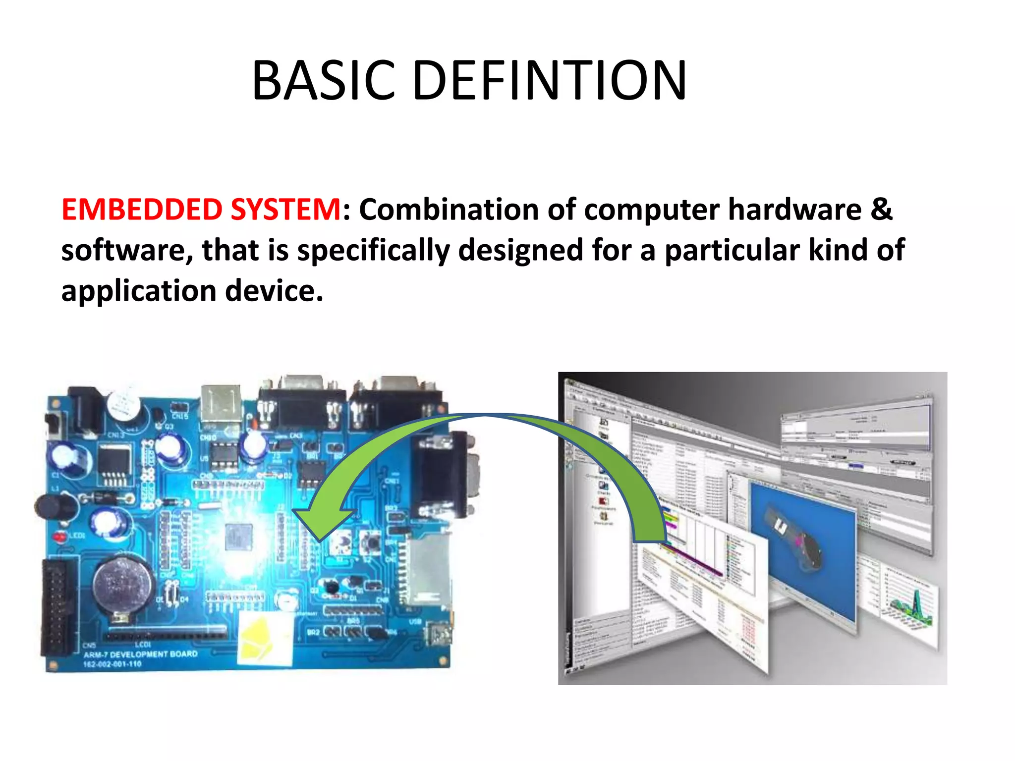
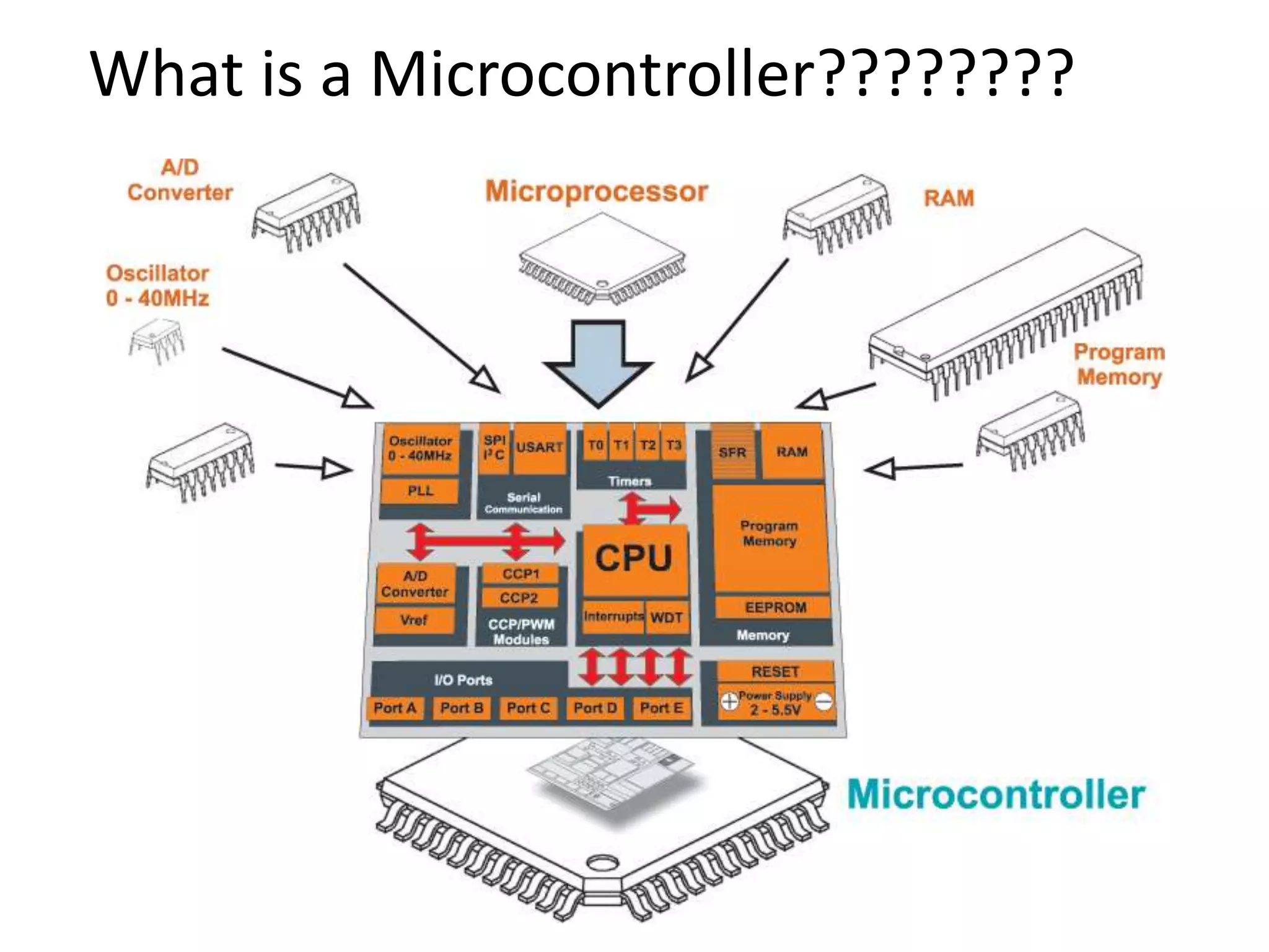
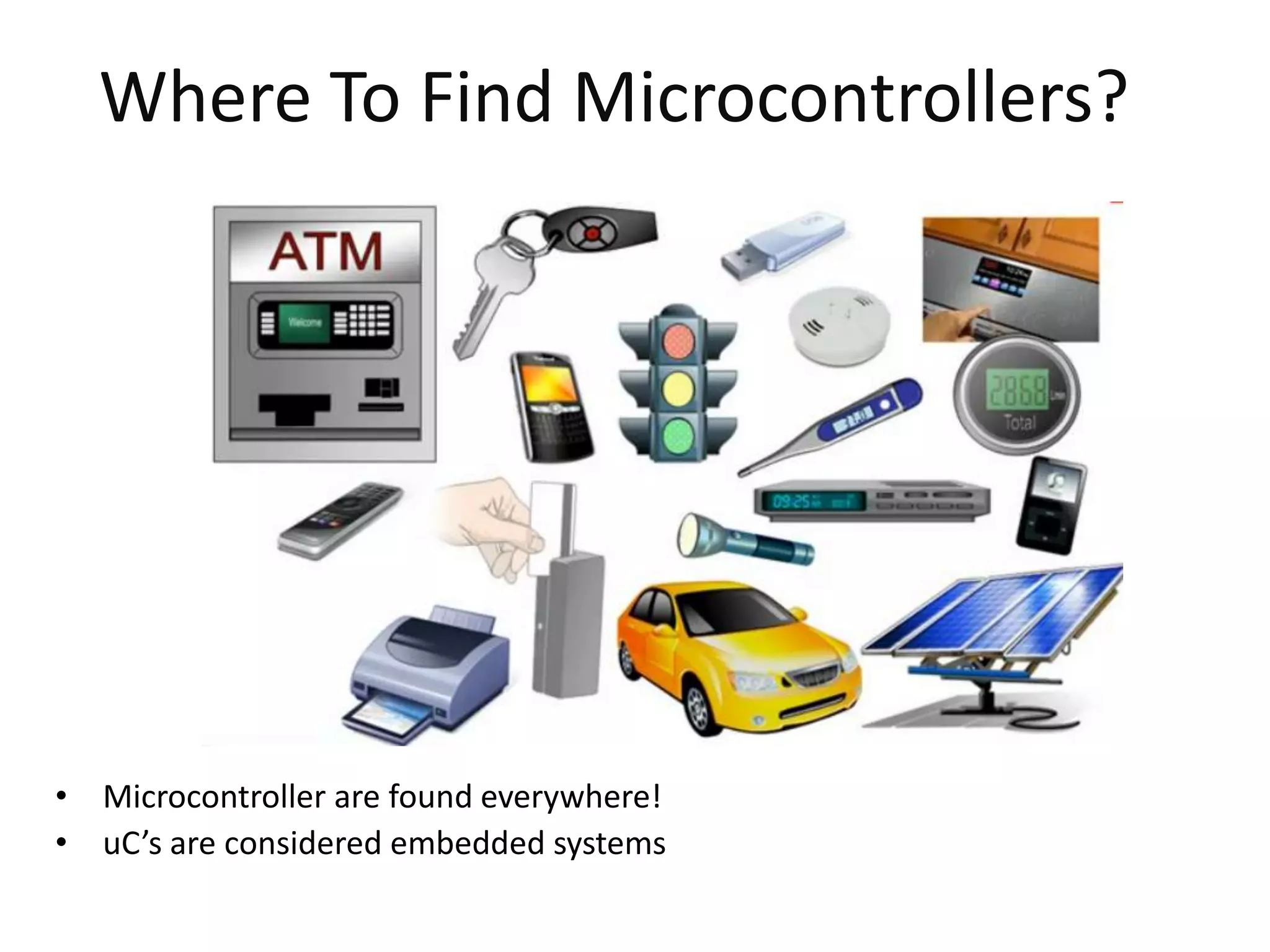
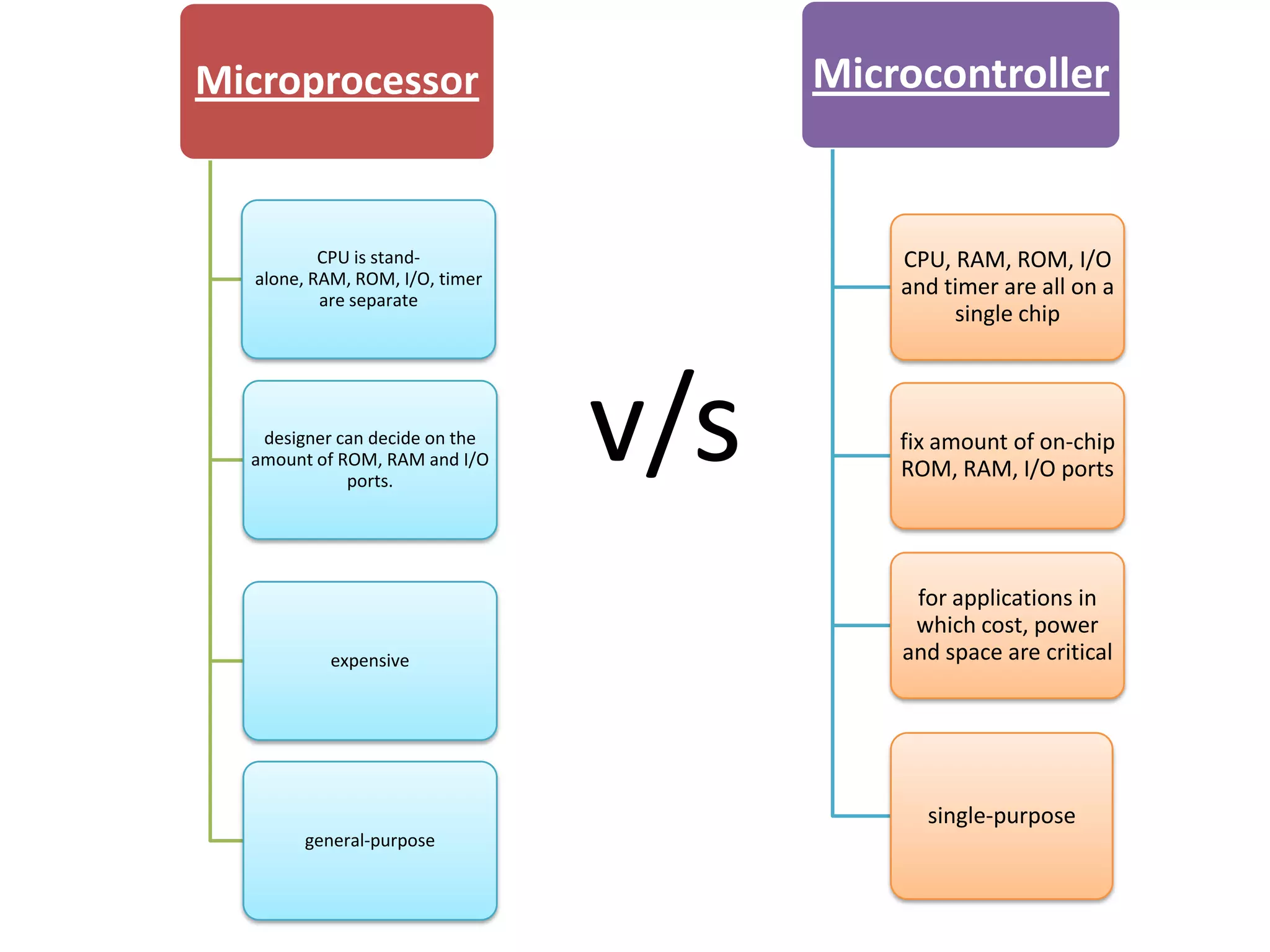
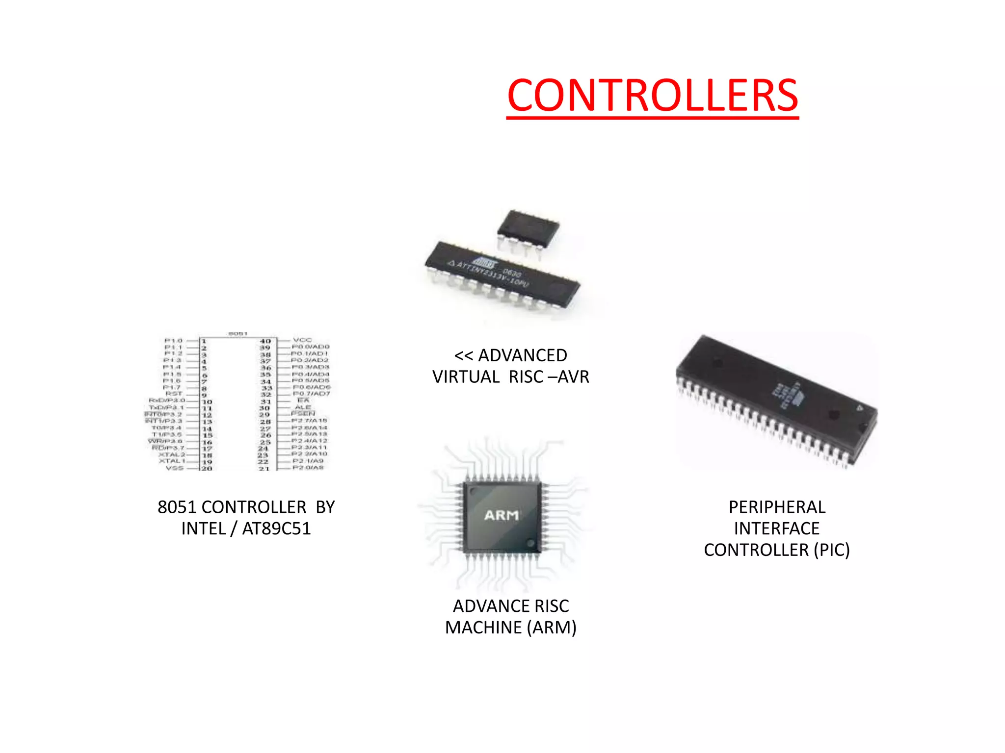
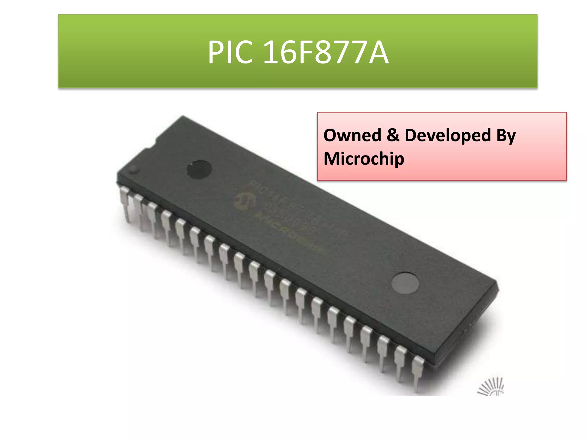
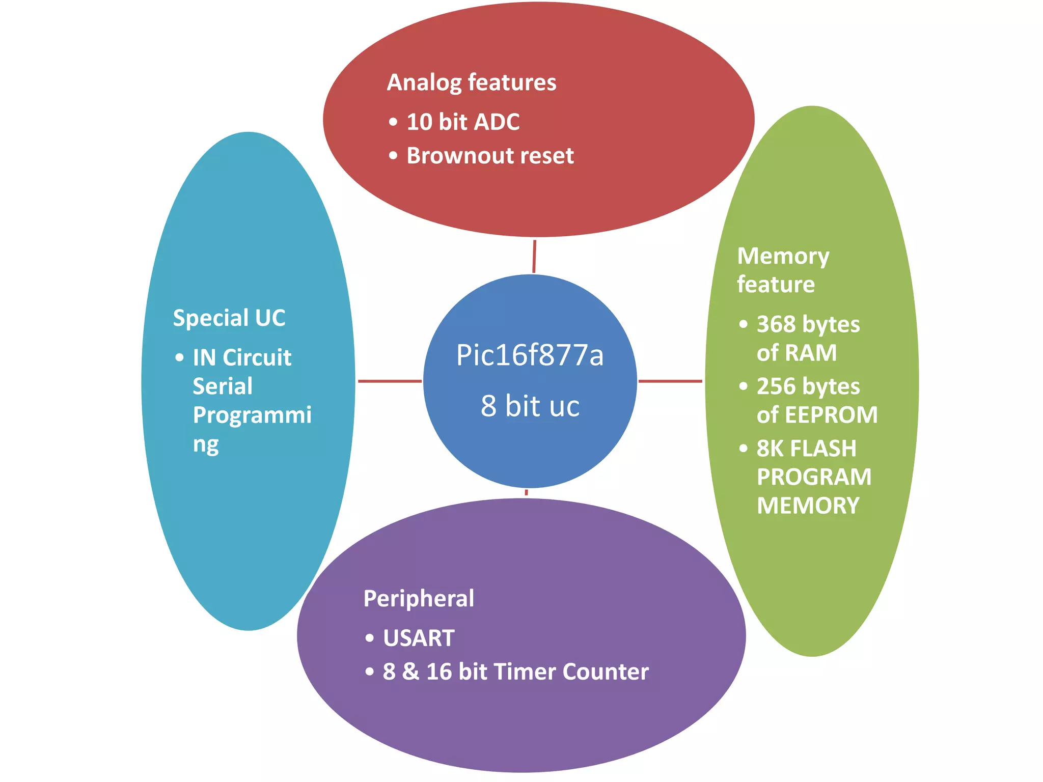
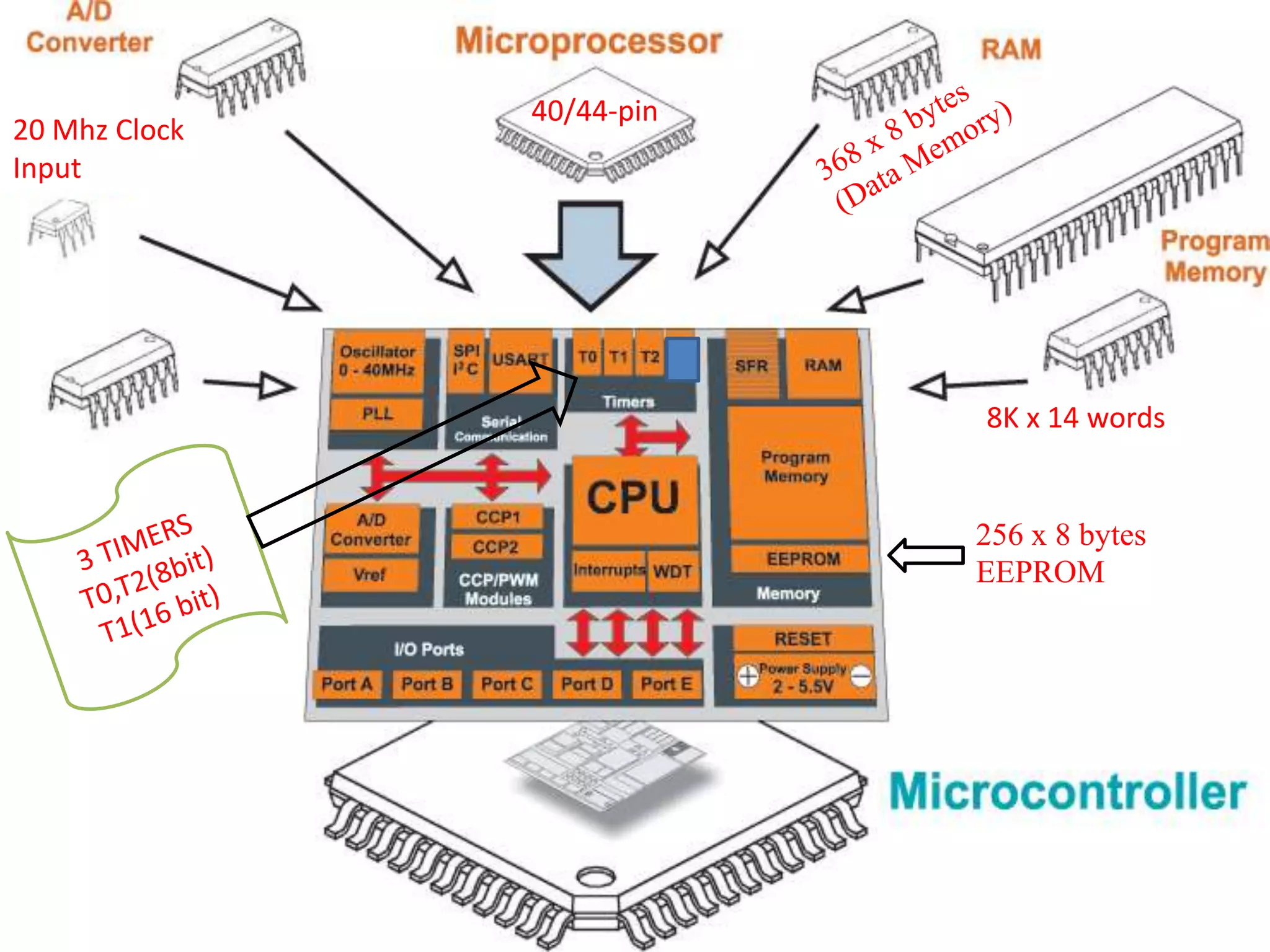
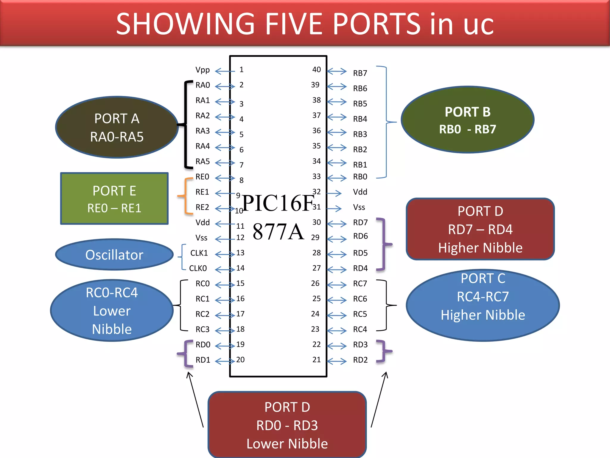
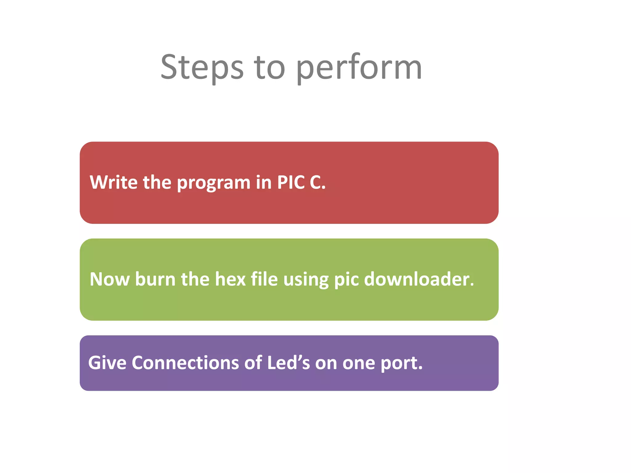
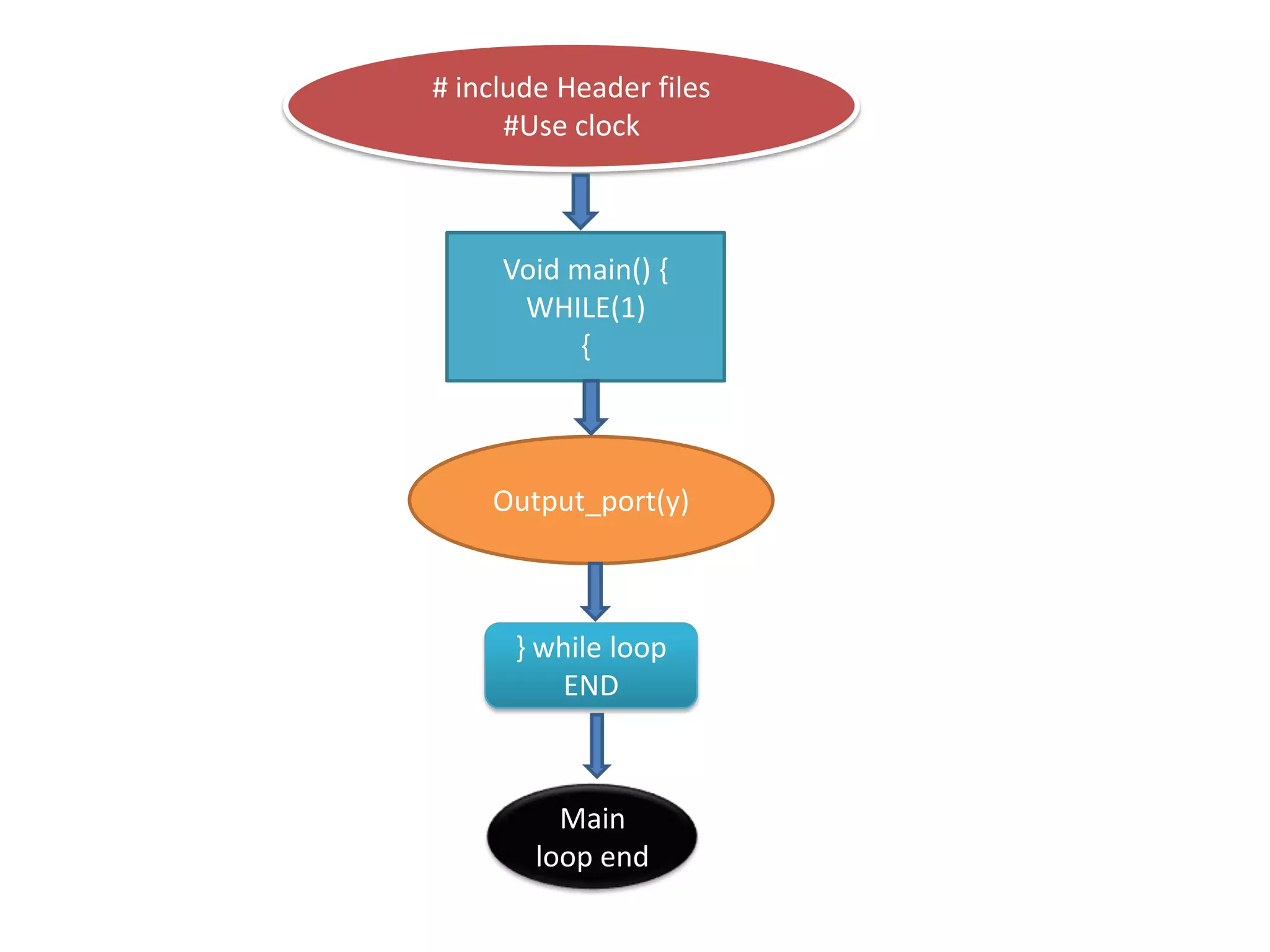
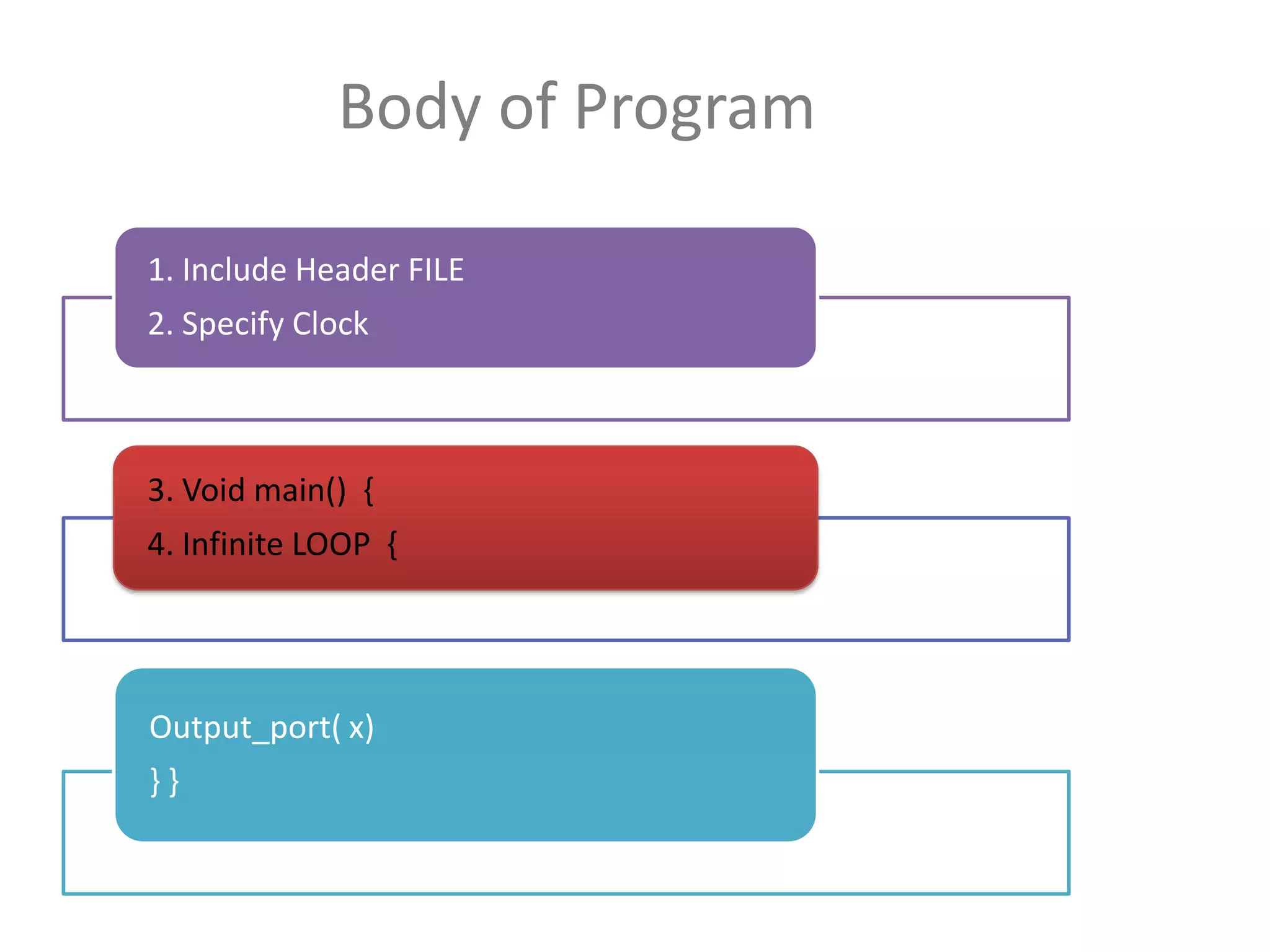
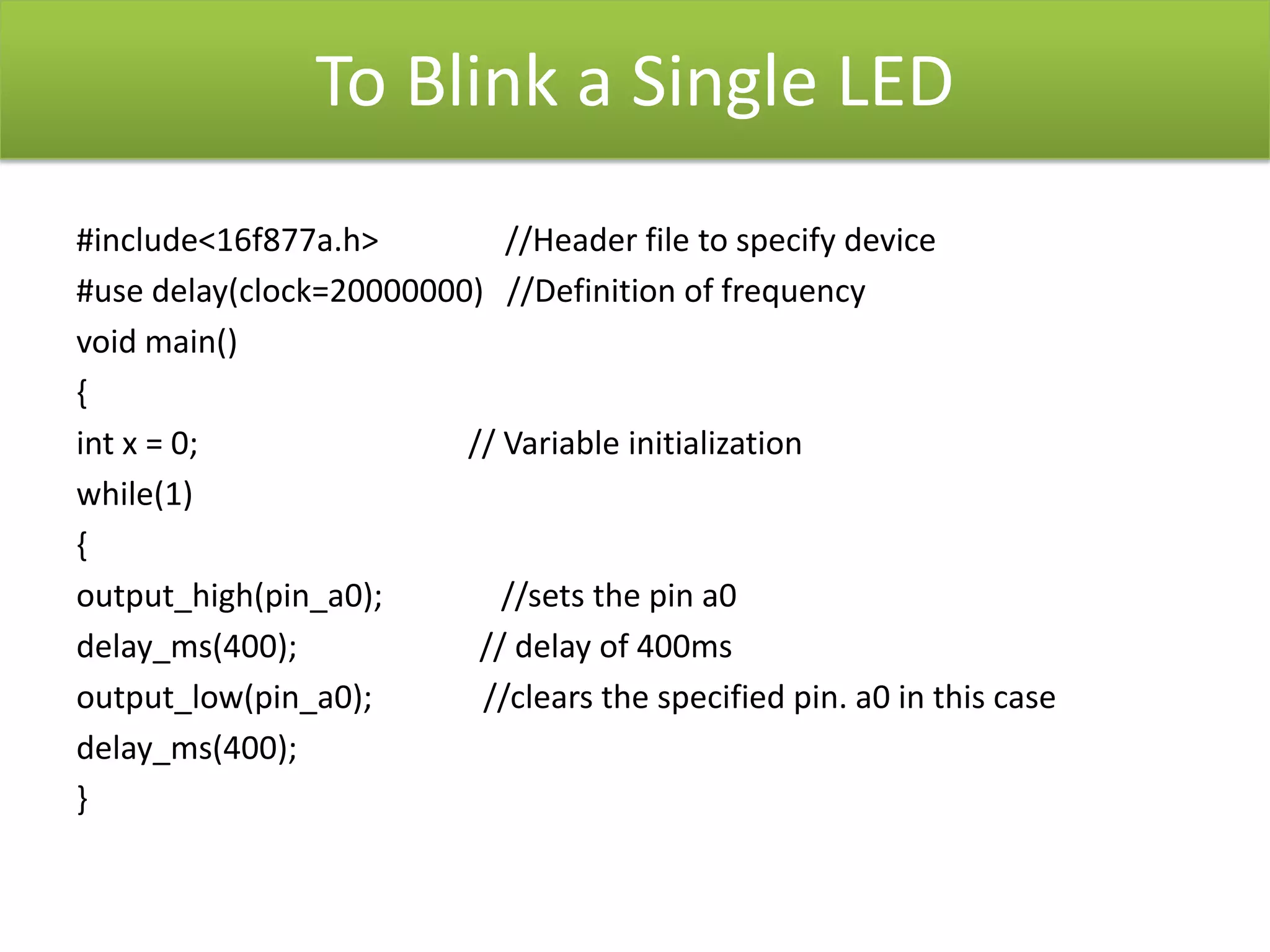
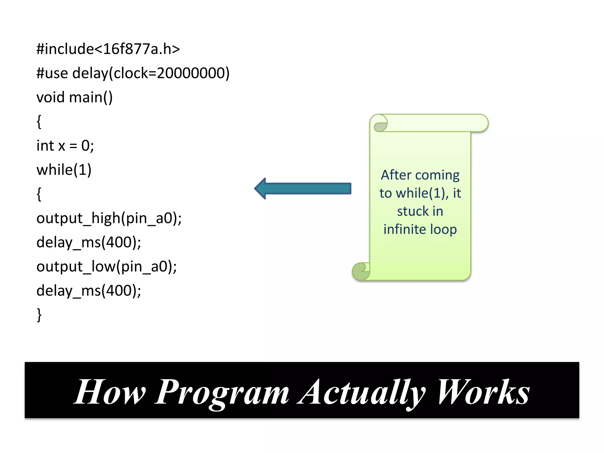
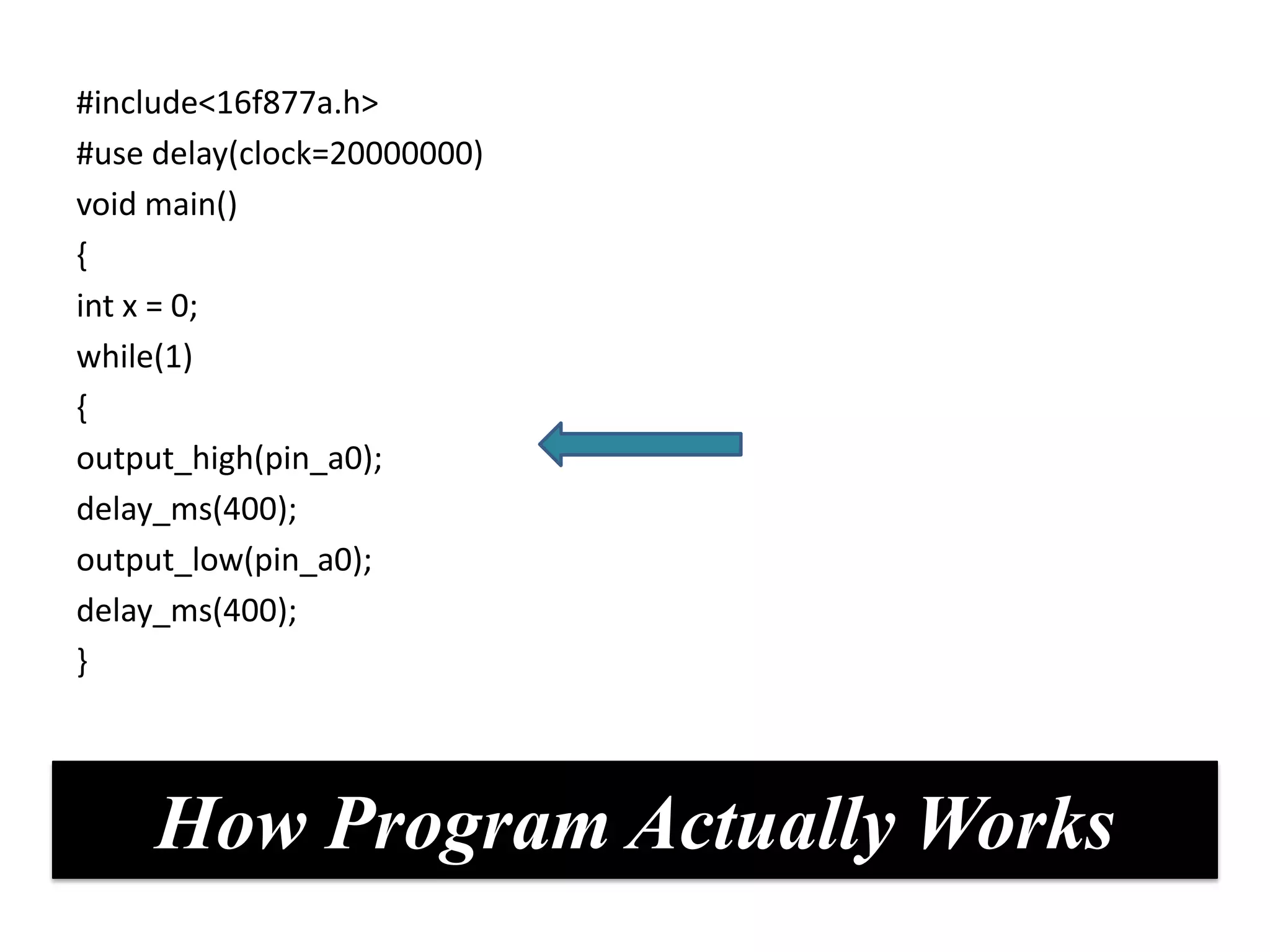
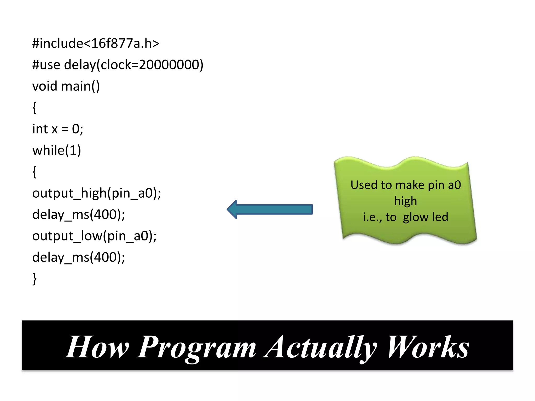
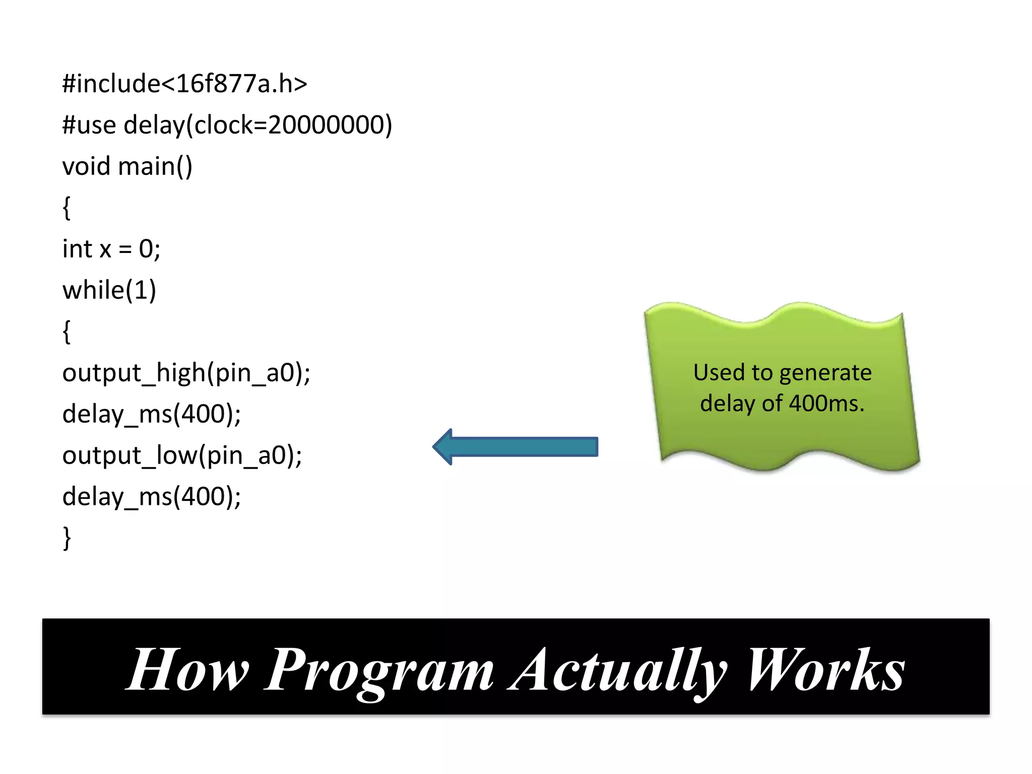
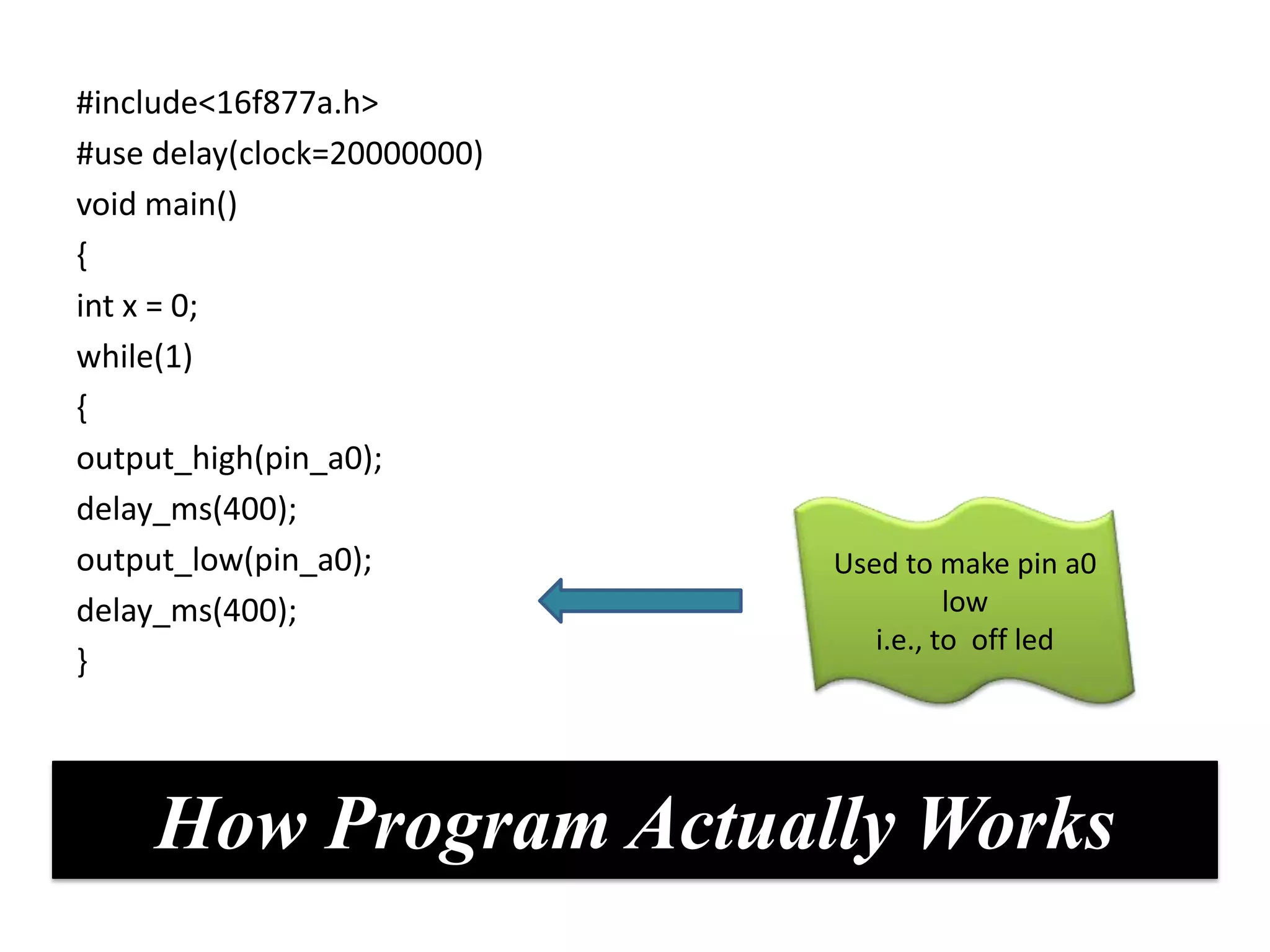
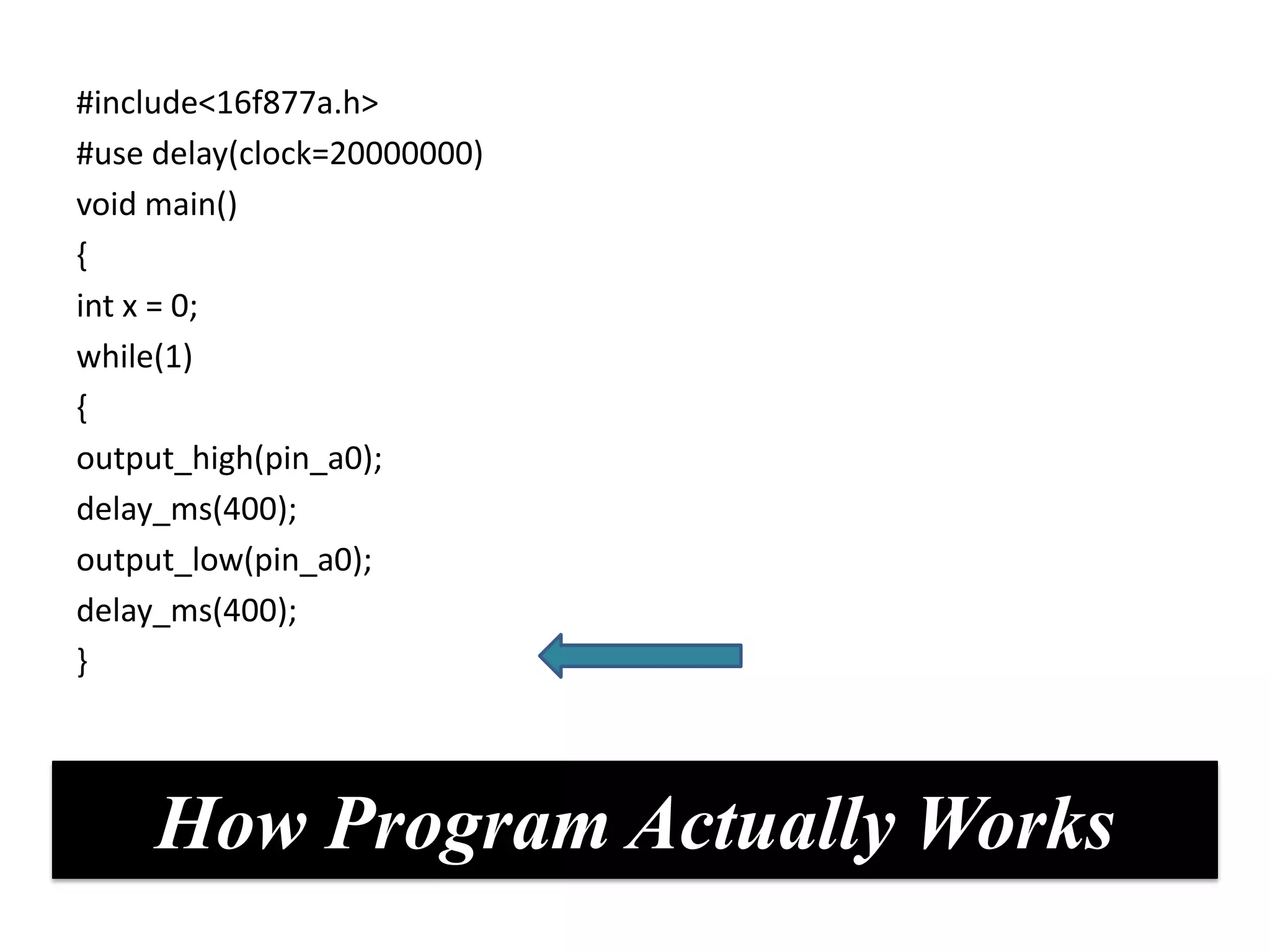
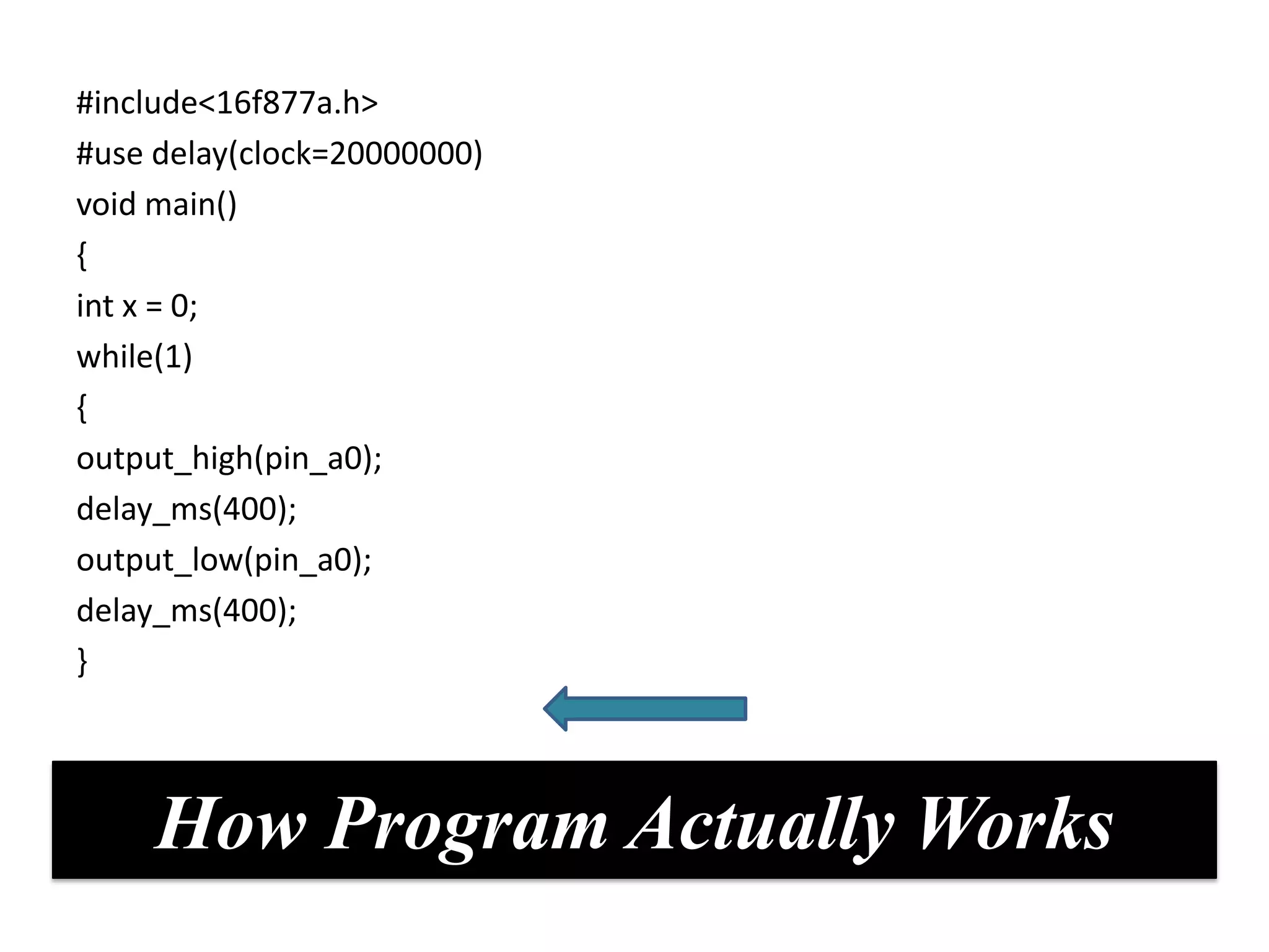
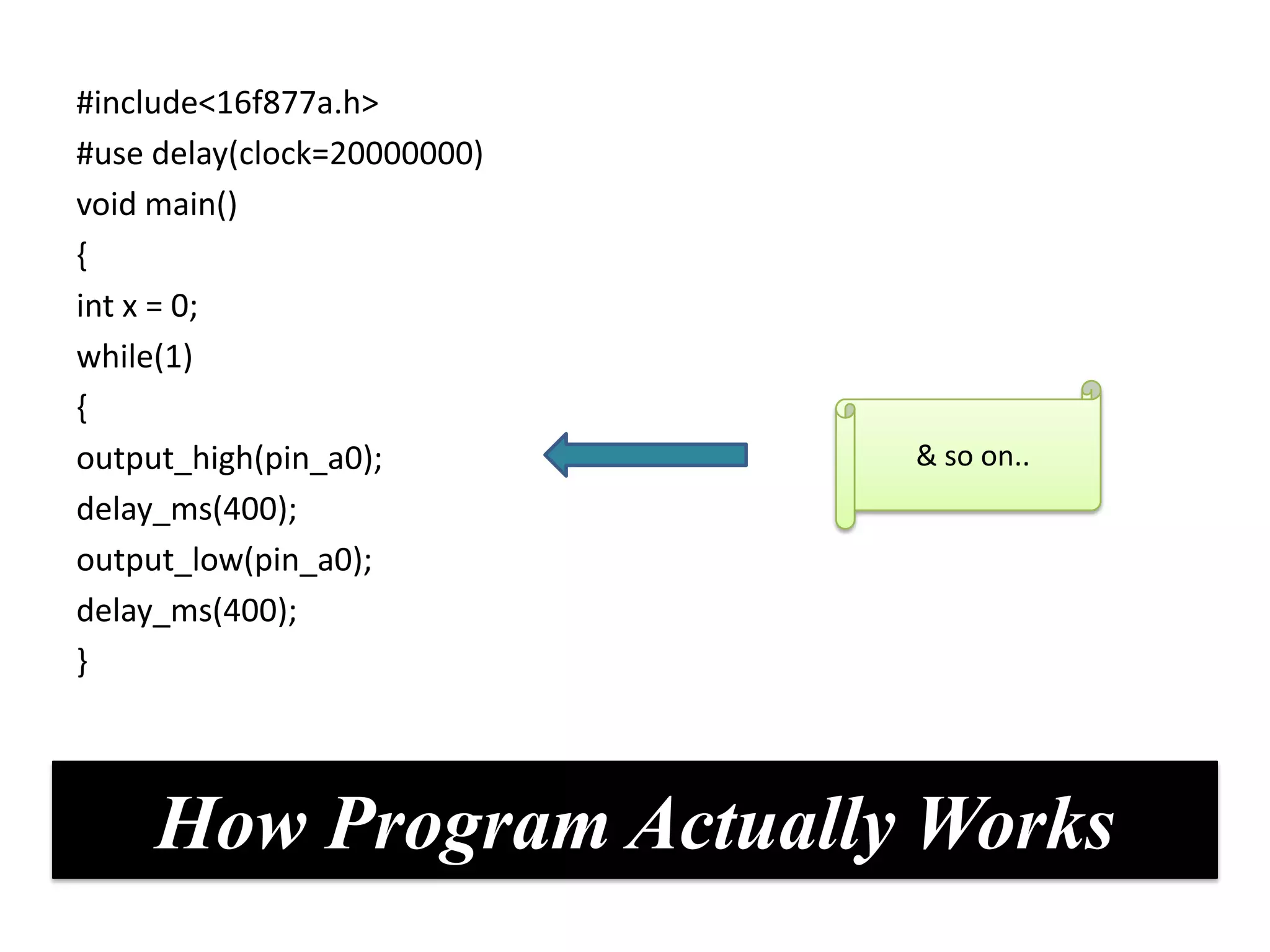
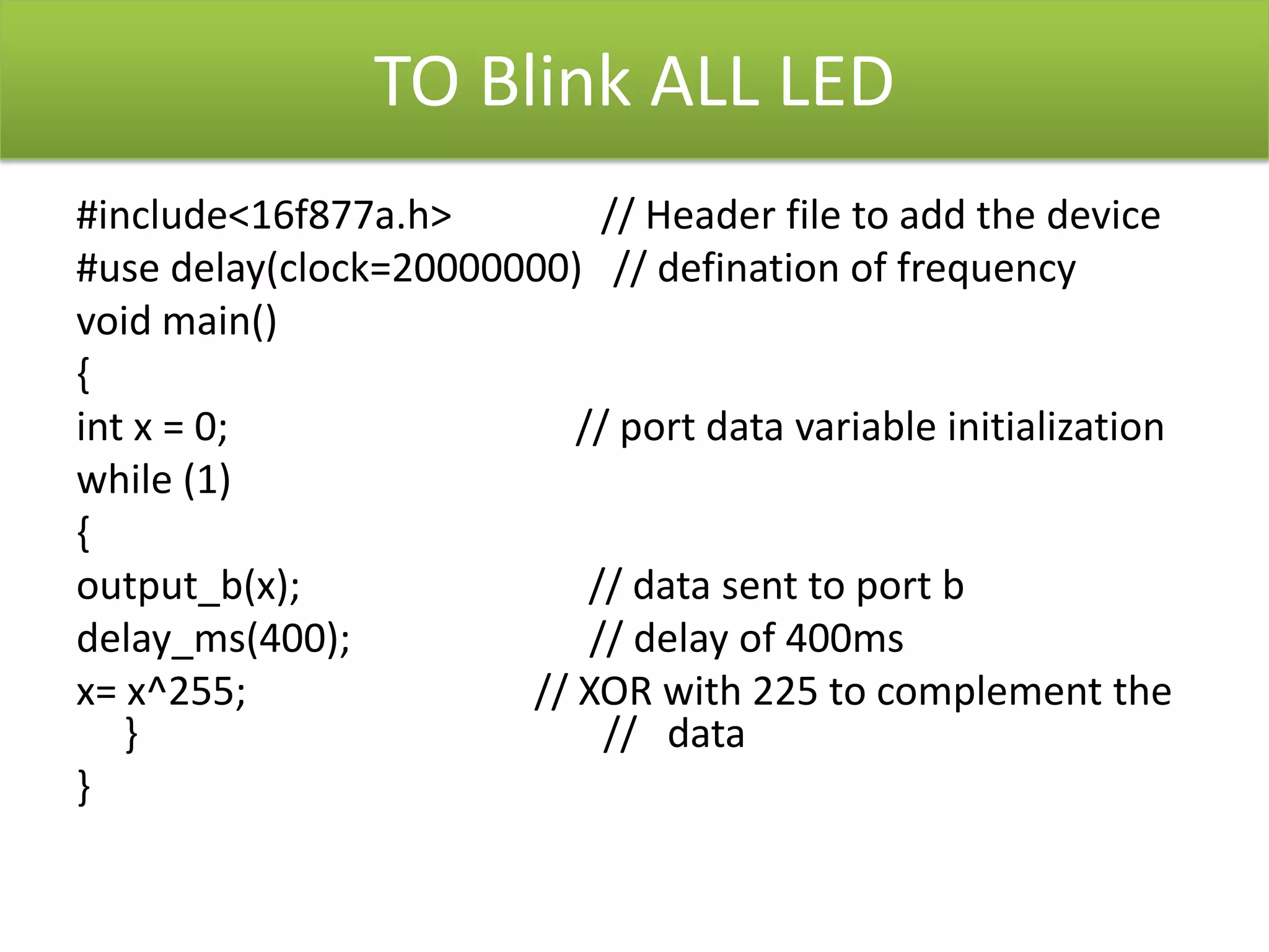
Introduction To
 Embedded System


           AR LABS
(A TRAINING UNIT OF METACORTEX
         TECHNOLOGIES)
EMBEDDED SYSTEMS ??
LITERAL MEANING
EMBEDDED        SYSTEM
BASIC DEFINTION
EMBEDDED SYSTEM: Combination of computer hardware &
software, that is specifically designed for a particular kind of
application device.
APPLICATIONS ARE NUMEROUS
APPLICATIONS OF EMBEDDED SYSTEM

 Automotive electronics


                          Aircraft

  Telecommunication


                            Trains
Specialties Of Embedded Systems


Performance       Power      Cost     Size      Software Up
               Consumption                       gradation
                                                 capability
   HIGH           LOW        CHEAP   SMALL         HIGH
BLOCK DIAGRAM OF EMBEDDED SYSTEM
CONTROLLING UNIT/BRAIN


Brain is the main part of the EMBEDDED SYSTEM
or main centre of information processing.

For an embedded system designer knowledge of
controlling unit or processor is a must.

The brain is often a microprocessor or
microcontrollers.
BRAIN

               BRAIN


Microprocessors        Microcontrollers


32 bit    64 bit       8 bit 16 bit 32 bit


    DSPs, PC           CISC        RISC
MICROPROCESSORS


                CPU for Computers
     No RAM, ROM, I/O on CPU chip itself
                 Data Bus         Many chips on mother board
      CPU
    General-
     Purpose                                           Serial
      Micro-      RAM       ROM      I/O      Timer    COM
    processor                        Port               Port


                  Address Bus

      General-Purpose Microprocessor System
Where to find microprocessors
What is a Microcontroller????????
Where To Find Microcontrollers?


• Microcontroller are found everywhere!
• uC’s are considered embedded systems
Microprocessor                        Microcontroller


          CPU is stand-                   CPU, RAM, ROM, I/O
  alone, RAM, ROM, I/O, timer             and timer are all on a
          are separate
                                               single chip


   designer can decide on the
  amount of ROM, RAM and I/O
             ports.
                                v/s       fix amount of on-chip
                                          ROM, RAM, I/O ports


                                           for applications in
                                           which cost, power
           expensive                      and space are critical


                                            single-purpose
        general-purpose
COMMONLY USED CONTROLLERS..


                         << ADVANCED
                      VIRTUAL RISC –AVR


 8051 CONTROLLER BY                         PERIPHERAL
   INTEL / AT89C51                           INTERFACE
                                          CONTROLLER (PIC)

                       ADVANCE RISC
                       MACHINE (ARM)
MICROCONTROLLER MANUFACTURERS
 o ATMEL

 o MICROCHIP

 o TEXAS INSTRUMENTS

 o INTEL

 o FREESCALE
PIC 16F877A

       Owned & Developed By
       Microchip
Analog features
                 • 10 bit ADC
                 • Brownout reset


                                            Memory
                                            feature
Special UC                                  • 368 bytes
• IN Circuit           Pic16f877a             of RAM
  Serial                                    • 256 bytes
  Programmi                 8 bit uc          of EEPROM
  ng                                        • 8K FLASH
                                              PROGRAM
                                              MEMORY


               Peripheral
               • USART
               • 8 & 16 bit Timer Counter
40/44-pin
20 Mhz Clock
Input


                           8K x 14 words


                           256 x 8 bytes
                           EEPROM
SHOWING FIVE PORTS in uc
              Vpp    1            40    RB7
              RA0    2            39    RB6
              RA1    3            38    RB5
 PORT A       RA2    4            37    RB4
                                               PORT B
              RA3                 36          RB0 - RB7
RA0-RA5       RA4
                     5
                                  35
                                        RB3
                     6                  RB2
              RA5    7            34    RB1
              RE0    8            33    RB0
 PORT E       RE1   9             32    Vdd
RE0 – RE1     RE2   10  PIC16F    31    Vss
                                                 PORT D
              Vdd   11            30    RD7
              Vss   12   877A     29    RD6
                                               RD7 – RD4
Oscillator   CLK1   13            28    RD5   Higher Nibble
             CLK0   14            27    RD4
PORT C        RC0   15            26    RC7      PORT C
RC0-RC4       RC1   16            25    RC6     RC4-RC7
 Lower        RC2   17            24    RC5   Higher Nibble
 Nibble       RC3   18            23    RC4
              RD0   19            22    RD3
              RD1   20            21    RD2


                           PORT D
                          RD0 - RD3
                         Lower Nibble
Steps to perform

Write the program in PIC C.


Now burn the hex file using pic downloader.


Give Connections of Led’s on one port.
Points To                    Remember


We have 5 bidirectional PORTS in our controller.

Any peripheral will be connected to these ports only.

The value on these ports decides the functionality of
peripheral
Points To                   Remember
 There are some predefined functions under the header
file <pic16f877a.h> which we use

1.output_low(pin_x): Used to make particular pin low(0)

2.output_high(pin_x):Used to make particular pin
high(1)

3.Output_port(value): using this function ,value is
loaded on the port.
1=ON


                            0=Off
For e.g. we want to send
a value like 15 on port B

   In binary It means
       00001111
      We will write
    Output_port(15)


Red = on =1
Blue =Off=0
another e.g.
we want to send value
 now 116 on port D

  In binary It means
      01110100
     We will write
  Output_port(116)


Red = on =1
Blue =Off=0
# include Header files
      #Use clock


     Void main() {
      WHILE(1)
           {


    Output_port(y)


      } while loop
          END


          Main
        loop end
Body of Program

1. Include Header FILE
2. Specify Clock


3. Void main() {
4. Infinite LOOP {


Output_port( x)
}}
To Blink a Single LED
#include<16f877a.h>         //Header file to specify device
#use delay(clock=20000000) //Definition of frequency
void main()
{
int x = 0;               // Variable initialization
while(1)
{
output_high(pin_a0);        //sets the pin a0
delay_ms(400);            // delay of 400ms
output_low(pin_a0);       //clears the specified pin. a0 in this case
delay_ms(400);
}
#include<16f877a.h>
#use delay(clock=20000000)
void main()
{
int x = 0;
while(1)                     After coming
{                            to while(1), it
output_high(pin_a0);             stuck in
                              infinite loop
delay_ms(400);
output_low(pin_a0);
delay_ms(400);
}


     How Program Actually Works
#include<16f877a.h>
#use delay(clock=20000000)
void main()
{
int x = 0;
while(1)
{
output_high(pin_a0);
delay_ms(400);
output_low(pin_a0);
delay_ms(400);
}


     How Program Actually Works
#include<16f877a.h>
#use delay(clock=20000000)
void main()
{
int x = 0;
while(1)
{
                             Used to make pin a0
output_high(pin_a0);
                                       high
delay_ms(400);                 i.e., to glow led
output_low(pin_a0);
delay_ms(400);
}


     How Program Actually Works
#include<16f877a.h>
#use delay(clock=20000000)
void main()
{
int x = 0;
while(1)
{
output_high(pin_a0);         Used to generate
delay_ms(400);               delay of 400ms.

output_low(pin_a0);
delay_ms(400);
}


     How Program Actually Works
#include<16f877a.h>
#use delay(clock=20000000)
void main()
{
int x = 0;
while(1)
{
output_high(pin_a0);
delay_ms(400);
output_low(pin_a0);          Used to make pin a0
delay_ms(400);                         low
                                i.e., to off led
}


     How Program Actually Works
#include<16f877a.h>
#use delay(clock=20000000)
void main()
{
int x = 0;
while(1)
{
output_high(pin_a0);
delay_ms(400);
output_low(pin_a0);
delay_ms(400);
}


     How Program Actually Works
#include<16f877a.h>
#use delay(clock=20000000)
void main()
{
int x = 0;
while(1)
{
output_high(pin_a0);
delay_ms(400);
output_low(pin_a0);
delay_ms(400);
}


     How Program Actually Works
#include<16f877a.h>
#use delay(clock=20000000)
void main()
{
int x = 0;
while(1)
{
output_high(pin_a0);         & so on..
delay_ms(400);
output_low(pin_a0);
delay_ms(400);
}


     How Program Actually Works
TO Blink ALL LED
#include<16f877a.h>         // Header file to add the device
#use delay(clock=20000000) // defination of frequency
void main()
{
int x = 0;                // port data variable initialization
while (1)
{
output_b(x);               // data sent to port b
delay_ms(400);             // delay of 400ms
x= x^255;              // XOR with 225 to complement the
   }                        // data
}

Basics Of Embedded Systems

  • 1.
    Introduction To EmbeddedSystem AR LABS (A TRAINING UNIT OF METACORTEX TECHNOLOGIES)
  • 2.
  • 3.
  • 4.
    BASIC DEFINTION EMBEDDED SYSTEM:Combination of computer hardware & software, that is specifically designed for a particular kind of application device.
  • 5.
  • 6.
    APPLICATIONS OF EMBEDDEDSYSTEM Automotive electronics Aircraft Telecommunication Trains
  • 8.
    Specialties Of EmbeddedSystems Performance Power Cost Size Software Up Consumption gradation capability HIGH LOW CHEAP SMALL HIGH
  • 9.
    BLOCK DIAGRAM OFEMBEDDED SYSTEM
  • 10.
    CONTROLLING UNIT/BRAIN Brain isthe main part of the EMBEDDED SYSTEM or main centre of information processing. For an embedded system designer knowledge of controlling unit or processor is a must. The brain is often a microprocessor or microcontrollers.
  • 11.
    BRAIN BRAIN Microprocessors Microcontrollers 32 bit 64 bit 8 bit 16 bit 32 bit DSPs, PC CISC RISC
  • 12.
    MICROPROCESSORS CPU for Computers No RAM, ROM, I/O on CPU chip itself Data Bus Many chips on mother board CPU General- Purpose Serial Micro- RAM ROM I/O Timer COM processor Port Port Address Bus General-Purpose Microprocessor System
  • 13.
    Where to findmicroprocessors
  • 14.
    What is aMicrocontroller????????
  • 15.
    Where To FindMicrocontrollers? • Microcontroller are found everywhere! • uC’s are considered embedded systems
  • 16.
    Microprocessor Microcontroller CPU is stand- CPU, RAM, ROM, I/O alone, RAM, ROM, I/O, timer and timer are all on a are separate single chip designer can decide on the amount of ROM, RAM and I/O ports. v/s fix amount of on-chip ROM, RAM, I/O ports for applications in which cost, power expensive and space are critical single-purpose general-purpose
  • 17.
    COMMONLY USED CONTROLLERS.. << ADVANCED VIRTUAL RISC –AVR 8051 CONTROLLER BY PERIPHERAL INTEL / AT89C51 INTERFACE CONTROLLER (PIC) ADVANCE RISC MACHINE (ARM)
  • 18.
    MICROCONTROLLER MANUFACTURERS oATMEL o MICROCHIP o TEXAS INSTRUMENTS o INTEL o FREESCALE
  • 19.
    PIC 16F877A Owned & Developed By Microchip
  • 21.
    Analog features • 10 bit ADC • Brownout reset Memory feature Special UC • 368 bytes • IN Circuit Pic16f877a of RAM Serial • 256 bytes Programmi 8 bit uc of EEPROM ng • 8K FLASH PROGRAM MEMORY Peripheral • USART • 8 & 16 bit Timer Counter
  • 22.
    40/44-pin 20 Mhz Clock Input 8K x 14 words 256 x 8 bytes EEPROM
  • 23.
    SHOWING FIVE PORTSin uc Vpp 1 40 RB7 RA0 2 39 RB6 RA1 3 38 RB5 PORT A RA2 4 37 RB4 PORT B RA3 36 RB0 - RB7 RA0-RA5 RA4 5 35 RB3 6 RB2 RA5 7 34 RB1 RE0 8 33 RB0 PORT E RE1 9 32 Vdd RE0 – RE1 RE2 10 PIC16F 31 Vss PORT D Vdd 11 30 RD7 Vss 12 877A 29 RD6 RD7 – RD4 Oscillator CLK1 13 28 RD5 Higher Nibble CLK0 14 27 RD4 PORT C RC0 15 26 RC7 PORT C RC0-RC4 RC1 16 25 RC6 RC4-RC7 Lower RC2 17 24 RC5 Higher Nibble Nibble RC3 18 23 RC4 RD0 19 22 RD3 RD1 20 21 RD2 PORT D RD0 - RD3 Lower Nibble
  • 25.
    Steps to perform Writethe program in PIC C. Now burn the hex file using pic downloader. Give Connections of Led’s on one port.
  • 26.
    Points To Remember We have 5 bidirectional PORTS in our controller. Any peripheral will be connected to these ports only. The value on these ports decides the functionality of peripheral
  • 27.
    Points To Remember There are some predefined functions under the header file <pic16f877a.h> which we use 1.output_low(pin_x): Used to make particular pin low(0) 2.output_high(pin_x):Used to make particular pin high(1) 3.Output_port(value): using this function ,value is loaded on the port.
  • 28.
    1=ON 0=Off For e.g. we want to send a value like 15 on port B In binary It means 00001111 We will write Output_port(15) Red = on =1 Blue =Off=0
  • 29.
    another e.g. we wantto send value now 116 on port D In binary It means 01110100 We will write Output_port(116) Red = on =1 Blue =Off=0
  • 30.
    # include Headerfiles #Use clock Void main() { WHILE(1) { Output_port(y) } while loop END Main loop end
  • 31.
    Body of Program 1.Include Header FILE 2. Specify Clock 3. Void main() { 4. Infinite LOOP { Output_port( x) }}
  • 32.
    To Blink aSingle LED #include<16f877a.h> //Header file to specify device #use delay(clock=20000000) //Definition of frequency void main() { int x = 0; // Variable initialization while(1) { output_high(pin_a0); //sets the pin a0 delay_ms(400); // delay of 400ms output_low(pin_a0); //clears the specified pin. a0 in this case delay_ms(400); }
  • 33.
    #include<16f877a.h> #use delay(clock=20000000) void main() { intx = 0; while(1) After coming { to while(1), it output_high(pin_a0); stuck in infinite loop delay_ms(400); output_low(pin_a0); delay_ms(400); } How Program Actually Works
  • 34.
    #include<16f877a.h> #use delay(clock=20000000) void main() { intx = 0; while(1) { output_high(pin_a0); delay_ms(400); output_low(pin_a0); delay_ms(400); } How Program Actually Works
  • 35.
    #include<16f877a.h> #use delay(clock=20000000) void main() { intx = 0; while(1) { Used to make pin a0 output_high(pin_a0); high delay_ms(400); i.e., to glow led output_low(pin_a0); delay_ms(400); } How Program Actually Works
  • 36.
    #include<16f877a.h> #use delay(clock=20000000) void main() { intx = 0; while(1) { output_high(pin_a0); Used to generate delay_ms(400); delay of 400ms. output_low(pin_a0); delay_ms(400); } How Program Actually Works
  • 37.
    #include<16f877a.h> #use delay(clock=20000000) void main() { intx = 0; while(1) { output_high(pin_a0); delay_ms(400); output_low(pin_a0); Used to make pin a0 delay_ms(400); low i.e., to off led } How Program Actually Works
  • 38.
    #include<16f877a.h> #use delay(clock=20000000) void main() { intx = 0; while(1) { output_high(pin_a0); delay_ms(400); output_low(pin_a0); delay_ms(400); } How Program Actually Works
  • 39.
    #include<16f877a.h> #use delay(clock=20000000) void main() { intx = 0; while(1) { output_high(pin_a0); delay_ms(400); output_low(pin_a0); delay_ms(400); } How Program Actually Works
  • 40.
    #include<16f877a.h> #use delay(clock=20000000) void main() { intx = 0; while(1) { output_high(pin_a0); & so on.. delay_ms(400); output_low(pin_a0); delay_ms(400); } How Program Actually Works
  • 41.
    TO Blink ALLLED #include<16f877a.h> // Header file to add the device #use delay(clock=20000000) // defination of frequency void main() { int x = 0; // port data variable initialization while (1) { output_b(x); // data sent to port b delay_ms(400); // delay of 400ms x= x^255; // XOR with 225 to complement the } // data }