Downloaded 26 times
![INTRODUCTION TO MICROCONTROLLERS
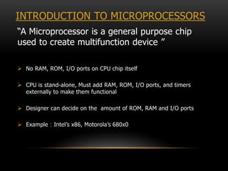
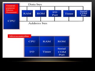
“A Microcontroller is a specific computer-on-a-
chip optimized to control Electronic devices”
CPU + I/O + Timer(s) [+ ROM] [+ RAM] All on single chip
Limited RAM space, ROM space and I/O pins
Low chip-count to implement a small system
Low-cost at large quantities
Development tools readily available at reasonable cost](https://image.slidesharecdn.com/seminaronembedded-150917190457-lva1-app6891/85/embedded-system-11-320.jpg)
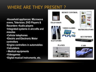


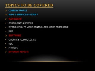
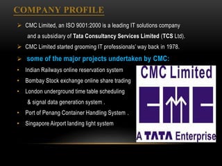
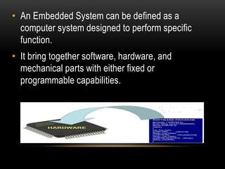
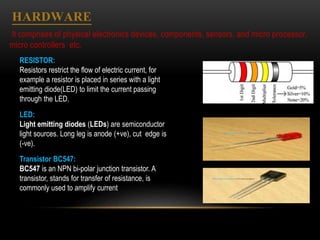
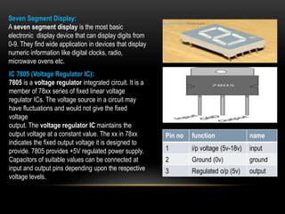
This document provides a summary of a practical training seminar report on embedded systems conducted at CMC Academy in Jaipur. It discusses the company profile of CMC Academy, provides definitions and comparisons of microprocessors and microcontrollers. It also describes some common electronic components used in embedded systems like resistors, LEDs, transistors, integrated circuits. Programming concepts for 8051 microcontrollers like I/O ports, timers and interrupts are explained. The document concludes by noting the widespread use of embedded systems in appliances, vehicles, medical devices and more.