Downloaded 109 times
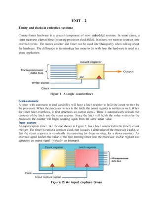
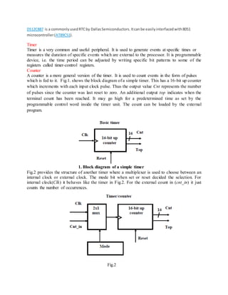
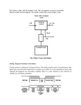
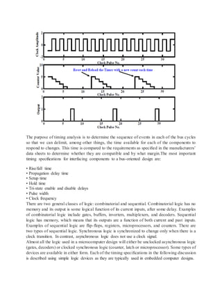
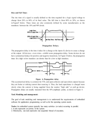
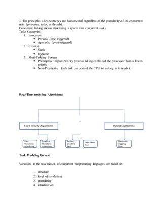

The document discusses timing and clocks in embedded systems. It describes different types of timers/counters used in embedded systems like real-time clocks, input capture timers, and timers with automatic reload capability. It also discusses timing diagram notations, timing specifications like rise/fall times, propagation delays, setup and hold times. Real-time clocks provide precise timekeeping and are useful for applications requiring time stamps. Counters are used to count external events while timers generate interrupts at specific time intervals. Timing analysis is important to ensure components can interface properly based on their timing requirements.