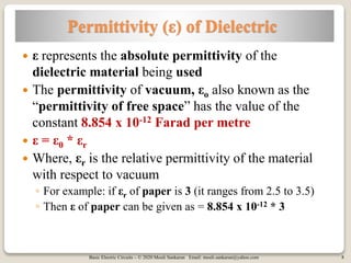
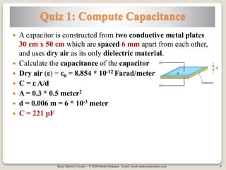
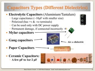
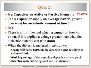
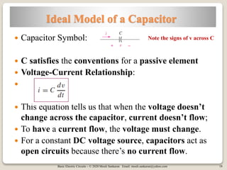
Basic Electric Circuits – © 2020 Mouli Sankaran Email: mouli.sankaran@yahoo.com
Basic Electric Circuits – © 2020 Mouli Sankaran Email: mouli.sankaran@yahoo.com 2
Session 15B: Focus
 Charging of Capacitor Explained
 Capacitor Properties
◦ Capacitor Value (in terms of construction parameters)
◦ Electric Field and Voltage
 Ideal Capacitor Model
Basic Electric Circuits – © 2020 Mouli Sankaran Email: mouli.sankaran@yahoo.com
Charging of Capacitor Explained
Basic Electric Circuits – © 2020 Mouli Sankaran Email: mouli.sankaran@yahoo.com 4
Charging of a Capacitor Explained
 The fields from these extra electrons reach across the gap
between the plates, forcing an equal number of electrons to
simultaneously flow out of the other plate and into the power
supply. (called displacement current)
 This creates opposite areas of imbalanced charge within capacitor
 One plate has less electrons and excess protons, and the other
plate has more electrons than protons.
 Thus, one plate has more of positive charges and the other has
more of electrons (negative charges)
4
 When we "charge" a conventional metal-
plate capacitor, the power supply pushes
electrons into one plate, and
Basic Electric Circuits – © 2020 Mouli Sankaran Email: mouli.sankaran@yahoo.com 5
Charging of a Capacitor … contd.
 However, if we consider the capacitor as a whole, no electrons
have been put into the capacitor on none have been removed.
 The same number of electrons are in a "charged" capacitor as
in a capacitor which has been totally "discharged.“
 Yes, a certain amount of charge has been forced to flow
momentarily during "charging," and a rising potential
difference has appeared across the capacitor
 The amount of charge inside the capacitor never changes.
 The net charge on each plate is cancelled by the opposite
charge on the other plate
5
Basic Electric Circuits – © 2020 Mouli Sankaran Email: mouli.sankaran@yahoo.com
Capacitor Value
In terms of
Construction Parameters
Basic Electric Circuits – © 2020 Mouli Sankaran Email: mouli.sankaran@yahoo.com 7
Capacitance Value
 C = εA/d
 If Area of the plates is large, more
charge (Q) imbalance can be created
within the capacitor
 If d is smaller, the attractive force
between the plates (with opposite
charges) help in holding more charges of
the same sign on each plates, thus
improving the capacitance
ε: Dielectric constant of dielectric material used
A: Area of metallic plates
d: Distance between the plates Plates separated
By infinite distance
Closer distance
Very close
What is the unit of ε?
Farad/meter
Basic Electric Circuits – © 2020 Mouli Sankaran Email: mouli.sankaran@yahoo.com 8
Permittivity (ε) of Dielectric
 ε represents the absolute permittivity of the
dielectric material being used
 The permittivity of vacuum, εo also known as the
“permittivity of free space” has the value of the
constant 8.854 x 10⁻¹² Farad per metre
 ε = ε0 * εr
 Where, εr is the relative permittivity of the material
with respect to vacuum
◦ For example: if εr of paper is 3 (it ranges from 2.5 to 3.5)
◦ Then ε of paper can be given as = 8.854 x 10-12 * 3
Basic Electric Circuits – © 2020 Mouli Sankaran Email: mouli.sankaran@yahoo.com 9
Quiz 1: Compute Capacitance
 A capacitor is constructed from two conductive metal plates
30 cm x 50 cm which are spaced 6 mm apart from each other,
and uses dry air as its only dielectric material.
 Calculate the capacitance of the capacitor
 Dry air (ε) = ε0 = 8.854 * 10-12 Farad/meter
 C = ε A/d
 A = 0.3 * 0.5 meter2
 d = 0.006 m = 6 * 10-3 meter
 C = 221 pF
Basic Electric Circuits – © 2020 Mouli Sankaran Email: mouli.sankaran@yahoo.com 10
Capacitors Types (Different Dielectrics)
 Electrolytic Capacitors (Aluminium/Tantalum)
◦ Large capacitance (~10μF with smaller size)
◦ Polarized (has +v & -ve terminals)
◦ Can be used only with DC power supply
◦ Permanent damage, if connected incorrectly
 Mylar capacitors
 Gang capacitors
 Paper Capacitors
 Ceramic Capacitors:
◦ A few pF to 1or 2 μF
Air as dielectric
Basic Electric Circuits – © 2020 Mouli Sankaran Email: mouli.sankaran@yahoo.com
Electric Field and Voltage
Basic Electric Circuits – © 2020 Mouli Sankaran Email: mouli.sankaran@yahoo.com 12
Electric Field (E) within a Capacitor
• For an INFINITE parallel plate
capacitor, the electric field has
the same value everywhere
between the 2 plates.
12
• Assume a test charge +q is inside, it will experience the
same force (E) at every point inside, due to repulsive
force from +ve plate and attractive force from the –ve
plate change in unison
• When one increases by some amount, the other decreases by
the same amount
• Keeping E uniform at all places within a capacitor
Basic Electric Circuits – © 2020 Mouli Sankaran Email: mouli.sankaran@yahoo.com 14
Electric Field Between the Plates
 A parallel-plate capacitor with no dielectric between the plates,
results in a larger electric field (E)
 If there is a dielectric material present, E is reduced between the
plates because dielectric is polarized, producing an opposite
electric field inside
 When E is reduced, V across the plates comes down, causing
more charge (Q) build up on the plates
Basic Electric Circuits – © 2020 Mouli Sankaran Email: mouli.sankaran@yahoo.com
Ideal Capacitor Model
Basic Electric Circuits – © 2020 Mouli Sankaran Email: mouli.sankaran@yahoo.com 16
Active and Passive Elements
 Active Element:
◦ An element that is capable of furnishing an average power
greater than zero to some external device, where the
average is taken over an infinite time interval
 Passive Element:
◦ An element that cannot supply an average power that is
greater than zero over an infinite time interval
 Independent Voltage and Current sources:
 Resistors:
◦ Resistor falls into this category; as the energy it receives is
usually transformed into heat,
◦ And it never supplies energy.
Active
Passive
Basic Electric Circuits – © 2020 Mouli Sankaran Email: mouli.sankaran@yahoo.com 17
Quiz 2:
 Is a Capacitor an Active or Passive Element?
 Can a Capacitor supply an average power (greater
than zero) for an infinite amount of time?
 NO
 There is a limit beyond which a capacitor breaks
down, if it is applied a voltage greater than what the
dielectric material can withstand
 When the dielectric material breaks down
◦ Arcing will occur between the capacitor plates resulting in
a short-circuit
◦ Working voltage of the capacitor depends on the type of
dielectric material being used and its thickness
Passive
Basic Electric Circuits – © 2020 Mouli Sankaran Email: mouli.sankaran@yahoo.com 18
Ideal Model of a Capacitor
 Capacitor Symbol:
 C satisfies the conventions for a passive element
 Voltage-Current Relationship:

 This equation tells us that when the voltage doesn’t
change across the capacitor, current doesn’t flow;
 To have a current flow, the voltage must change.
 For a constant DC voltage source, capacitors act as
open circuits because there’s no current flow.
Note the signs of v across C
Basic Electric Circuits – © 2020 Mouli Sankaran Email: mouli.sankaran@yahoo.com 19
Session 15B: Summary
 Charging of Capacitor Explained
 Capacitor Properties
◦ Capacitor Value (in terms of construction
parameters)
◦ Electric Field and Voltage
 Ideal Capacitor Model
Basic Electric Circuits – © 2020 Mouli Sankaran Email: mouli.sankaran@yahoo.com 20
References
Ref 1 Ref 2

Basic Electric Circuits Session 15B

  • 1.
    Basic Electric Circuits– © 2020 Mouli Sankaran Email: mouli.sankaran@yahoo.com
  • 2.
    Basic Electric Circuits– © 2020 Mouli Sankaran Email: mouli.sankaran@yahoo.com 2 Session 15B: Focus  Charging of Capacitor Explained  Capacitor Properties ◦ Capacitor Value (in terms of construction parameters) ◦ Electric Field and Voltage  Ideal Capacitor Model
  • 3.
    Basic Electric Circuits– © 2020 Mouli Sankaran Email: mouli.sankaran@yahoo.com Charging of Capacitor Explained
  • 4.
    Basic Electric Circuits– © 2020 Mouli Sankaran Email: mouli.sankaran@yahoo.com 4 Charging of a Capacitor Explained  The fields from these extra electrons reach across the gap between the plates, forcing an equal number of electrons to simultaneously flow out of the other plate and into the power supply. (called displacement current)  This creates opposite areas of imbalanced charge within capacitor  One plate has less electrons and excess protons, and the other plate has more electrons than protons.  Thus, one plate has more of positive charges and the other has more of electrons (negative charges) 4  When we "charge" a conventional metal- plate capacitor, the power supply pushes electrons into one plate, and
  • 5.
    Basic Electric Circuits– © 2020 Mouli Sankaran Email: mouli.sankaran@yahoo.com 5 Charging of a Capacitor … contd.  However, if we consider the capacitor as a whole, no electrons have been put into the capacitor on none have been removed.  The same number of electrons are in a "charged" capacitor as in a capacitor which has been totally "discharged.“  Yes, a certain amount of charge has been forced to flow momentarily during "charging," and a rising potential difference has appeared across the capacitor  The amount of charge inside the capacitor never changes.  The net charge on each plate is cancelled by the opposite charge on the other plate 5
  • 6.
    Basic Electric Circuits– © 2020 Mouli Sankaran Email: mouli.sankaran@yahoo.com Capacitor Value In terms of Construction Parameters
  • 7.
    Basic Electric Circuits– © 2020 Mouli Sankaran Email: mouli.sankaran@yahoo.com 7 Capacitance Value  C = εA/d  If Area of the plates is large, more charge (Q) imbalance can be created within the capacitor  If d is smaller, the attractive force between the plates (with opposite charges) help in holding more charges of the same sign on each plates, thus improving the capacitance ε: Dielectric constant of dielectric material used A: Area of metallic plates d: Distance between the plates Plates separated By infinite distance Closer distance Very close What is the unit of ε? Farad/meter
  • 8.
    Basic Electric Circuits– © 2020 Mouli Sankaran Email: mouli.sankaran@yahoo.com 8 Permittivity (ε) of Dielectric  ε represents the absolute permittivity of the dielectric material being used  The permittivity of vacuum, εo also known as the “permittivity of free space” has the value of the constant 8.854 x 10⁻¹² Farad per metre  ε = ε0 * εr  Where, εr is the relative permittivity of the material with respect to vacuum ◦ For example: if εr of paper is 3 (it ranges from 2.5 to 3.5) ◦ Then ε of paper can be given as = 8.854 x 10-12 * 3
  • 9.
    Basic Electric Circuits– © 2020 Mouli Sankaran Email: mouli.sankaran@yahoo.com 9 Quiz 1: Compute Capacitance  A capacitor is constructed from two conductive metal plates 30 cm x 50 cm which are spaced 6 mm apart from each other, and uses dry air as its only dielectric material.  Calculate the capacitance of the capacitor  Dry air (ε) = ε0 = 8.854 * 10-12 Farad/meter  C = ε A/d  A = 0.3 * 0.5 meter2  d = 0.006 m = 6 * 10-3 meter  C = 221 pF
  • 10.
    Basic Electric Circuits– © 2020 Mouli Sankaran Email: mouli.sankaran@yahoo.com 10 Capacitors Types (Different Dielectrics)  Electrolytic Capacitors (Aluminium/Tantalum) ◦ Large capacitance (~10μF with smaller size) ◦ Polarized (has +v & -ve terminals) ◦ Can be used only with DC power supply ◦ Permanent damage, if connected incorrectly  Mylar capacitors  Gang capacitors  Paper Capacitors  Ceramic Capacitors: ◦ A few pF to 1or 2 μF Air as dielectric
  • 11.
    Basic Electric Circuits– © 2020 Mouli Sankaran Email: mouli.sankaran@yahoo.com Electric Field and Voltage
  • 12.
    Basic Electric Circuits– © 2020 Mouli Sankaran Email: mouli.sankaran@yahoo.com 12 Electric Field (E) within a Capacitor • For an INFINITE parallel plate capacitor, the electric field has the same value everywhere between the 2 plates. 12 • Assume a test charge +q is inside, it will experience the same force (E) at every point inside, due to repulsive force from +ve plate and attractive force from the –ve plate change in unison • When one increases by some amount, the other decreases by the same amount • Keeping E uniform at all places within a capacitor
  • 13.
    Basic Electric Circuits– © 2020 Mouli Sankaran Email: mouli.sankaran@yahoo.com 14 Electric Field Between the Plates  A parallel-plate capacitor with no dielectric between the plates, results in a larger electric field (E)  If there is a dielectric material present, E is reduced between the plates because dielectric is polarized, producing an opposite electric field inside  When E is reduced, V across the plates comes down, causing more charge (Q) build up on the plates
  • 14.
    Basic Electric Circuits– © 2020 Mouli Sankaran Email: mouli.sankaran@yahoo.com Ideal Capacitor Model
  • 15.
    Basic Electric Circuits– © 2020 Mouli Sankaran Email: mouli.sankaran@yahoo.com 16 Active and Passive Elements  Active Element: ◦ An element that is capable of furnishing an average power greater than zero to some external device, where the average is taken over an infinite time interval  Passive Element: ◦ An element that cannot supply an average power that is greater than zero over an infinite time interval  Independent Voltage and Current sources:  Resistors: ◦ Resistor falls into this category; as the energy it receives is usually transformed into heat, ◦ And it never supplies energy. Active Passive
  • 16.
    Basic Electric Circuits– © 2020 Mouli Sankaran Email: mouli.sankaran@yahoo.com 17 Quiz 2:  Is a Capacitor an Active or Passive Element?  Can a Capacitor supply an average power (greater than zero) for an infinite amount of time?  NO  There is a limit beyond which a capacitor breaks down, if it is applied a voltage greater than what the dielectric material can withstand  When the dielectric material breaks down ◦ Arcing will occur between the capacitor plates resulting in a short-circuit ◦ Working voltage of the capacitor depends on the type of dielectric material being used and its thickness Passive
  • 17.
    Basic Electric Circuits– © 2020 Mouli Sankaran Email: mouli.sankaran@yahoo.com 18 Ideal Model of a Capacitor  Capacitor Symbol:  C satisfies the conventions for a passive element  Voltage-Current Relationship:   This equation tells us that when the voltage doesn’t change across the capacitor, current doesn’t flow;  To have a current flow, the voltage must change.  For a constant DC voltage source, capacitors act as open circuits because there’s no current flow. Note the signs of v across C
  • 18.
    Basic Electric Circuits– © 2020 Mouli Sankaran Email: mouli.sankaran@yahoo.com 19 Session 15B: Summary  Charging of Capacitor Explained  Capacitor Properties ◦ Capacitor Value (in terms of construction parameters) ◦ Electric Field and Voltage  Ideal Capacitor Model
  • 19.
    Basic Electric Circuits– © 2020 Mouli Sankaran Email: mouli.sankaran@yahoo.com 20 References Ref 1 Ref 2