Download to read offline


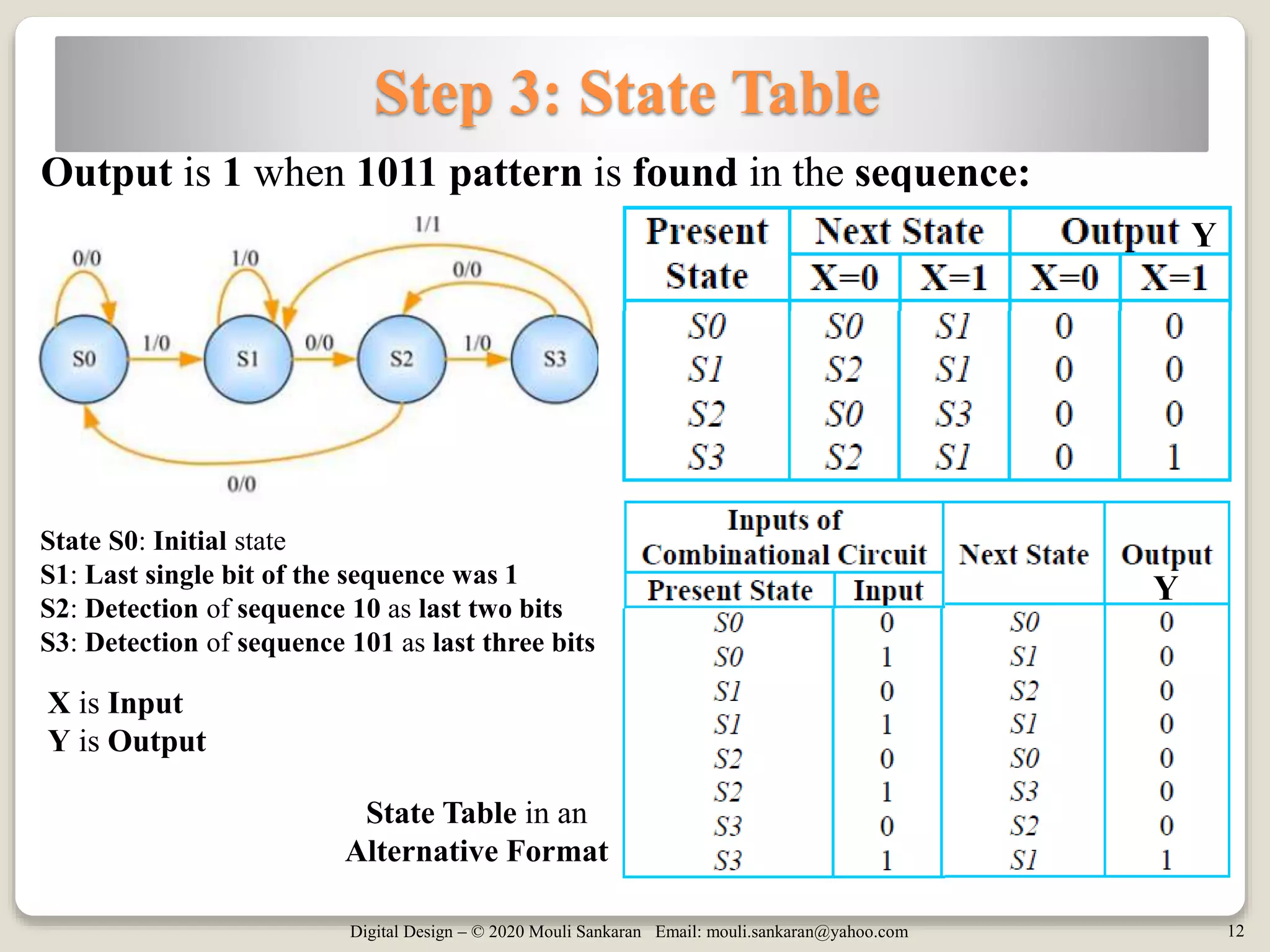
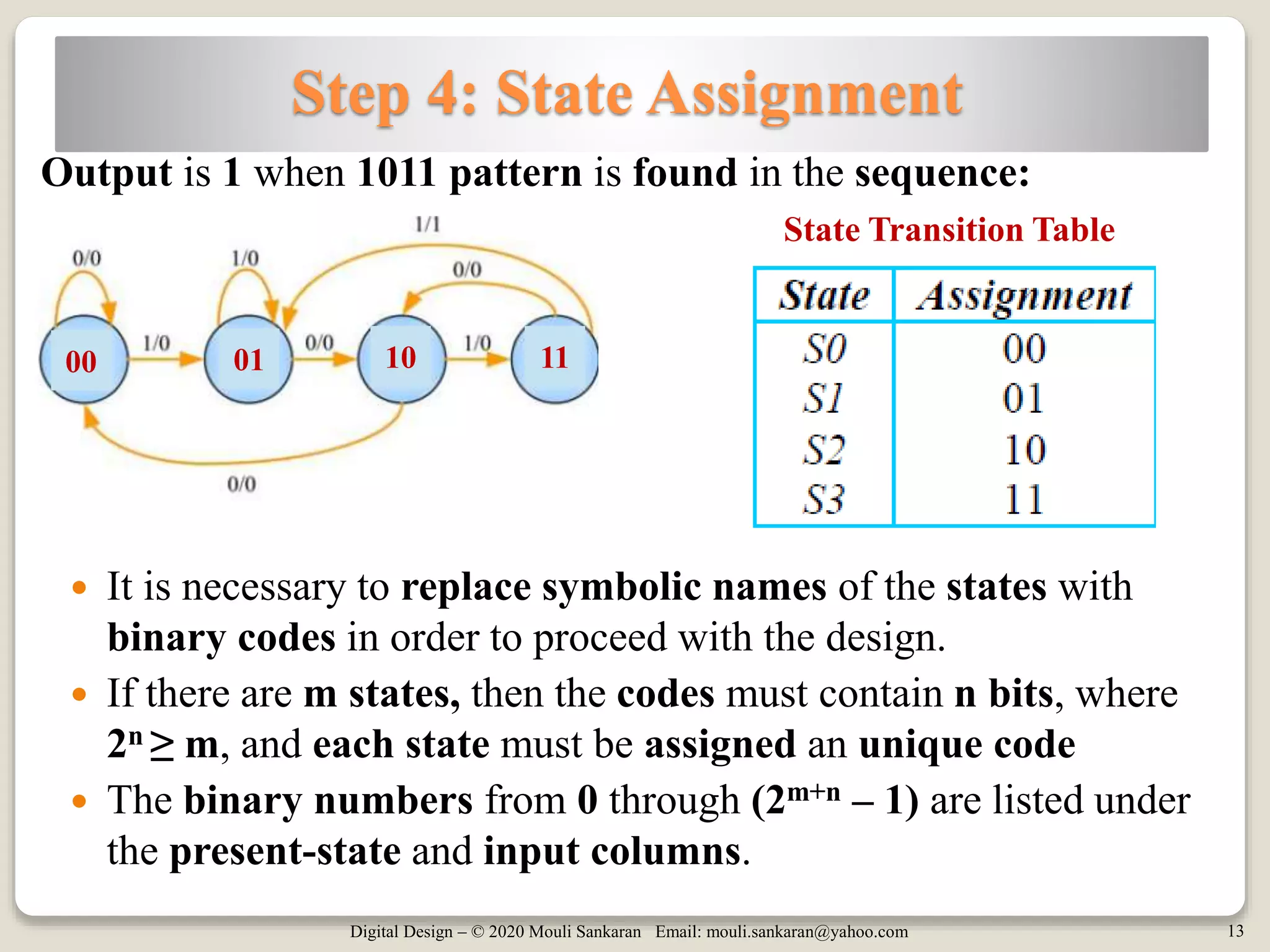


The document provides an overview of the design of sequential circuits, including state diagrams, design steps, and a specific example of a sequence recognizer for the input sequence 1011. It outlines the steps involved in designing such circuits, starting from problem definition to developing state tables and state assignments. Additionally, it includes examples demonstrating how to recognize specific patterns in sequences.